ters, including [E1.00] = 35 (X1 set to 'Enable'), [E1.01] = 34 (X2 set to 'Re‐
set'), will be pre-set automatically in ASF.
The digital inputs F2.16…F2.20, are mutually exclusive, which therefore do
not allow for any identical setting between the parameters, otherwise warning
APF1 will be triggered.
The sensors for oil filter, oil level and oil temperature will be connected to the
frequency converter EFC 5610. Therefore, ASF have to detect IO1 card and
work with it. The error and warnings will be indicated by the LED and in the
status word. If an error occurs, the drive needs to be stopped.
''Oil filter 1 / 2 pre-warning / warning 100%'' for oil filter warning sensor.
These signals will be automatically delayed by F4.76, that means a true sig‐
nal lasted longer than [F4.76] seconds will be acknowledged.
The default setting of terminal X1...X5, EX1...EX4 in ASF is ''0''. This means
no function from ASF is assigned, only EFC firmware functions assigned are
active.
Part of the EFC firmware parameters, including [E1.01] = 34 (X2 set to ''Re‐
set''), will be pre-set automatically in ASF.
The digital inputs F2.16…F2.24, are mutually exclusive, which therefore do
not allow for any identical setting (except 0) between the parameters, other‐
wise warning APF1 will be triggered.
Four pressure command parameters are available in ASF, and these can be
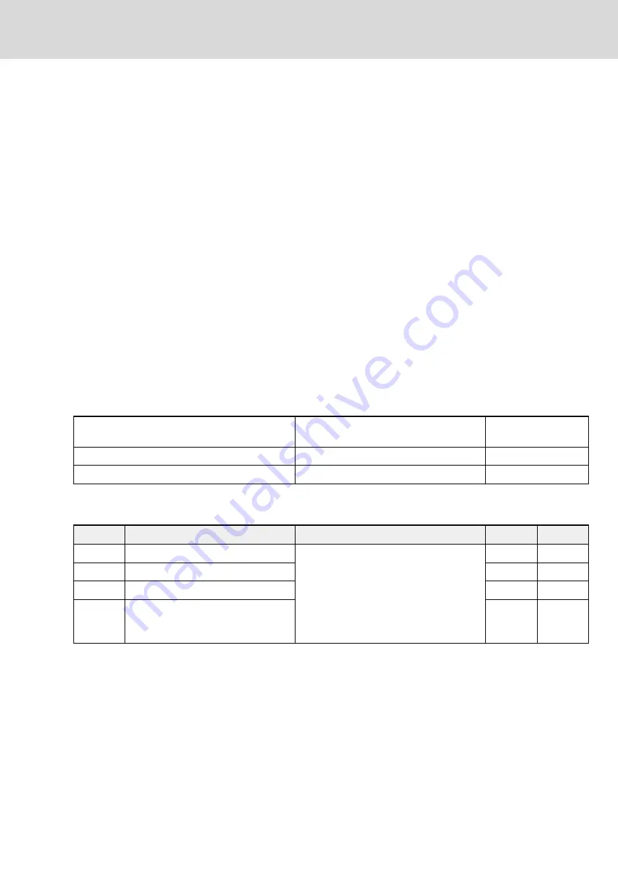
switched according to setting of F1.02 and DI or F1.04. The following table
shows the correspondence between pressure command values and the set‐
ting of the digital inputs.
Pressure command selection bit0 in digital inputs
X1...X5, EX1...EX4
0
1
Pressure command selection F1.04
0
1
Active pressure command from parameter
F1.05
F1.06
Tab. 7-23:
Pressure command selection with digital inputs
Digital and Relay Output
Code
Name
Setting Range
Default
Attri.
F2.36
DO1 output
0: No function assigned from ASF
1: Converter warning
2: Green flashing LED
3: Red flashing LED
4: Cooler on
5: Heater on
1
Run
F2.37
EDO output
0
Run
F2.40
Relay 1 output
0
Run
F2.41
Extension relay output
0
Run
Tab. 7-24:
Parameter list of digital and relay output
The default setting of DO1 when connected to ASF is '1', i.e. the frequency
converter warning. Meanwhile the default setting of relay when connected to
ASF is '0', this means when ASF is not active, the function of relay setting in
EFC firmware is active.
The parameter of EFC firmware, i.e. [E2.15] = 14 (set in the relay as frequen‐
cy converter error), has been set automatically through ASF.
DOK-SYTROX-DRN5020****-IT05-EN-P
Bosch Rexroth AG
101/143
Frequency-Controlled Pump Drive System Sytronix DRn 5020
Commissioning of Sytronix DRn 5020 System


