Cable extension
Power cables can be extended if required. The
following restrictions apply to any extension to the
power cable:
• Cable must be of a suitable gauge for the circuit
load.
• Each unit should have its own dedicated power
cable wired back to the distribution panel.
Total length
(max)
Supply voltage
Cable gauge
(AWG)
12 V
18
0–5 m (0–16.4 ft)
24 V
20
12 V
14
5–10 m
(16.4–32.8 ft)
24 V
18
12 V
12
10–15 m
(32.8–49.2 ft)
24 V
16
12 V
12
15–20 m
(49.2–65.5 ft)
24 V
14
Note:
a6x and a7x MFDs are 12 V only products. NEVER
connect a 12 V only product to a 24 V system.
Sharing a breaker
Where more than 1 piece of equipment shares a
breaker you must provide protection for the individual
circuits. E.g. by connecting an in-line fuse for each
power circuit.
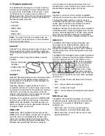
D11637-2
2
4
4
1
3
+
-
1
Positive (+) bar
2
Negative (-) bar
3
Circuit breaker
4
Fuse
Where possible, connect individual items of
equipment to individual circuit breakers. Where this
is not possible, use individual in-line fuses to provide
the necessary protection.
4.5 Power and data connection
The details below apply to MFDs which have a
combined power and data cable.
D12250-2
2
1
4
5
7
3
8
6
9
1.
Power and data connection
2.
Power and data cable
3.
Connection to vessel’s 12 V / 24 V dc power
supply
4.
Red cable (positive)
5.
Fuse
6.
Black cable (negative)
7.
Video input cable
8.
NMEA 0183 data cables
9.
Shield (drain) wire (thin black wire; must be
connected to RF ground point)
Power distribution
Raymarine recommends that all power connections
are made via a distribution panel.
• All equipment must be powered from a breaker or
switch, with appropriate circuit protection.
• All equipment should be wired to individual
breakers if possible.
Warning: Product grounding
Before applying power to this product,
ensure it has been correctly grounded, in
accordance with the instructions provided.
Grounding — Dedicated drain wire
The power cable supplied with this product includes
a dedicated shield (drain) wire for connection to a
vessel's RF ground point.
It is important that an effective RF ground is
connected to the system. A single ground point
should be used for all equipment. The unit can be
grounded by connecting the shield (drain) wire of
the power cable to the vessel's RF ground point.
On vessels without an RF ground system the shield
(drain) wire should be connected directly to the
negative battery terminal.
The dc power system should be either:
• Negative grounded, with the negative battery
terminal connected to the vessel's ground.
54
a Series / c Series / e Series
Содержание c125
Страница 2: ......
Страница 14: ...14 a Series c Series e Series ...
Страница 41: ...13 GPS receiver 14 Thermal camera 15 Wireless connection Planning the installation 41 ...
Страница 48: ...48 a Series c Series e Series ...
Страница 80: ...80 a Series c Series e Series ...
Страница 118: ...118 a Series c Series e Series ...
Страница 184: ...184 a Series c Series e Series ...
Страница 185: ...Chapter 13 Man Overboard MOB Chapter contents 13 1 Man overboard on page 186 Man Overboard MOB 185 ...
Страница 188: ...188 a Series c Series e Series ...
Страница 191: ...Chapter 15 Fuel manager Chapter contents 15 1 Fuel manager overview on page 192 Fuel manager 191 ...
Страница 206: ...206 a Series c Series e Series ...
Страница 228: ...228 a Series c Series e Series ...
Страница 290: ...290 a Series c Series e Series ...
Страница 310: ...310 a Series c Series e Series ...
Страница 340: ...340 a Series c Series e Series ...
Страница 374: ...374 a Series c Series e Series ...
Страница 422: ...422 a Series c Series e Series ...
Страница 436: ...436 a Series c Series e Series ...
Страница 462: ...462 a Series c Series e Series ...
Страница 463: ......
Страница 464: ...www raymarine com ...

