Appendix E Switch panel application
Vessel control and monitoring systems
When integrated with a vessel control and monitoring
system your multifunction display can provide
monitoring and controls for your power circuits,
breakers, switches and equipment.
The Switch Panel application can be used to:
• Show the status of power circuits, breakers,
switches and other equipment.
• Apply power to each circuit individually.
• Reset tripped breakers.
• Control power to individual equipment.
• Alert users to a tripped circuit.
Vessel control and monitoring system
connection
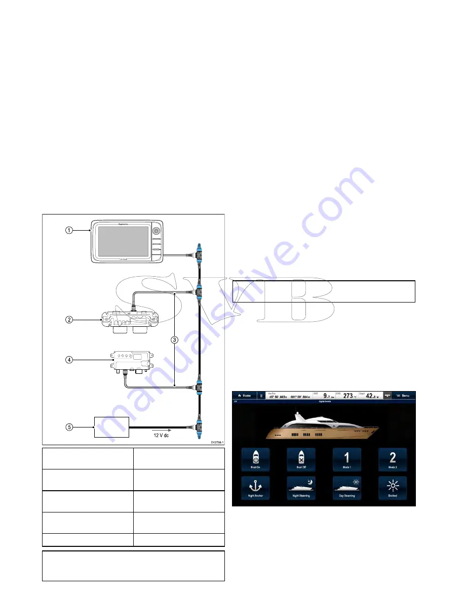
The multifunction display can connect to and control
an EmpirBus NXT vessel control and monitoring
system.
D12738-1
1
2 V dc
1
2
4
3
5
1
Raymarine multifunction
display.
2
EmpirBus NXT DCM (dc
module).
3
SeaTalk
ng
to DeviceNet
adaptor cable.
4
EmpirBus NXT MCU (Master
control unit).
5
12 V dc supply into backbone.
Note:
Ensure your vessel control and monitoring
system has been installed in accordance with the
instructions provided with the system.
Switch panel configuration
The switch panel application must be configured.
A Configuration file can be obtained from the system
supplier.
Loading a configuration file
The switch panel application will only be available
when a valid configuration file has been loaded.
1. Obtain the configuration file from the system
supplier.
2. Save the configuration file to the root directory of
your memory card.
3. Insert the memory card into the card reader on
your multifunction display.
4. From the homescreen select
Set-up
.
5. Select
System Settings
.
6. Select
External Devices
.
7. Select
Switch Panel Set-up
.
8. Select
Install Config File
.
9. If prompted select the memory card slot that
contains your configuration file.
The file browser is opened.
10. Select the configuration file.
11. Select
OK
.
You can now add the Switch panel application from
the Customize menu on the homescreen.
Note:
If your multifunction display only has 1 card
slot then step 9 is skipped.
Switch panel overview
The switch panel application is used to monitor and
control compatible vessel control and monitoring
systems. The pages and page layouts and vessel
schematics are configured at installation and are
unique for each vessel. The images below are
examples.
Example 1 — Switch panel mode page
If configured a Mode page provides controls to
switch between pre-configured modes.
In the example above selecting a mode icon will
place the system into the selected mode.
You can cycle through available pages to monitor or
control switches and configured groups of switches.
Example 2 — Vessel controls page
454
a Series / c Series / e Series
Содержание c125
Страница 2: ......
Страница 14: ...14 a Series c Series e Series ...
Страница 41: ...13 GPS receiver 14 Thermal camera 15 Wireless connection Planning the installation 41 ...
Страница 48: ...48 a Series c Series e Series ...
Страница 80: ...80 a Series c Series e Series ...
Страница 118: ...118 a Series c Series e Series ...
Страница 184: ...184 a Series c Series e Series ...
Страница 185: ...Chapter 13 Man Overboard MOB Chapter contents 13 1 Man overboard on page 186 Man Overboard MOB 185 ...
Страница 188: ...188 a Series c Series e Series ...
Страница 191: ...Chapter 15 Fuel manager Chapter contents 15 1 Fuel manager overview on page 192 Fuel manager 191 ...
Страница 206: ...206 a Series c Series e Series ...
Страница 228: ...228 a Series c Series e Series ...
Страница 290: ...290 a Series c Series e Series ...
Страница 310: ...310 a Series c Series e Series ...
Страница 340: ...340 a Series c Series e Series ...
Страница 374: ...374 a Series c Series e Series ...
Страница 422: ...422 a Series c Series e Series ...
Страница 436: ...436 a Series c Series e Series ...
Страница 462: ...462 a Series c Series e Series ...
Страница 463: ......
Страница 464: ...www raymarine com ...


