


Pronar RC2100-2
SECTION 3
3.14
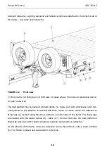
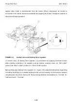
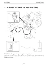
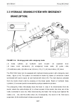
Design of the control system for the hydraulic support is shown in figure (3.11). The hydraulic
system is equipped with a support with a single acting cylinder. The support foot return is
accomplished by the tensioning springs located inside the support body. Supply conduit is
marked with information decal (5). The supply of hydraulic oil to the support is possible only
when cut-off valve (2) is set to „O” position (open). When towing the trailer, the support must
be folded to transport position and secured with a cotter pin. The cut-off valve must be set to
„Z” position (closed).
3.4
HYDRAULIC SYSTEM OF THE RAMPS (OPTION)
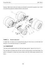
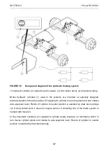
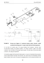
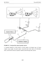
Design of the hydraulic system for folding and unfolding the ramps is shown in figure (3.12)
and on concept diagram – figure (3.13).
The ramps are controlled (raised / lowered) by means of double-acting cylinders, through a
single-section hydraulic distributor (1) located in the rear part of the frame, on the right side of
the trailer. The system is supplied from the external hydraulic system of the tractor. To
ensure correct connection, the supply conduit and the return conduit are marked with
information decals (7) and (8).
Hydraulic distributor (9) - (option) has a floating section that enforces free movement of
hydraulic cylinder pistons in order to facilitate operation.
Working positions of hydraulic distributor
(0) Neutral position,
(1) Rising the ramps - spring loaded lever automatically returns to its vertical position,
(2) Lowering the ramps - spring loaded lever automatically returns to its vertical position,
(3) Floating position – lever on latch (option).
DANGER
Before lowering or rising the ramps, make certain that there are no bystanders or other
obstacles in the ramp lowering or rising zone.
Be especially careful when lowering or raising the ramps because the ramps are heavy
and there is a risk of crushing.
Содержание RC2100-2
Страница 2: ......
Страница 6: ......
Страница 10: ...5 11 TROUBLESHOOTING 5 31 ...
Страница 11: ...SECTION 1 BASIC INFORMATION ...
Страница 24: ...PRONAR RC2100 2 SECTION 1 1 14 ...
Страница 25: ...SECTION 2 SAFETY ADVICE ...
Страница 40: ...Pronar RC2100 2 SECTION 2 2 16 FIGURE 2 3 Locations of information and warning decals ...
Страница 41: ...SECTION 3 DESIGN AND OPERATION ...
Страница 59: ...SECTION 4 CORRECT USE ...
Страница 78: ...Pronar RC2100 2 SECTION 4 4 20 ...
Страница 79: ...SECTION 5 MAINTENANCE ...
Страница 110: ...Pronar RC2100 2 SECTION 5 5 32 FIGURE 5 12 Lubrication points part 1 ...
Страница 111: ...SECTION 5 Pronar RC2100 2 5 33 FIGURE 5 13 Lubrication points part 2 ...
Страница 119: ...NOTES ...
Страница 120: ... ...
Страница 121: ...ANNEX A Tyre dimensions LP TYRES WHEEL RIM 1 215 75 R17 5 135 133 J 17 5x6 75 ...


