


SECTION 3
Pronar RC2100-2
3.9
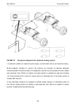
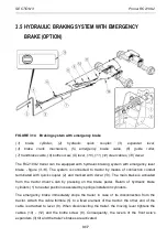
FIGURE 3.7
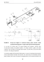
Design and diagram of combined braking system (double conduit
pneumatic braking single conduit hydraulic braking system)
(1) air tank, (2) control valve, (3) manual braking force regulator, (4) relay valve,
(5) pneumatic cylinder, (6) hydraulic cylinder, (7) conduit connector, yellow, (8) conduit
connector, red, (9) air filter, (10) hydraulic quick coupler, (11) drain valve, (12) air tank control
connector, (13) spring, (H) hydraulics
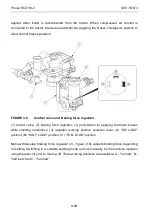
In the trailer equipped with pneumatic brake system, in case of an inadvertent disconnection
of the conduit between the trailer and the tractor, the control valve will automatically activate
trailer's brakes. Valve used in the system is equipped with a circuit causing the brakes to be
Содержание RC2100-2
Страница 2: ......
Страница 6: ......
Страница 10: ...5 11 TROUBLESHOOTING 5 31 ...
Страница 11: ...SECTION 1 BASIC INFORMATION ...
Страница 24: ...PRONAR RC2100 2 SECTION 1 1 14 ...
Страница 25: ...SECTION 2 SAFETY ADVICE ...
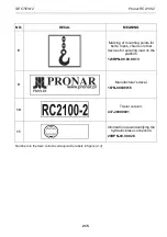
Страница 40: ...Pronar RC2100 2 SECTION 2 2 16 FIGURE 2 3 Locations of information and warning decals ...
Страница 41: ...SECTION 3 DESIGN AND OPERATION ...
Страница 59: ...SECTION 4 CORRECT USE ...
Страница 78: ...Pronar RC2100 2 SECTION 4 4 20 ...
Страница 79: ...SECTION 5 MAINTENANCE ...
Страница 110: ...Pronar RC2100 2 SECTION 5 5 32 FIGURE 5 12 Lubrication points part 1 ...
Страница 111: ...SECTION 5 Pronar RC2100 2 5 33 FIGURE 5 13 Lubrication points part 2 ...
Страница 119: ...NOTES ...
Страница 120: ... ...
Страница 121: ...ANNEX A Tyre dimensions LP TYRES WHEEL RIM 1 215 75 R17 5 135 133 J 17 5x6 75 ...


