


SECTION 3
Pronar RC2100-2
3.7
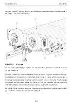
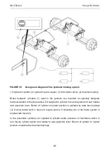
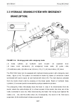
FIGURE 3.5
Design and diagram of the hydraulic braking system
(1) hydraulic cylinder, (2) hydraulic quick coupler, (3) information decal, (4) draw back spring
Brake hydraulic cylinders (1) used in the systems are mounted on specially designed
brackets welded to the wheel axles. Oil supplied to cylinder moves the piston rod and rotates
axle expander lever. Return of cylinder to neutral position is assisted by draw back springs
(4). During normal work it does not require service. Connecting line of the brake system is
marked with decal (3).
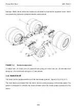
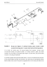
In the pneumatic cylinders, air supplied to cylinder exerts pressure on membrane which in
turn moves cylinder piston and rotates to axle expander lever. Return of cylinder to neutral
position is assisted by draw back springs.
Содержание RC2100-2
Страница 2: ......
Страница 6: ......
Страница 10: ...5 11 TROUBLESHOOTING 5 31 ...
Страница 11: ...SECTION 1 BASIC INFORMATION ...
Страница 24: ...PRONAR RC2100 2 SECTION 1 1 14 ...
Страница 25: ...SECTION 2 SAFETY ADVICE ...
Страница 40: ...Pronar RC2100 2 SECTION 2 2 16 FIGURE 2 3 Locations of information and warning decals ...
Страница 41: ...SECTION 3 DESIGN AND OPERATION ...
Страница 59: ...SECTION 4 CORRECT USE ...
Страница 78: ...Pronar RC2100 2 SECTION 4 4 20 ...
Страница 79: ...SECTION 5 MAINTENANCE ...
Страница 110: ...Pronar RC2100 2 SECTION 5 5 32 FIGURE 5 12 Lubrication points part 1 ...
Страница 111: ...SECTION 5 Pronar RC2100 2 5 33 FIGURE 5 13 Lubrication points part 2 ...
Страница 119: ...NOTES ...
Страница 120: ... ...
Страница 121: ...ANNEX A Tyre dimensions LP TYRES WHEEL RIM 1 215 75 R17 5 135 133 J 17 5x6 75 ...


