S
ETTING
I
NTERNAL
F
UNCTIONS
W
ELDING
C
ONDITION
C
HAPTER
6
82
)$XWR6HPLDXWRPRGH
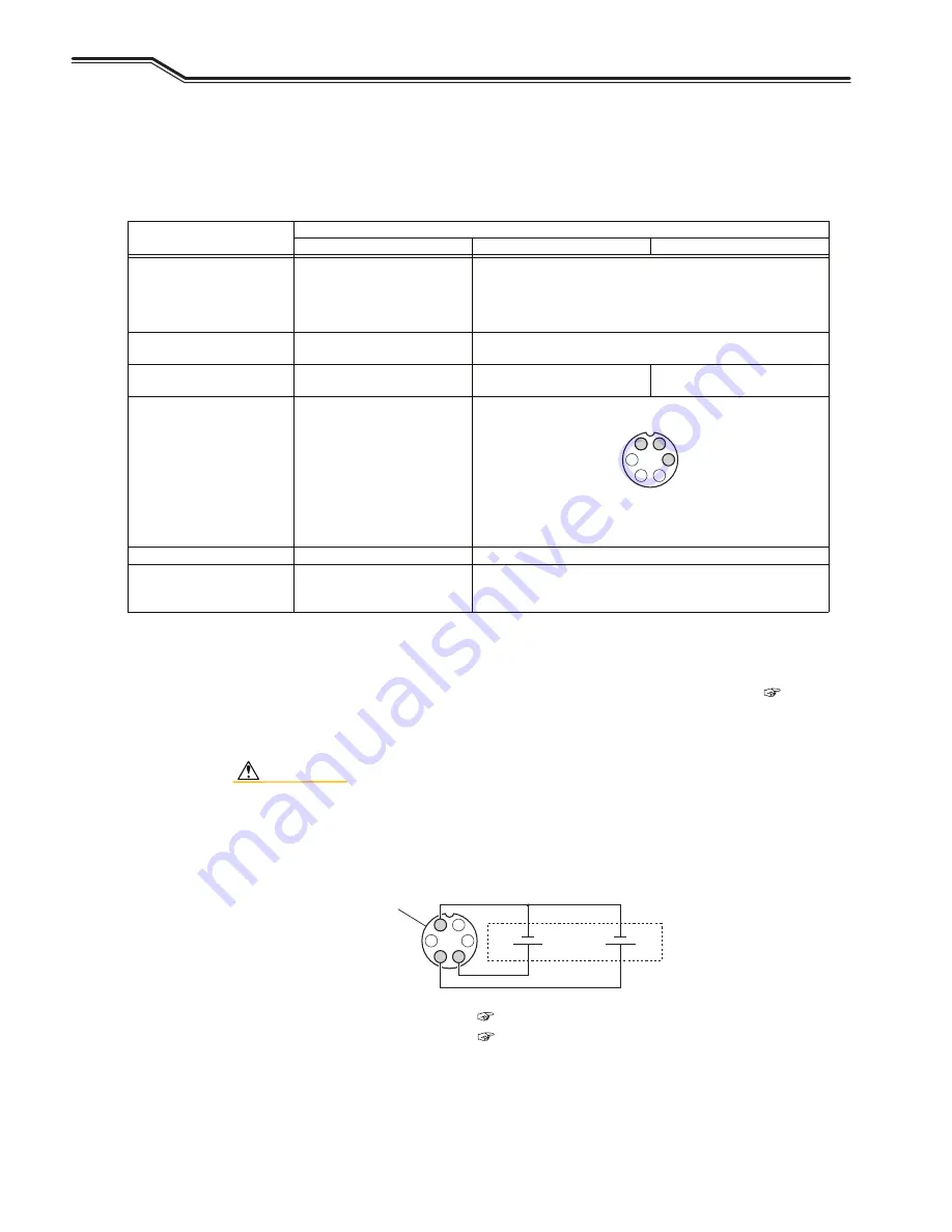
In combining the welding power source with a robot or an automatic machine, set I/O (interface) of the welding source
according to the application.
For the settings "0" to "2", refer to the table below. The settings "3" and "4" are the modes specifically for the use with OTC
robots. For details, refer to the instruction manual of the robot controller.
Parameter
Setting
0 (Semi-automatic)
1 (Automatic machine 1)
2 (Automatic machine 2)
Cancellation of operation stop
After short-circuiting the pins [3]-
[4] operation stop terminals on the
external connection terminal block
TM3, and turn the power on again.
(*4)
Short-circuit the operation stop terminal pins [3]-[4] on the external
connection terminal block TM3. (*4)
Stuck wire removal voltage (*1) Voltage is not output.
Voltage is output for approx. 0.2 seconds after completion of anti-stick
process.
Welding current/voltage setting
Set by operation panel or remote
control.
Set by external command
voltage(*2)
Set by operation panel or remote
control.
Inching
Operation by operation panel or
remote control.
Set on the operation panel or short-circuit the pins [1]-[5]-[6] of the
analog remote control receptacle (CON2).
<Analog remote control receptacle> (*5)
The above figure shows the front view of analog remote control
receptacle which is allocated on the front of welding power source.
Retract function (*3)
Disabled
Enabled
Error reset
After removing the cause of error,
the power is restored.
After removing the cause of error, the power is restored.
Or open/short-circuit the deactivated terminal pins [3]-[4] of the
external connection terminal block TM3. (*4)
*1: In the "Auto" mode, voltage to release welding is output for approx. 0.2 seconds after the anti-stick process. This voltage is
output even if the wire is not welded.
*2: If an external command voltage is input, it should be input to the terminal pins ([1]-[3], [1]-[4]) of the remote control receptacle
as shown in the below figure.
Relationship between input and output is as the charts provided in "F5: Maximum external command voltage
-
". (
6.7.2.4
-
F5: Maximum external command voltage)
Ensure that the command voltage is input at least 100 ms before the start signal is input.
Use the external power source with current capacity of 0.5 mA or more.
CAUTION
• Supply 0V to 15 V to E1 and E2.
Exceeding 15 V may result in damage to the control circuit of the welding power source.
*3: In the "Auto" mode, "3" (Retract) can be allocated to the functions of external input terminals of F29 - F32.
For more information on the retract function, refer to (
6.7.2.22
-
F29 to F32: External input terminal setting)
*4: For the details of external connection terminal block; (
4.5.2
-
Connection of automatic machine
-
)
*5: For the applicable plug of analog remote control receptacles: See specification DPC25-6A-1H-Z/Part No. 4730-009.
1
2
3
4
5
6
2
5
6
E2
(Welding current)
E1
(Welding current)
External power source
0 to 15 V,
0.5 mA or more capacity
1
3
4
Analog remote control
+
+
receptacle (*5)
Содержание Welbee M350 II
Страница 1: ...Welbee M350 II M500 II OWNER S MANUAL July 2021 Manual No P30355 1 DAIHEN Corporation...
Страница 139: ...137 Chapter 10 Reference Materials REFERENCE DRAWING REFERENCE MATERIALS CHAPTER 10 6FKHPDWLF GLDJUDP WB M352...
Страница 140: ...REFERENCE DRAWING REFERENCE MATERIALS CHAPTER 10 138...
Страница 141: ...139 Chapter 10 Reference Materials REFERENCE DRAWING REFERENCE MATERIALS CHAPTER 10 WB M502...
Страница 142: ...REFERENCE DRAWING REFERENCE MATERIALS CHAPTER 10 140...


