


10-19
Para
me-
ter
No.
Reg-
ister
No.
Name
Description
Set-
ting
range
Unit
of
set-
ting
Defaul
t set-
ting
Chan-
ges dur-
ing
opera-
tion
Ref-
er-
ence
page
n089
0159
DC injec-
tion brak-
ing current
Used to impose DC on the induction motor for
braking control.
Set the DC braking current in percentage
0 to
100
1%
50
No
6-29
n090
015A DC injec-
tion brak-
ing-to-stop
time
Set the DC braking current in percentage
based on the rated current of the Inverter as
100%.
Output
frequency
0.0 to
25.5
0.1 s
0.5
No
6-29
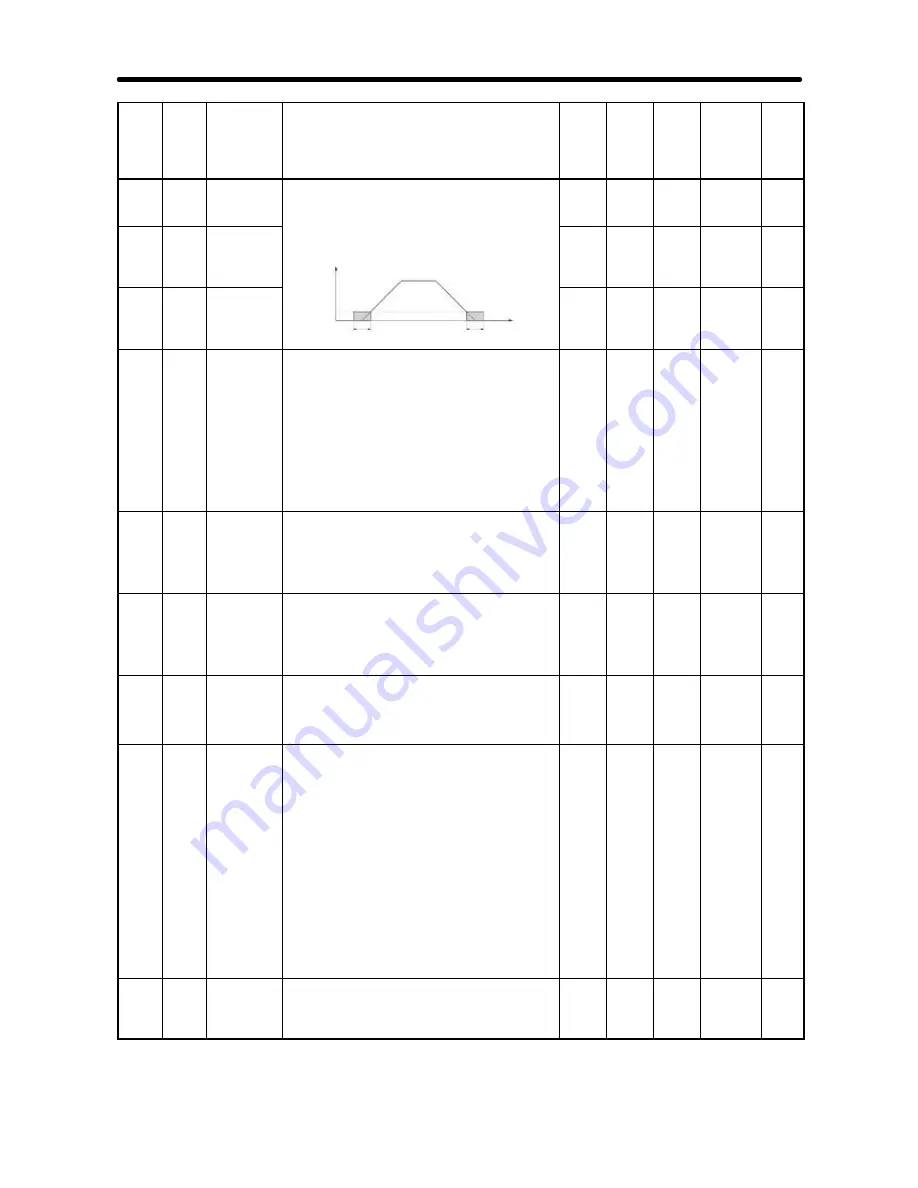
n091
015B Startup DC
injection
braking
time
frequency
Time
Minimum
output
frequency
(n016)
n091
n090
0.0 to
25.5
0.1 s
0.0
No
6-29
n092
015C Stall pre-
vention
during
decelera-
tion
Used to select a function to change the
deceleration time of the motor automatically so
that there will be no overvoltage imposed on
the motor during deceleration.
0: Stall prevention during deceleration enabled
1: Stall prevention during deceleration disabled
Note
Be sure to set the parameter to 1 when
the Braking Resistor Unit or a braking
resistor is used as an option.
0, 1
1
0
No
6-31
n093
015D Stall pre-
vention
level dur-
ing accel-
eration
Used to select a function to stop the
acceleration of the motor automatically for stall
prevention during acceleration.
Set the level in percentage based on the rated
current of the Inverter as 100%.
30 to
200
1%
170
No
6-32
n094
015E Stall pre-
vention
level dur-
ing opera-
tion
Used to select a function to reduce the output
frequency of the Inverter automatically for stall
prevention during operation.
Set the level in percentage based on the rated
current of the Inverter as 100%.
30 to
200
1%
160
No
6-32
n095
015F Frequency
detection
level
Used to set the frequency to be detected.
Note
The parameter n57, n58 and n59 for mul-
ti-function output must be set for the out-
put of frequency detection levels 1 and 2.
0.00
to
400.0
0.01
Hz
0.00
No
6-47
n096
0160
Overtorque
detection
function
selection 1
Used to enable or disable overtorque detection
and select the processing method after
overtorque detection.
0: Overtorque detection disabled
1: Overtorque detection only when speed
coincides and operation continues (issues
alarm)
2: Overtorque detection only when speed
coincides and output turned OFF (for
protection)
3: Overtorque always detected and operation
continues (issues alarm)
4: Overtorque always detected and output
turned OFF (for protection)
0 to 4 1
0
No
6-35
n097
0161
Overtorque
detection
function
selection 2
Select the item to detect overtorque.
0: Detected from output torque.
1: Detected from output current.
0, 1
1
0
No
6-36
List of Parameters
Chapter 10
Содержание SYSDRIVE 3G3MV A2002
Страница 1: ...USER S MANUAL SYSDRIVE 3G3MV Multi function Compact Inverter Cat No I527 E2 02...
Страница 15: ...Chapter 1 Overview 1 1 Function 1 2 Nomenclature 1 3 New Features 1...
Страница 24: ...Chapter 2 Design 2 1 Installation 2 2 Wiring 2...
Страница 69: ...Chapter 3 Preparing for Operation and Monitoring 3 1 Nomenclature 3 2 Parameter Copy and Verify Function 3...
Страница 89: ...Chapter 4 Test Run 4 1 Procedure for Test Run 4 2 Operation Example 4...
Страница 286: ...Chapter 9 Specifications 9 1 Inverter Specifications 9 2 Option Specifications 9...
Страница 296: ...9 11 D 3G3MV PFI1040 E Three 5 dia holes Four M4 holes for Inverter mounting use Specifications Chapter 9...
Страница 298: ...9 13 D 3G3MV PFI2030 E Four M4 holes for Inverter mounting use Three 5 dia holes Specifications Chapter 9...
Страница 299: ...9 14 D 3G3MV PFI2050 E Four M5 holes for Inverter mounting use Three 6 dia holes Specifications Chapter 9...
Страница 301: ...9 16 D 3G3MV PRS3030V Four M5 holes for Inverter mounting use Three 6 dia holes Specifications Chapter 9...
Страница 311: ...Chapter 10 List of Parameters 10...
Страница 342: ...Chapter 11 Using the Inverter for a Motor 11...
Страница 348: ...Appendix A Standard Models...


