


Universal Serial Bus Interface
MCF5253 Reference Manual, Rev. 1
24-132
Freescale Semiconductor
NOTE
Before resume signaling can be used, the host must enable it by using the
Set Feature command defined in USB 2.0 Specification, Chapter 9,
Device
Framework
.
24.11.3 Managing Endpoints
The USB 2.0 specification defines an endpoint, also called a device endpoint or an address endpoint as a
uniquely addressable portion of a USB device that can source or sink data in a communications channel
between the host and the device. The endpoint address is specified by the combination of the endpoint
number and the endpoint direction.
The channel between the host and an endpoint at a specific device represents a data pipe. Endpoint 0 for a
device is always a control type data channel used for device discovery and enumeration. Other types of
endpoints support by USB include bulk, interrupt, and isochronous. Each endpoint type has specific
behavior related to packet response and error handling. More detail on endpoint operation can be found in
the USB 2.0 specification.
The USB_DR supports up to six(6) endpoint specified numbers. The DCD can enable, disable and
configure each endpoint.
Each endpoint direction is essentially independent and can be configured with differing behavior in each
direction. For example, the DCD can configure endpoint 1-IN to be a bulk endpoint and endpoint 1-OUT
to be an isochronous endpoint. This helps to conserve the total number of endpoints required for device
operation. The only exception is that control endpoints must use both directions on a single endpoint
number to function as a control endpoint. Endpoint 0 is, for example, is always a control endpoint and uses
the pair of directions.
Each endpoint direction requires a queue head allocated in memory. If the maximum of 6 endpoint
numbers, one for each endpoint direction are being used by the device controller, then 12 queue heads are
required. The operation of an endpoint and use of queue heads are described later in this document.
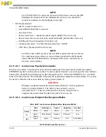
24.11.3.1 Endpoint Initialization
After a hardware reset, all endpoints except endpoint zero are uninitialized and disabled. The DCD must
configure and enable each endpoint by writing to configuration bit in the ENDPTCTRL
n
register. Each
32-bit ENDPTCTRL
n
is split into an upper and lower half. The lower half of ENDPTCTRL
n
is used to
configure the receive or OUT endpoint and the upper half is likewise used to configure the corresponding
transmit or IN endpoint. Control endpoints must be configured the same in both the upper and lower half
of the ENDPTCTRL
n
register otherwise the behavior is undefined.
shows how to construct a
configuration word for endpoint initialization.
Table 24-81. Device Controller Endpoint Initialization
Field
Value
Data Toggle Reset
1
Data Toggle Inhibit
0
Содержание MCF5253
Страница 1: ...Document Number MCF5253RM Rev 1 08 2008 MCF5253 Reference Manual...
Страница 26: ...MCF5253 Reference Manual Rev 1 xxvi Freescale Semiconductor...
Страница 32: ...MCF5253 Reference Manual Rev 1 xxxii Freescale Semiconductor...
Страница 46: ...MCF5253 Introduction MCF5253 Reference Manual Rev 1 1 14 Freescale Semiconductor...
Страница 62: ...Signal Description MCF5253 Reference Manual Rev 1 2 16 Freescale Semiconductor...
Страница 98: ...Instruction Cache MCF5253 Reference Manual Rev 1 5 10 Freescale Semiconductor...
Страница 104: ...Static RAM SRAM MCF5253 Reference Manual Rev 1 6 6 Freescale Semiconductor...
Страница 128: ...Synchronous DRAM Controller Module MCF5253 Reference Manual Rev 1 7 24 Freescale Semiconductor...
Страница 144: ...Bus Operation MCF5253 Reference Manual Rev 1 8 16 Freescale Semiconductor...
Страница 176: ...System Integration Module SIM MCF5253 Reference Manual Rev 1 9 32 Freescale Semiconductor...
Страница 198: ...Analog to Digital Converter ADC MCF5253 Reference Manual Rev 1 12 6 Freescale Semiconductor...
Страница 246: ...DMA Controller MCF5253 Reference Manual Rev 1 14 18 Freescale Semiconductor...
Страница 282: ...UART Modules MCF5253 Reference Manual Rev 1 15 36 Freescale Semiconductor...
Страница 298: ...Queued Serial Peripheral Interface QSPI Module MCF5253 Reference Manual Rev 1 16 16 Freescale Semiconductor...
Страница 344: ...Audio Interface Module AIM MCF5253 Reference Manual Rev 1 17 46 Freescale Semiconductor...
Страница 362: ...I2 C Modules MCF5253 Reference Manual Rev 1 18 18 Freescale Semiconductor...
Страница 370: ...Boot ROM MCF5253 Reference Manual Rev 1 19 8 Freescale Semiconductor...


