


Universal Serial Bus Interface
MCF5253 Reference Manual, Rev. 1
Freescale Semiconductor
24-19
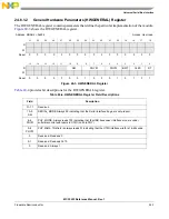
8
SLI
DCSuspend. This is a non-EHCI bit that is present on the USB OTG module only. When a device controller
enters a suspend state from an active state, this bit is set. The device controller clears the bit upon exiting from
a suspend state. Used only by the device controller.
1 Suspended.
0 Active.
7
SRI
Host mode:
This is a non-EHCI status bit. In host mode, this bit will be set every 125us, provided the PHY clock is present
and running (for example, the port is NOT suspended), and can be used by the host controller driver as a time
base.
Device mode:
SOF Received. When the controller detects a Start Of (micro) Frame, this bit will be set. When a SOF is
extremely late, the controller will automatically set this bit to indicate that an SOF was expected. Therefore, this
bit will be set roughly every 1 msec in device FS mode and every 125 msec in HS mode and will be
synchronized to the actual SOF that is received. Since the controller is initialized to FS before connect, this bit
will be set at an interval of 1 msec during the prelude to the connect and chirp.
The software writes a 1 to this bit to clear it.
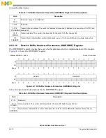
6
URI
USB Reset Received. This is a non-EHCI bit that is present on the USB OTG module only. When the controller
detects a USB Reset and enters the default state, this bit will be set. The software can write a 1 to this bit to
clear the USB Reset Received status bit. Used only in device mode.
1 Reset received.
0 No reset received.
5
AAI
Interrupt on Async Advance. The system software can force the controller to issue an interrupt the next time
the controller advances the asynchronous schedule by writing a one to the Interrupt on Async Advance Doorbell
bit in the USBCMD register. This status bit indicates the assertion of that interrupt source. Used only in host
mode.
1 Async advance interrupt.
0 No async advance interrupt.
4
SEI
System Error. This bit is set whenever an error is detected on the system bus. If the System Error Enable (SEE)
bit in the USBINTR is set, an interrupt will be generated. The interrupt and status bits will remain asserted until
cleared by writing a 1 to this bit. Additionally, when in host mode, the RUN/STOP (RS) bit of the USBCMD
register is cleared, effectively disabling the controller. For the controller in device mode, an interrupt is
generated, but no other action is taken.
1 Error.
0 Normal operation.
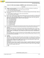
3
FRI
Frame List Rollover. The controller sets this bit to a one when the Frame List Index rolls over from its maximum
value to zero. The exact value at which the rollover occurs depends on the frame list size. For example. If the
frame list size (as programmed in the Frame List Size field of the USBCMD register) is 1024, the Frame Index
Register rolls over every time FRINDEX [1 3] toggles. Similarly, if the size is 512, the controller sets this bit to
a one every time FHINDEX [12] toggles. Used only in host mode.
2
PCI
Host mode:
Port Change Detect. The controller sets this bit to a one when on any port a Connect Status occurs, a Port
Enable/Disable Change occurs, an Over Current Change occurs, or the Force Port Resume bit is set as the
result of a J-K transition on the suspended port.
Device mode:
The controller sets this bit to a one when it enters the full or high-speed operational state. When the it exits the
full or high-speed operation states due to Reset or Suspend events, the notification mechanisms are the USB
Reset Received bit and the DCSuspend bits respectively.
This bit is not EHCI compatible.
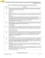
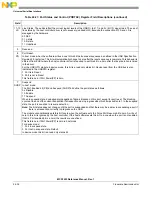
Table 24-16. USB Status Register (USBSTS) Register Field Descriptions (continued)
Field
Description
Содержание MCF5253
Страница 1: ...Document Number MCF5253RM Rev 1 08 2008 MCF5253 Reference Manual...
Страница 26: ...MCF5253 Reference Manual Rev 1 xxvi Freescale Semiconductor...
Страница 32: ...MCF5253 Reference Manual Rev 1 xxxii Freescale Semiconductor...
Страница 46: ...MCF5253 Introduction MCF5253 Reference Manual Rev 1 1 14 Freescale Semiconductor...
Страница 62: ...Signal Description MCF5253 Reference Manual Rev 1 2 16 Freescale Semiconductor...
Страница 98: ...Instruction Cache MCF5253 Reference Manual Rev 1 5 10 Freescale Semiconductor...
Страница 104: ...Static RAM SRAM MCF5253 Reference Manual Rev 1 6 6 Freescale Semiconductor...
Страница 128: ...Synchronous DRAM Controller Module MCF5253 Reference Manual Rev 1 7 24 Freescale Semiconductor...
Страница 144: ...Bus Operation MCF5253 Reference Manual Rev 1 8 16 Freescale Semiconductor...
Страница 176: ...System Integration Module SIM MCF5253 Reference Manual Rev 1 9 32 Freescale Semiconductor...
Страница 198: ...Analog to Digital Converter ADC MCF5253 Reference Manual Rev 1 12 6 Freescale Semiconductor...
Страница 246: ...DMA Controller MCF5253 Reference Manual Rev 1 14 18 Freescale Semiconductor...
Страница 282: ...UART Modules MCF5253 Reference Manual Rev 1 15 36 Freescale Semiconductor...
Страница 298: ...Queued Serial Peripheral Interface QSPI Module MCF5253 Reference Manual Rev 1 16 16 Freescale Semiconductor...
Страница 344: ...Audio Interface Module AIM MCF5253 Reference Manual Rev 1 17 46 Freescale Semiconductor...
Страница 362: ...I2 C Modules MCF5253 Reference Manual Rev 1 18 18 Freescale Semiconductor...
Страница 370: ...Boot ROM MCF5253 Reference Manual Rev 1 19 8 Freescale Semiconductor...


