


Universal Serial Bus Interface
MCF5253 Reference Manual, Rev. 1
24-28
Freescale Semiconductor
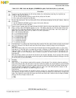
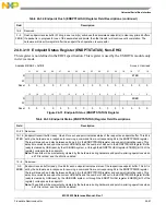
Address MBAR2 0x764
Access: User read/write
31
30
29
28
27
26
25
24
23
22
21
20
19
18
17
16
R
TXFIFOTHRES
W
Reset
0
0
0
0
0
0
0
0
0
0
0
0
0
0
0
0
15
14
13
12
11
10
9
8
7
6
5
4
3
2
1
0
R
TXSCHHEALTH
TXSCHOH
W
Reset
0
0
0
0
0
0
0
0
0
0
0
0
0
0
0
0
Figure 24-23. Transmit FIFO Tuning Controls (TXFILLTUNING) Register
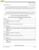
Table 24-25. Transmit FIFO Tuning Controls (TXFILLTUNING) Register Field Descriptions
Field
Description
31–22
Reserved.
21–16
TXFIFOTHRES
FIFO Burst Threshold. These bits control the number of data bursts that are posted to the TX latency FIFO in
host mode before the packet begins on to the bus. The minimum value is 2 and this value should be a low as
possible to maximize USB performance. A higher value can be used in systems with unpredictable latency
and/or insufficient bandwidth where the FIFO may underrun because the data transferred from the latency
FIFO to USB occurs before it can be replenished from system memory. This value is ignored if the Stream
Disable bit in USBMODE register is set. When the SDIS bit is set, the host controller behaves as if
TXFIFOTHRES is set to the maximum value.
15–13
Reserved.
12–8
TXSCHHEALTH
Scheduler Health Counter. These bits increment when the host controller fails to fill the TX latency FIFO to the
level programmed by TXFIFOTHRES before running out of time to send the packet before the next
Start-Of-Frame.
This health counter measures the number of times this occurs to provide feedback to selecting a proper
TXSCHOH. Writing to this register clears the counter and this counter stops counting after reaching the
maximum of 31.
7–0
TXSCHOH
Scheduler Overhead. These bits add an additional fixed offset to the schedule time estimator described above
as T
ff
. As an approximation, the value chosen for this register should limit the number of back-off events
captured in the TXSCHHEALTH to less than 10 per second in a highly utilized bus. Choosing a value that is
too high for this register is not desired as it can needlessly reduce USB utilization.
The time unit represented in this register is 1.267
μ
s when a device is connected in High-Speed Mode.
The time unit represented in this register is 6.333
μ
s when a device is connected in Low/Full-speed Mode.
For most applications, TXSCHOH can be set to 4 or less. A good value to begin with is: TXFIFOTHRES *
(BURSTSIZE * 4 bytes-per-word) / (40 * TimeUnit), always rounded to the next higher integer. TimeUnit is
either 1.267 or 6.333 as noted earlier in this description. For example, if TXFIFOTHRES is 5 and BURSTSIZE
is 8, then set TXSCHOH to 5*(8*4)/(40*1.267) = 4 for a high-speed link. If this value of TXSCHOH results in a
TXSCHHEALTH count of 0 per second, try lowering the value by 1 if optimizing performance is desired. If
TXSCHHEALTH exceeds 10 per second, try raising the value by 1.
If streaming mode is disabled via the USBMODE register, treat TXFIFOTHRES as the maximum value for
purposes of the TXSCHOH calculation.
Содержание MCF5253
Страница 1: ...Document Number MCF5253RM Rev 1 08 2008 MCF5253 Reference Manual...
Страница 26: ...MCF5253 Reference Manual Rev 1 xxvi Freescale Semiconductor...
Страница 32: ...MCF5253 Reference Manual Rev 1 xxxii Freescale Semiconductor...
Страница 46: ...MCF5253 Introduction MCF5253 Reference Manual Rev 1 1 14 Freescale Semiconductor...
Страница 62: ...Signal Description MCF5253 Reference Manual Rev 1 2 16 Freescale Semiconductor...
Страница 98: ...Instruction Cache MCF5253 Reference Manual Rev 1 5 10 Freescale Semiconductor...
Страница 104: ...Static RAM SRAM MCF5253 Reference Manual Rev 1 6 6 Freescale Semiconductor...
Страница 128: ...Synchronous DRAM Controller Module MCF5253 Reference Manual Rev 1 7 24 Freescale Semiconductor...
Страница 144: ...Bus Operation MCF5253 Reference Manual Rev 1 8 16 Freescale Semiconductor...
Страница 176: ...System Integration Module SIM MCF5253 Reference Manual Rev 1 9 32 Freescale Semiconductor...
Страница 198: ...Analog to Digital Converter ADC MCF5253 Reference Manual Rev 1 12 6 Freescale Semiconductor...
Страница 246: ...DMA Controller MCF5253 Reference Manual Rev 1 14 18 Freescale Semiconductor...
Страница 282: ...UART Modules MCF5253 Reference Manual Rev 1 15 36 Freescale Semiconductor...
Страница 298: ...Queued Serial Peripheral Interface QSPI Module MCF5253 Reference Manual Rev 1 16 16 Freescale Semiconductor...
Страница 344: ...Audio Interface Module AIM MCF5253 Reference Manual Rev 1 17 46 Freescale Semiconductor...
Страница 362: ...I2 C Modules MCF5253 Reference Manual Rev 1 18 18 Freescale Semiconductor...
Страница 370: ...Boot ROM MCF5253 Reference Manual Rev 1 19 8 Freescale Semiconductor...


