


Universal Serial Bus Interface
MCF5253 Reference Manual, Rev. 1
Freescale Semiconductor
24-17
5
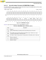
ASE
Asynchronous Schedule Enable. This bit controls whether the controller skips processing the Asynchronous
Schedule. Used only in host mode.
1 Use the ASYNCLISTADDR register to access the Asynchronous Schedule.
0 Do not process the Asynchronous Schedule.
4
PSE
Periodic Schedule Enable. This bit controls whether the controller skips processing the Periodic Schedule. Used only
in host mode.
1 Use the PERIODICLISTBASE register to access the Periodic Schedule.
0 Do not process the Periodic Schedule.
3–2
FS
Frame List Size. Together with bit 15 these bits make the FS[2:0] field. This field is Read/Write only if Programmable
Frame List Flag in the HCCPARAMS registers is set to 1. This field specifies the size of the frame list that controls
which bits in the Frame Index Register should be used for the Frame List Current index. Used only in host mode.
Note: Values below 256 elements are not defined in the EHCI specification.
000 1024 elements (4096 bytes)
001 512 elements (2048 bytes)
010 256 elements (1024 bytes)
011 128 elements (512 bytes)
100 64 elements (256 bytes)
101 32 elements (128 bytes)
110 16 elements (64 bytes)
111 8 elements (32 bytes)
1
RST
Controller Reset. The software uses this bit to reset the controller. This bit is cleared by the controller when the reset
process is complete. The software cannot terminate the reset process early by writing a zero to this register.
Host Mode:
When the software writes a one to this bit, the Host Controller resets its internal pipelines, timers, counters, state
machines etc. to their initial value. Any transaction currently in progress on USB is immediately terminated. A USB
reset is not driven on downstream ports. The software should not set this bit to a one when the HCHalted bit in the
USBSTS register is a zero. Attempting to reset an actively running host controller will result in undefined behavior.
Device Mode:
When the software writes a one to this bit, the controller resets its internal pipelines, timers, counters, state machines
etc. to their initial value. Any transaction currently in progress on USB is immediately terminated. Writing a one to this
bit in device mode is not recommended.
0
RS
Run/Stop.
Host Mode:
When set to a 1, the controller proceeds with the execution of the schedule. The controller continues execution as
long as this bit is set. When this bit is set to 0, the Host Controller completes the current transaction on the USB and
then halts. The HC Halted bit in the status register indicates when the Host Controller has finished the transaction
and has entered the stopped state. The software should not write a one to this field unless the controller is in the
Halted state (that is, HCHalted in the USBSTS register is a one).
Device Mode:
Writing a one to this bit will cause the controller to enable a pull-up on D+ and initiate an attach event. This control bit
is not directly connected to the pull-up enable, as the pull-up will become disabled upon transitioning into high-speed
mode. The software should use this bit to prevent an attach event before the controller has been properly initialized.
Writing a 0 to this will cause a detach event.
1 Run.
0 Stop.
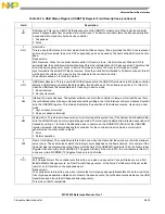
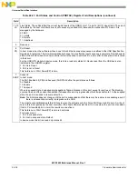
Table 24-15. USB Command Register (USBCMD) Register Field Descriptions (continued)
Field
Description
Содержание MCF5253
Страница 1: ...Document Number MCF5253RM Rev 1 08 2008 MCF5253 Reference Manual...
Страница 26: ...MCF5253 Reference Manual Rev 1 xxvi Freescale Semiconductor...
Страница 32: ...MCF5253 Reference Manual Rev 1 xxxii Freescale Semiconductor...
Страница 46: ...MCF5253 Introduction MCF5253 Reference Manual Rev 1 1 14 Freescale Semiconductor...
Страница 62: ...Signal Description MCF5253 Reference Manual Rev 1 2 16 Freescale Semiconductor...
Страница 98: ...Instruction Cache MCF5253 Reference Manual Rev 1 5 10 Freescale Semiconductor...
Страница 104: ...Static RAM SRAM MCF5253 Reference Manual Rev 1 6 6 Freescale Semiconductor...
Страница 128: ...Synchronous DRAM Controller Module MCF5253 Reference Manual Rev 1 7 24 Freescale Semiconductor...
Страница 144: ...Bus Operation MCF5253 Reference Manual Rev 1 8 16 Freescale Semiconductor...
Страница 176: ...System Integration Module SIM MCF5253 Reference Manual Rev 1 9 32 Freescale Semiconductor...
Страница 198: ...Analog to Digital Converter ADC MCF5253 Reference Manual Rev 1 12 6 Freescale Semiconductor...
Страница 246: ...DMA Controller MCF5253 Reference Manual Rev 1 14 18 Freescale Semiconductor...
Страница 282: ...UART Modules MCF5253 Reference Manual Rev 1 15 36 Freescale Semiconductor...
Страница 298: ...Queued Serial Peripheral Interface QSPI Module MCF5253 Reference Manual Rev 1 16 16 Freescale Semiconductor...
Страница 344: ...Audio Interface Module AIM MCF5253 Reference Manual Rev 1 17 46 Freescale Semiconductor...
Страница 362: ...I2 C Modules MCF5253 Reference Manual Rev 1 18 18 Freescale Semiconductor...
Страница 370: ...Boot ROM MCF5253 Reference Manual Rev 1 19 8 Freescale Semiconductor...


