


UART Modules
MCF5253 Reference Manual, Rev. 1
15-26
Freescale Semiconductor
15.4.11 Interrupt Mask Registers (UIMRn)
The UIMR registers select the corresponding bits in the UISR that cause an interrupt. By setting the bit,
the interrupt is enabled. If one of the bits in the UISR is set and the corresponding bit in the UIMR is also
set, the internal interrupt output is asserted. If the corresponding bit in the UIMR is zero, the state of the
bit in the UISR has no effect on the interrupt output. The UIMR does not mask the reading of the UISR.
Table 15-16. Interrupt Status Register (UISRn) Field Descriptions
Field
Description
7
COS
Change-of-State
1 A change-of-state has occurred at the CTS input and has been selected to cause an interrupt by programming bit
0 of the UACR.
0 COS bit in the UIPCR is not selected.
6–3
Reserved
2
DB
Delta Break
1 The receiver has detected the beginning or end of a received break.
0 No new break-change condition to report. Refer to
Section 15.4.5, “Command Registers (UCRn),”
for more
information on the reset break-change interrupt command.
1
RxRDY
Receiver Ready or FIFO Full
UMR1 bit 6 programs the function of this bit. It is a duplicate of either the FFULL or RxRDY bit of USR.
0
TxRDY
Transmitter Ready
This bit is the duplication of the TxRDY bit in USR.
1 The transmitter holding register is empty and ready to be loaded with a character.
0 The CPU loads the transmitter-holding register or the transmitter is disabled. Characters loaded into the
transmitter-holding register when TxRDY=0 are not transmitted.
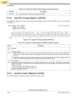
Address MBAR + $1D4 (UIMR0)
MBAR + $214 (UIMR1)
MBAR2 + $C14 (UIMR2)
Access: User write only
7
6
5
4
3
2
1
0
R
W
COS
DB
FFULL
TXRDY
Reset
0
0
0
0
0
0
0
0
Figure 15-18. Interrupt Mask Register (UIMRn)
Table 15-17. Interrupt Mask Register (UIMRn) Field Descriptions
Field
Description
7
COS
Change-of-State
1 Enable interrupt
0 Disable interrupt
6–3
Reserved
2
DB
Delta Break
1 Enable interrupt
0 Disable interrupt
Содержание MCF5253
Страница 1: ...Document Number MCF5253RM Rev 1 08 2008 MCF5253 Reference Manual...
Страница 26: ...MCF5253 Reference Manual Rev 1 xxvi Freescale Semiconductor...
Страница 32: ...MCF5253 Reference Manual Rev 1 xxxii Freescale Semiconductor...
Страница 46: ...MCF5253 Introduction MCF5253 Reference Manual Rev 1 1 14 Freescale Semiconductor...
Страница 62: ...Signal Description MCF5253 Reference Manual Rev 1 2 16 Freescale Semiconductor...
Страница 98: ...Instruction Cache MCF5253 Reference Manual Rev 1 5 10 Freescale Semiconductor...
Страница 104: ...Static RAM SRAM MCF5253 Reference Manual Rev 1 6 6 Freescale Semiconductor...
Страница 128: ...Synchronous DRAM Controller Module MCF5253 Reference Manual Rev 1 7 24 Freescale Semiconductor...
Страница 144: ...Bus Operation MCF5253 Reference Manual Rev 1 8 16 Freescale Semiconductor...
Страница 176: ...System Integration Module SIM MCF5253 Reference Manual Rev 1 9 32 Freescale Semiconductor...
Страница 198: ...Analog to Digital Converter ADC MCF5253 Reference Manual Rev 1 12 6 Freescale Semiconductor...
Страница 246: ...DMA Controller MCF5253 Reference Manual Rev 1 14 18 Freescale Semiconductor...
Страница 282: ...UART Modules MCF5253 Reference Manual Rev 1 15 36 Freescale Semiconductor...
Страница 298: ...Queued Serial Peripheral Interface QSPI Module MCF5253 Reference Manual Rev 1 16 16 Freescale Semiconductor...
Страница 344: ...Audio Interface Module AIM MCF5253 Reference Manual Rev 1 17 46 Freescale Semiconductor...
Страница 362: ...I2 C Modules MCF5253 Reference Manual Rev 1 18 18 Freescale Semiconductor...
Страница 370: ...Boot ROM MCF5253 Reference Manual Rev 1 19 8 Freescale Semiconductor...


