


Bus Operation
MCF5253 Reference Manual, Rev. 1
Freescale Semiconductor
8-3
terminate with error. The data bus can transfer byte or word-sized data. All 16 bits of the data bus are driven
during writes, regardless of port width or operand size.
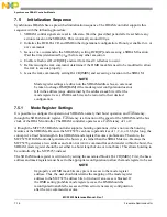
8.2.5
Chip Selects
Chip select CS1 is shared with QSPI_CS3 and GPIO28.
Power-on reset function of CS1/QSPI_CS3/GPIO28 is CS1
The function can be programmed in the Pin Configuration register.
Chip select CS0 shares with CS4.
Its default mode is dependent on the state of address pin A23 at power-on reset.
This is determined as follows:
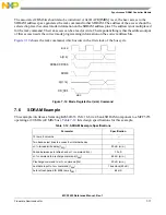
During power-on reset, logic level of pins A23 and A20/A24 are sensed. A pull-up / pull-down resistor
should be connected between these pins and VDD or GND. Depending whether a pull-up or pull-down is
mounted, different options are selected.
When the address decode matches one of the chip select spaces, the MCF5253 processor will pull low the
appropriate chip select low indicating an external bus access.
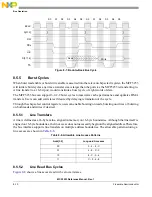
CS2 is also available but is associated with the IDE read and write strobes IDE_DIOR and IDE_DIOW.
Configuration registers for CS3 are present but no hardware pin exists for this CS on the MCF5253.
However it is possible to program BUFENB2 via the CS3 registers.
8.2.6
Output Enable
The OE pin on the MCF5253 will be pulled low during any read cycle from a device selected by CS0, CS1,
CS2, or CS4.
8.3
Clock and Reset Signals
These signals provide the external system interface for the MCF5253 (see
).
Table 8-3. Chip Select Settings
Pin
Description
A23
Pull-up: Boot from memory connected to CS0/CS4. CS0/CS4 function is CS0
Pull-down: Boot from on-chip boot ROM. CS0/CS4 function becomes CS4
Table 8-4. CF-Bus Signal Summary
Signal Name
Direction
Description
RSTI
In
Reset In
BCLK
Out
System Bus Clock Output (SYSCLK)
Содержание MCF5253
Страница 1: ...Document Number MCF5253RM Rev 1 08 2008 MCF5253 Reference Manual...
Страница 26: ...MCF5253 Reference Manual Rev 1 xxvi Freescale Semiconductor...
Страница 32: ...MCF5253 Reference Manual Rev 1 xxxii Freescale Semiconductor...
Страница 46: ...MCF5253 Introduction MCF5253 Reference Manual Rev 1 1 14 Freescale Semiconductor...
Страница 62: ...Signal Description MCF5253 Reference Manual Rev 1 2 16 Freescale Semiconductor...
Страница 98: ...Instruction Cache MCF5253 Reference Manual Rev 1 5 10 Freescale Semiconductor...
Страница 104: ...Static RAM SRAM MCF5253 Reference Manual Rev 1 6 6 Freescale Semiconductor...
Страница 128: ...Synchronous DRAM Controller Module MCF5253 Reference Manual Rev 1 7 24 Freescale Semiconductor...
Страница 144: ...Bus Operation MCF5253 Reference Manual Rev 1 8 16 Freescale Semiconductor...
Страница 176: ...System Integration Module SIM MCF5253 Reference Manual Rev 1 9 32 Freescale Semiconductor...
Страница 198: ...Analog to Digital Converter ADC MCF5253 Reference Manual Rev 1 12 6 Freescale Semiconductor...
Страница 246: ...DMA Controller MCF5253 Reference Manual Rev 1 14 18 Freescale Semiconductor...
Страница 282: ...UART Modules MCF5253 Reference Manual Rev 1 15 36 Freescale Semiconductor...
Страница 298: ...Queued Serial Peripheral Interface QSPI Module MCF5253 Reference Manual Rev 1 16 16 Freescale Semiconductor...
Страница 344: ...Audio Interface Module AIM MCF5253 Reference Manual Rev 1 17 46 Freescale Semiconductor...
Страница 362: ...I2 C Modules MCF5253 Reference Manual Rev 1 18 18 Freescale Semiconductor...
Страница 370: ...Boot ROM MCF5253 Reference Manual Rev 1 19 8 Freescale Semiconductor...


