


UART Modules
MCF5253 Reference Manual, Rev. 1
15-6
Freescale Semiconductor
.
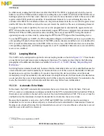
Figure 15-4. Transmitter and Receiver Functional Diagram
15.3.2.1
Transmitter
The transmitter is enabled through the UART command register (UCR) located within the UART module.
The UART module signals the CPU when it is ready to accept a character by setting the transmitter-ready
bit (TxRDY) in the UART status register (USR). Functional timing information for the transmitter is
shown in
.
The transmitter converts parallel data from the CPU to a serial bit stream on TxD. It automatically sends
a start bit followed by:
•
The programmed number of data bits
•
An optional parity bit
•
The programmed number of stop bits
The least significant bit is sent first. Data is shifted from the transmitter output on the falling edge of the
clock source.
After the transmission of the stop bits, if a new character is not available in the transmitter holding register,
the TxD output remains in the high (mark condition) state, and the transmitter-empty bit (TxEMP) in the
USR is set. Transmission resumes and the TxEMP bit is cleared when the CPU loads a new character into
the UART transmitter buffer (UTB). If the transmitter receives a disable command, it continues operating
until the character (if one is present) in the transmit-shift register is completely shifted out of transmitter
W
R
R/W
R/W
W
R
UART SERIAL CHANNEL
UART COMMAND REGISTER (UCR)
EXTERNAL INTERFACE
UART MODE REGISTER 1 (UMR1)
UART MODE REGISTER 2 (UMR2)
UART STATUS REGISTER (USR)
TRANSMIT HOLDING REGISTER
TRANSMIT SHIFT REGISTER
RECEIVER HOLDING REGISTER 1
RECEIVER HOLDING REGISTER 2
RECEIVER HOLDING REGISTER 3
RECEIVER SHIFT REGISTER
TRANSMIT
BUFFER (UTB)
(2 REGISTERS)
RECEIVE
BUFFER (URB)
(4 REGISTERS)
FIFO
TXD
RXD
Содержание MCF5253
Страница 1: ...Document Number MCF5253RM Rev 1 08 2008 MCF5253 Reference Manual...
Страница 26: ...MCF5253 Reference Manual Rev 1 xxvi Freescale Semiconductor...
Страница 32: ...MCF5253 Reference Manual Rev 1 xxxii Freescale Semiconductor...
Страница 46: ...MCF5253 Introduction MCF5253 Reference Manual Rev 1 1 14 Freescale Semiconductor...
Страница 62: ...Signal Description MCF5253 Reference Manual Rev 1 2 16 Freescale Semiconductor...
Страница 98: ...Instruction Cache MCF5253 Reference Manual Rev 1 5 10 Freescale Semiconductor...
Страница 104: ...Static RAM SRAM MCF5253 Reference Manual Rev 1 6 6 Freescale Semiconductor...
Страница 128: ...Synchronous DRAM Controller Module MCF5253 Reference Manual Rev 1 7 24 Freescale Semiconductor...
Страница 144: ...Bus Operation MCF5253 Reference Manual Rev 1 8 16 Freescale Semiconductor...
Страница 176: ...System Integration Module SIM MCF5253 Reference Manual Rev 1 9 32 Freescale Semiconductor...
Страница 198: ...Analog to Digital Converter ADC MCF5253 Reference Manual Rev 1 12 6 Freescale Semiconductor...
Страница 246: ...DMA Controller MCF5253 Reference Manual Rev 1 14 18 Freescale Semiconductor...
Страница 282: ...UART Modules MCF5253 Reference Manual Rev 1 15 36 Freescale Semiconductor...
Страница 298: ...Queued Serial Peripheral Interface QSPI Module MCF5253 Reference Manual Rev 1 16 16 Freescale Semiconductor...
Страница 344: ...Audio Interface Module AIM MCF5253 Reference Manual Rev 1 17 46 Freescale Semiconductor...
Страница 362: ...I2 C Modules MCF5253 Reference Manual Rev 1 18 18 Freescale Semiconductor...
Страница 370: ...Boot ROM MCF5253 Reference Manual Rev 1 19 8 Freescale Semiconductor...


