


Universal Serial Bus Interface
MCF5253 Reference Manual, Rev. 1
24-80
Freescale Semiconductor
to the Asynchronous Schedule Enable bit in the USBCMD register. The software then can poll the
Asynchronous Schedule Status bit to determine when the asynchronous schedule has made the desired
transition. The software must not modify the Asynchronous Schedule Enable bit unless the value of the
Asynchronous Schedule Enable bit equals that of the Asynchronous Schedule Status bit.
The asynchronous schedule is used to manage all Control and Bulk transfers. Control and Bulk transfers
are managed using queue head data structures. The asynchronous schedule is based at the
ASYNCLISTADDR register. The default value of the ASYNCLISTADDR register after reset is undefined
and the schedule is disabled when the Asynchronous Schedule Enable bit is cleared.
The software may only write this register with defined results when the schedule is disabled, for example,
Asynchronous Schedule Enable bit in the USBCMD and the Asynchronous Schedule Status bit in the
USBSTS register are cleared. The system software enables execution from the asynchronous schedule by
writing a valid memory address (of a queue head) into this register. Then the software enables the
asynchronous schedule by setting the Asynchronous Schedule Enable bit is set. The asynchronous
schedule is actually enabled when the Asynchronous Schedule Status bit is set.
When the host controller begins servicing the asynchronous schedule, it begins by using the value of the
ASYNCLISTADDR register. It reads the first referenced data structure and begins executing transactions
and traversing the linked list as appropriate. When the host controller completes processing the
asynchronous schedule, it retains the value of the last accessed queue head's horizontal pointer in the
ASYNCLISTADDR register. Next time the asynchronous schedule is accessed, this is the first data
structure that is serviced. This provides round-robin fairness for processing the asynchronous schedule.
A host controller completes processing the asynchronous schedule when one of the following events
occur:
•
The end of a micro-frame occurs.
•
The host controller detects an empty list condition.
•
The schedule has been disabled via the Asynchronous Schedule Enable bit in the USBCMD
register.
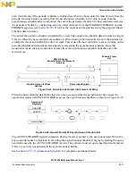
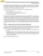
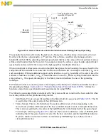
The queue heads in the asynchronous list are linked into a simple circular list as shown in
Queue head data structures are the only valid data structures that may be linked into the asynchronous
schedule. An isochronous transfer descriptor (iTD or siTD) in the asynchronous schedule yields undefined
results.
The maximum packet size field in a queue head is sized to accommodate the use of this data structure for
all non-isochronous transfer types. The USB Specification, Revision 2.0 specifies the maximum packet
sizes for all transfer types and transfer speeds. The system software should always parameterize the queue
head data structures according to the core specification requirements.
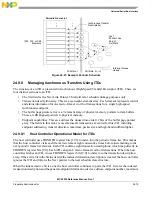
24.9.9.1
Adding Queue Heads to Asynchronous Schedule
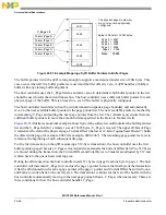
This is a software requirement section. There are two independent events for adding queue heads to the
asynchronous schedule. The first is the initial activation of the asynchronous list. The second is inserting
a new queue head into an activated asynchronous list.
Содержание MCF5253
Страница 1: ...Document Number MCF5253RM Rev 1 08 2008 MCF5253 Reference Manual...
Страница 26: ...MCF5253 Reference Manual Rev 1 xxvi Freescale Semiconductor...
Страница 32: ...MCF5253 Reference Manual Rev 1 xxxii Freescale Semiconductor...
Страница 46: ...MCF5253 Introduction MCF5253 Reference Manual Rev 1 1 14 Freescale Semiconductor...
Страница 62: ...Signal Description MCF5253 Reference Manual Rev 1 2 16 Freescale Semiconductor...
Страница 98: ...Instruction Cache MCF5253 Reference Manual Rev 1 5 10 Freescale Semiconductor...
Страница 104: ...Static RAM SRAM MCF5253 Reference Manual Rev 1 6 6 Freescale Semiconductor...
Страница 128: ...Synchronous DRAM Controller Module MCF5253 Reference Manual Rev 1 7 24 Freescale Semiconductor...
Страница 144: ...Bus Operation MCF5253 Reference Manual Rev 1 8 16 Freescale Semiconductor...
Страница 176: ...System Integration Module SIM MCF5253 Reference Manual Rev 1 9 32 Freescale Semiconductor...
Страница 198: ...Analog to Digital Converter ADC MCF5253 Reference Manual Rev 1 12 6 Freescale Semiconductor...
Страница 246: ...DMA Controller MCF5253 Reference Manual Rev 1 14 18 Freescale Semiconductor...
Страница 282: ...UART Modules MCF5253 Reference Manual Rev 1 15 36 Freescale Semiconductor...
Страница 298: ...Queued Serial Peripheral Interface QSPI Module MCF5253 Reference Manual Rev 1 16 16 Freescale Semiconductor...
Страница 344: ...Audio Interface Module AIM MCF5253 Reference Manual Rev 1 17 46 Freescale Semiconductor...
Страница 362: ...I2 C Modules MCF5253 Reference Manual Rev 1 18 18 Freescale Semiconductor...
Страница 370: ...Boot ROM MCF5253 Reference Manual Rev 1 19 8 Freescale Semiconductor...


