


Boot ROM
MCF5253 Reference Manual, Rev. 1
19-4
Freescale Semiconductor
19.2.3
Serial Boot Data Format
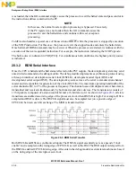
All serial boot modes use the same data structure to read data from the external device. All data is
organized in boot records. The boot loader reads one or more boot records and processes the data according
to the command which is supplied in the boot record header. A boot record has the following structure:
The first byte of a boot record is a sync byte with value 0x55. The boot-loader will ignore all data up to
and including this byte. The second byte contains the command to execute and the data width of the
data/code section. The command is coded in the upper nibble; the size is coded in the lower nibble. The
size specification defines the word length to be used to store the data in the MCF5253 memory space. This
allows writing to registers through the boot loader.
The following tables describe the encoding of the command and size bits:
19.2.3.1
Command Encoding/Size Encoding
The destination address is the base address for the data in the boot record. Data will be stored sequentially
starting at this address.
The Byte Count (BC) is the number of data bytes in the boot record. After the loader has read the number
of bytes specified, it assumes the next byte to be the start of a new record.
The data/code section in a command block contains the actual data to be written. This section can be empty
(BC=0). Typically used to start program execution at the address specified in the address field.
Table 19-2. Boot Records
Offset
# Bytes
Description
0
1
Sync Byte (0x55)
1
1
Command/Data width (byte, word, longword)
2
4
Destination address in MCF5253 memory space
6
4
Number of bytes in data/code section (BC)
10
BC
Data/Code section
Table 19-3. Command Bits
Command
Code
Store Immediate
0b0001
Execute
0b0011
Table 19-4. Size Bits
Size
Code
Byte
0b0001
Word
0b0010
Long Word
0b0100
Содержание MCF5253
Страница 1: ...Document Number MCF5253RM Rev 1 08 2008 MCF5253 Reference Manual...
Страница 26: ...MCF5253 Reference Manual Rev 1 xxvi Freescale Semiconductor...
Страница 32: ...MCF5253 Reference Manual Rev 1 xxxii Freescale Semiconductor...
Страница 46: ...MCF5253 Introduction MCF5253 Reference Manual Rev 1 1 14 Freescale Semiconductor...
Страница 62: ...Signal Description MCF5253 Reference Manual Rev 1 2 16 Freescale Semiconductor...
Страница 98: ...Instruction Cache MCF5253 Reference Manual Rev 1 5 10 Freescale Semiconductor...
Страница 104: ...Static RAM SRAM MCF5253 Reference Manual Rev 1 6 6 Freescale Semiconductor...
Страница 128: ...Synchronous DRAM Controller Module MCF5253 Reference Manual Rev 1 7 24 Freescale Semiconductor...
Страница 144: ...Bus Operation MCF5253 Reference Manual Rev 1 8 16 Freescale Semiconductor...
Страница 176: ...System Integration Module SIM MCF5253 Reference Manual Rev 1 9 32 Freescale Semiconductor...
Страница 198: ...Analog to Digital Converter ADC MCF5253 Reference Manual Rev 1 12 6 Freescale Semiconductor...
Страница 246: ...DMA Controller MCF5253 Reference Manual Rev 1 14 18 Freescale Semiconductor...
Страница 282: ...UART Modules MCF5253 Reference Manual Rev 1 15 36 Freescale Semiconductor...
Страница 298: ...Queued Serial Peripheral Interface QSPI Module MCF5253 Reference Manual Rev 1 16 16 Freescale Semiconductor...
Страница 344: ...Audio Interface Module AIM MCF5253 Reference Manual Rev 1 17 46 Freescale Semiconductor...
Страница 362: ...I2 C Modules MCF5253 Reference Manual Rev 1 18 18 Freescale Semiconductor...
Страница 370: ...Boot ROM MCF5253 Reference Manual Rev 1 19 8 Freescale Semiconductor...


