


Universal Serial Bus Interface
MCF5253 Reference Manual, Rev. 1
Freescale Semiconductor
24-57
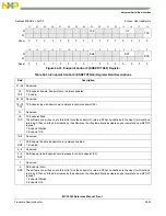
Queue Element Transfer Descriptors must be aligned on 32-byte boundaries.
24.8.5.1
Next qTD Pointer
The first DWord of an element transfer descriptor is a pointer to another transfer element descriptor.
24.8.5.2
Alternate Next qTD Pointer
The second DWord of a queue element transfer descriptor is used to support hardware-only advance of the
data stream to the next client buffer on short packet. To be more explicit the host controller will always use
this pointer when the current qTD is retired due to short packet.
31
30
29
28
27
26
25
24
23
22
21
20
19
18
17
16
15
14
13
12
11
10
9
8
7
6
5
4
3
2
1
0
Offset
Next qTD Pointer
0000
T
0x00
Alternate Next qTD Pointer
0000
T
0x04
dt
1
1
Host controller read/write; all others read-only.
Total Bytes to Transfer
ioc C_Page
Cerr
PID
Code
Status
0x08
Buffer Pointer (Page 0)
Current Offset
0x0C
Buffer Pointer (Page 1)
0000_0000_0000
0x10
Buffer Pointer (Page 2)
0000_0000_0000
0x14
Buffer Pointer (Page 3)
0000_0000_0000
0x18
Buffer Pointer (Page 4)
0000_0000_0000
0x1C
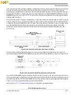
Figure 24-40. Queue Element Transfer Descriptor (qTD)
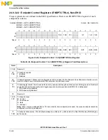
Table 24-51. qTD Next Element Transfer Pointer (DWord 0)
Bit
Name
Description
31–5 Next qTD
Pointer
This field contains the physical memory address of the next qTD to be processed. The field corresponds to
memory address signals[31–5], respectively.
4–1
–
Reserved. These bits are reserved and their value has no effect on operation.
0
T
Terminate. This bit indicates to the Host Controller that there are no more valid entries in the queue.
0 Pointer is valid (points to a valid Transfer Element Descriptor).
1 Pointer is invalid.
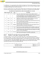
Table 24-52. qTD Alternate Next Element Transfer Pointer (DWord 1)
Bit
Name
Description
31–5 Alternate Next
qTD Pointer
This field contains the physical memory address of the next qTD to be processed in the event that the
current qTD execution encounters a short packet (for an IN transaction). The field corresponds to
memory address signals [31–5], respectively.
Содержание MCF5253
Страница 1: ...Document Number MCF5253RM Rev 1 08 2008 MCF5253 Reference Manual...
Страница 26: ...MCF5253 Reference Manual Rev 1 xxvi Freescale Semiconductor...
Страница 32: ...MCF5253 Reference Manual Rev 1 xxxii Freescale Semiconductor...
Страница 46: ...MCF5253 Introduction MCF5253 Reference Manual Rev 1 1 14 Freescale Semiconductor...
Страница 62: ...Signal Description MCF5253 Reference Manual Rev 1 2 16 Freescale Semiconductor...
Страница 98: ...Instruction Cache MCF5253 Reference Manual Rev 1 5 10 Freescale Semiconductor...
Страница 104: ...Static RAM SRAM MCF5253 Reference Manual Rev 1 6 6 Freescale Semiconductor...
Страница 128: ...Synchronous DRAM Controller Module MCF5253 Reference Manual Rev 1 7 24 Freescale Semiconductor...
Страница 144: ...Bus Operation MCF5253 Reference Manual Rev 1 8 16 Freescale Semiconductor...
Страница 176: ...System Integration Module SIM MCF5253 Reference Manual Rev 1 9 32 Freescale Semiconductor...
Страница 198: ...Analog to Digital Converter ADC MCF5253 Reference Manual Rev 1 12 6 Freescale Semiconductor...
Страница 246: ...DMA Controller MCF5253 Reference Manual Rev 1 14 18 Freescale Semiconductor...
Страница 282: ...UART Modules MCF5253 Reference Manual Rev 1 15 36 Freescale Semiconductor...
Страница 298: ...Queued Serial Peripheral Interface QSPI Module MCF5253 Reference Manual Rev 1 16 16 Freescale Semiconductor...
Страница 344: ...Audio Interface Module AIM MCF5253 Reference Manual Rev 1 17 46 Freescale Semiconductor...
Страница 362: ...I2 C Modules MCF5253 Reference Manual Rev 1 18 18 Freescale Semiconductor...
Страница 370: ...Boot ROM MCF5253 Reference Manual Rev 1 19 8 Freescale Semiconductor...


