


Issue 1.2
UNIVERGE SV9100
4 - 104
Installing the SV9100 Blades
2. User removes Add-on board and moves it to slot 6.
The re-inserted board automatically gets ports
17 ~ 24 (9 ~ 16 are unavailable).
.
User can erase the ports 9 ~ 16.
.
Then reinsert the board in slot 6 to get ports 9 ~ 16.
3. User relocates the Main board to slot 4.
None of the port numbers change. However, the
programming in Program 10-55 must be changed to
reflect this move.
The grouping of the three GSWU units to form a 20 port
switch is restricted to reside in a single system location. The
grouping is not allowed where the GSWU units are placed
as part of the NetLink feature in the Univerge SV9100
system.
6.4.2.5
Unmanaged Switch Functions
In the unmanaged mode, a GSWU unit will have the
following functions only:
10/100/1000 Ethernet ports (x8)
PoE Class 3 (lowest power class)
6.4.3
LED Indications
6.4.4
Connectors
Backplane Connector – J1 connection to system CPU board and
other boards in the chassis.
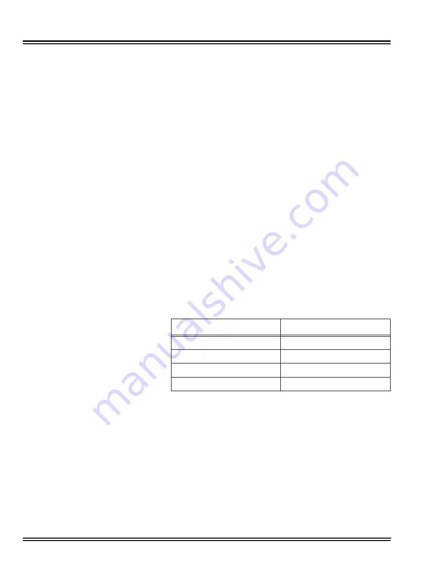
Table 4-49 CD-ETIA
LED Indications
Port State
LED Display
1000Mbps Link
Green Solid
10/100Mbps Link
Yellow Solid
No Link
Off
Port Activity
LED Blinking
Содержание Univerge SV9100
Страница 1: ...System Hardware Manual Issue 1 2 January 2015...
Страница 2: ...THIS PAGE INTENTIONALLY LEFT BLANK...
Страница 40: ...Issue 1 2 UNIVERGE SV9100 1 16 Introduction to SV9100...
Страница 44: ...Issue 1 2 UNIVERGE SV9100 2 4 SV9100 System Specifications Figure 2 1 SV9100 System Block Diagram...
Страница 100: ...Issue 1 2 UNIVERGE SV9100 3 28 Installing the SV9100 Chassis Figure 3 36 Anchor Bolt from Wall 9 5 Chassis...
Страница 105: ...UNIVERGE SV9100 Issue 1 2 System Hardware Manual 3 33 Figure 3 42 Brackets Small Batt Box...
Страница 154: ...Issue 1 2 UNIVERGE SV9100 3 82 Installing the SV9100 Chassis...
Страница 185: ...UNIVERGE SV9100 Issue 1 2 System Hardware Manual 4 31 Figure 4 8 Connecting a IPLA Daughter Board to a Network PC...
Страница 199: ...UNIVERGE SV9100 Issue 1 2 System Hardware Manual 4 45 Figure 4 12 Installing the GPZ 4LCA Daughter Board...
Страница 239: ...UNIVERGE SV9100 Issue 1 2 System Hardware Manual 4 85 Figure 4 24 Control Signal Connection...
Страница 259: ...UNIVERGE SV9100 Issue 1 2 System Hardware Manual 4 105 NOTES...
Страница 260: ...Issue 1 2 UNIVERGE SV9100 4 106 Installing the SV9100 Blades...
Страница 325: ...UNIVERGE SV9100 Issue 1 2 System Hardware Manual 5 65 Figure 5 57 Sticker Braille L KIT Sheet 2...
Страница 412: ...Issue 1 2 UNIVERGE SV9100 5 152 Installing DT Series Digital and IP Multiline Terminals...
Страница 418: ...Issue 1 2 UNIVERGE SV9100 6 6 Installing SV9100 Optional Equipment Figure 6 5 PGD 2 U10 ADP Connection Diagram...
Страница 425: ...UNIVERGE SV9100 Issue 1 2 System Hardware Manual 6 13 Figure 6 11 Setting the PGD 2 U10 ADP for a Door Box...
Страница 426: ...Issue 1 2 UNIVERGE SV9100 6 14 Installing SV9100 Optional Equipment Figure 6 12 Installing a Door Box...
Страница 438: ...Issue 1 2 UNIVERGE SV9100 6 26 Installing SV9100 Optional Equipment Figure 6 17 PGD 2 U10 ADP Connections...
Страница 475: ...UNIVERGE SV9100 Issue 1 2 System Hardware Manual 6 63 Figure 6 64 Power Failure Connector CN3 Shown on GCD 4COTA Blade...
Страница 476: ...Issue 1 2 UNIVERGE SV9100 6 64 Installing SV9100 Optional Equipment...
Страница 477: ...THIS PAGE IS INTENTIONALLY LEFT BLANK...


