UNIVERGE SV9100
Issue 1.2
System Hardware Manual
3 - 5
1.1.2.1
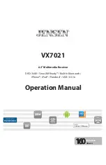
Connector Pin-Out on the GPZ-BS10/GPZ-BS11
1.1.2.2
Install the GPZ-BS10 Expansion Base Blade in the
CHS2UG Controlling Chassis
1.
Ensure the chassis is powered down.
2.
Locate the door positioned on the left end (expansion bay) of
the Controlling Chassis (refer to
Figure 3-7 GPZ-BS10
Expansion Bay in Controlling Chassis on page 3-6
).
Table 3-1 GPZ-BS10/GPZ-BS11 Connector Pin-Out
RJ-61 Cable Connector
GPZ-BS10
– CN2, CN3, CN 4
GPZ-BS11 – CN3
Pin No.
Connection
1
HW_UP (+)
2
HW_UP (-)
3
HW_DWN (+)
4
FS (+)
5
FS (-)
6
HW_DWN (-)
7
CK8M (+)
8
CK8M (-)
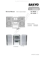
Figure 3-6 GPZ-BS10 Components
Do not remove or install this blade with the
power on.
Содержание Univerge SV9100
Страница 1: ...System Hardware Manual Issue 1 2 January 2015...
Страница 2: ...THIS PAGE INTENTIONALLY LEFT BLANK...
Страница 40: ...Issue 1 2 UNIVERGE SV9100 1 16 Introduction to SV9100...
Страница 44: ...Issue 1 2 UNIVERGE SV9100 2 4 SV9100 System Specifications Figure 2 1 SV9100 System Block Diagram...
Страница 100: ...Issue 1 2 UNIVERGE SV9100 3 28 Installing the SV9100 Chassis Figure 3 36 Anchor Bolt from Wall 9 5 Chassis...
Страница 105: ...UNIVERGE SV9100 Issue 1 2 System Hardware Manual 3 33 Figure 3 42 Brackets Small Batt Box...
Страница 154: ...Issue 1 2 UNIVERGE SV9100 3 82 Installing the SV9100 Chassis...
Страница 185: ...UNIVERGE SV9100 Issue 1 2 System Hardware Manual 4 31 Figure 4 8 Connecting a IPLA Daughter Board to a Network PC...
Страница 199: ...UNIVERGE SV9100 Issue 1 2 System Hardware Manual 4 45 Figure 4 12 Installing the GPZ 4LCA Daughter Board...
Страница 239: ...UNIVERGE SV9100 Issue 1 2 System Hardware Manual 4 85 Figure 4 24 Control Signal Connection...
Страница 259: ...UNIVERGE SV9100 Issue 1 2 System Hardware Manual 4 105 NOTES...
Страница 260: ...Issue 1 2 UNIVERGE SV9100 4 106 Installing the SV9100 Blades...
Страница 325: ...UNIVERGE SV9100 Issue 1 2 System Hardware Manual 5 65 Figure 5 57 Sticker Braille L KIT Sheet 2...
Страница 412: ...Issue 1 2 UNIVERGE SV9100 5 152 Installing DT Series Digital and IP Multiline Terminals...
Страница 418: ...Issue 1 2 UNIVERGE SV9100 6 6 Installing SV9100 Optional Equipment Figure 6 5 PGD 2 U10 ADP Connection Diagram...
Страница 425: ...UNIVERGE SV9100 Issue 1 2 System Hardware Manual 6 13 Figure 6 11 Setting the PGD 2 U10 ADP for a Door Box...
Страница 426: ...Issue 1 2 UNIVERGE SV9100 6 14 Installing SV9100 Optional Equipment Figure 6 12 Installing a Door Box...
Страница 438: ...Issue 1 2 UNIVERGE SV9100 6 26 Installing SV9100 Optional Equipment Figure 6 17 PGD 2 U10 ADP Connections...
Страница 475: ...UNIVERGE SV9100 Issue 1 2 System Hardware Manual 6 63 Figure 6 64 Power Failure Connector CN3 Shown on GCD 4COTA Blade...
Страница 476: ...Issue 1 2 UNIVERGE SV9100 6 64 Installing SV9100 Optional Equipment...
Страница 477: ...THIS PAGE IS INTENTIONALLY LEFT BLANK...