


UNIVERGE SV9100
Issue 1.2
System Hardware Manual
4 - 23
3.1.3
Switch Settings
Refer to
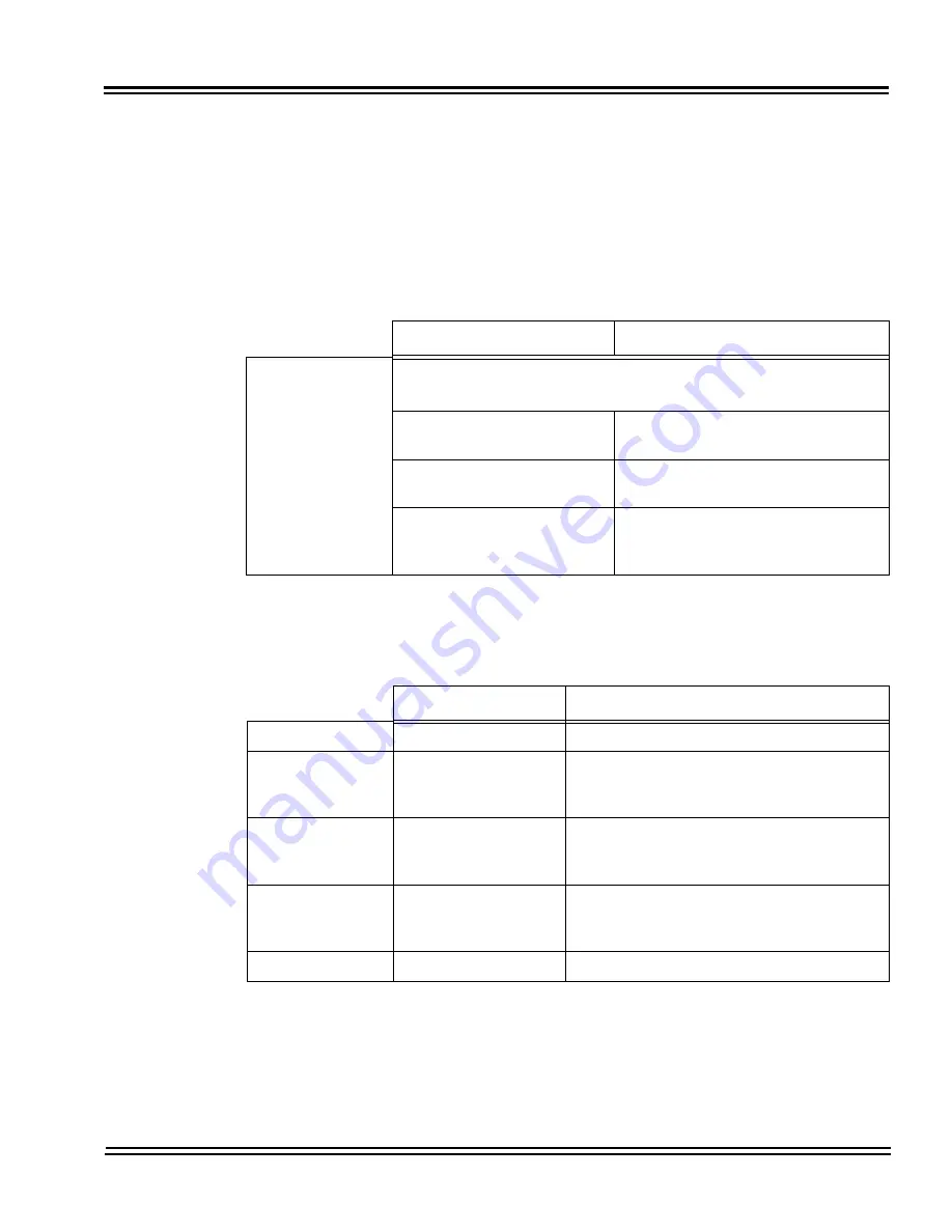
Table 4-6 GCD-CP10 Switch Settings
for system restart/
system reset and with system power on.
Figure 4-3 GCD-CP10
Blade Layout on page 4-16
shows the location of the SW1 switch on
the GCD-CP10
blade.
3.1.4
LED Indications
The LEDs on the CPU indicate the following:
Table 4-6 GCD-CP10 Switch Settings
USB Memory Status
Operation
Switch
S5 - Load Switch
With a system restart or a system reset while holding the SW1
switch:
When USB Memory is not
installed:
Cold Start occurs.
When USB Memory is
installed:
USB Memory contents loaded.
When an unauthorized USB
device is installed:
System does not start and an “Illegal
USB device is connected” alarm is
recorded.
Table 4-7 GCD-CP10 Switch 6 Settings
Configuration
Note
SW4-1
ON
Not Used
SW4-2
OFF
Test Mode
ON = Test Mode
OFF = Normal
SW4-3
OFF
RS232C Select
ON = Use
OFF = Not Used
SW4-4
ON
Reset Configuration
ON = Normal
OFF = ICE Mode
S6
SENSE switch
Not Used
Содержание Univerge SV9100
Страница 1: ...System Hardware Manual Issue 1 2 January 2015...
Страница 2: ...THIS PAGE INTENTIONALLY LEFT BLANK...
Страница 40: ...Issue 1 2 UNIVERGE SV9100 1 16 Introduction to SV9100...
Страница 44: ...Issue 1 2 UNIVERGE SV9100 2 4 SV9100 System Specifications Figure 2 1 SV9100 System Block Diagram...
Страница 100: ...Issue 1 2 UNIVERGE SV9100 3 28 Installing the SV9100 Chassis Figure 3 36 Anchor Bolt from Wall 9 5 Chassis...
Страница 105: ...UNIVERGE SV9100 Issue 1 2 System Hardware Manual 3 33 Figure 3 42 Brackets Small Batt Box...
Страница 154: ...Issue 1 2 UNIVERGE SV9100 3 82 Installing the SV9100 Chassis...
Страница 185: ...UNIVERGE SV9100 Issue 1 2 System Hardware Manual 4 31 Figure 4 8 Connecting a IPLA Daughter Board to a Network PC...
Страница 199: ...UNIVERGE SV9100 Issue 1 2 System Hardware Manual 4 45 Figure 4 12 Installing the GPZ 4LCA Daughter Board...
Страница 239: ...UNIVERGE SV9100 Issue 1 2 System Hardware Manual 4 85 Figure 4 24 Control Signal Connection...
Страница 259: ...UNIVERGE SV9100 Issue 1 2 System Hardware Manual 4 105 NOTES...
Страница 260: ...Issue 1 2 UNIVERGE SV9100 4 106 Installing the SV9100 Blades...
Страница 325: ...UNIVERGE SV9100 Issue 1 2 System Hardware Manual 5 65 Figure 5 57 Sticker Braille L KIT Sheet 2...
Страница 412: ...Issue 1 2 UNIVERGE SV9100 5 152 Installing DT Series Digital and IP Multiline Terminals...
Страница 418: ...Issue 1 2 UNIVERGE SV9100 6 6 Installing SV9100 Optional Equipment Figure 6 5 PGD 2 U10 ADP Connection Diagram...
Страница 425: ...UNIVERGE SV9100 Issue 1 2 System Hardware Manual 6 13 Figure 6 11 Setting the PGD 2 U10 ADP for a Door Box...
Страница 426: ...Issue 1 2 UNIVERGE SV9100 6 14 Installing SV9100 Optional Equipment Figure 6 12 Installing a Door Box...
Страница 438: ...Issue 1 2 UNIVERGE SV9100 6 26 Installing SV9100 Optional Equipment Figure 6 17 PGD 2 U10 ADP Connections...
Страница 475: ...UNIVERGE SV9100 Issue 1 2 System Hardware Manual 6 63 Figure 6 64 Power Failure Connector CN3 Shown on GCD 4COTA Blade...
Страница 476: ...Issue 1 2 UNIVERGE SV9100 6 64 Installing SV9100 Optional Equipment...
Страница 477: ...THIS PAGE IS INTENTIONALLY LEFT BLANK...


