4-46
Upgrading Your System
6.
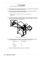
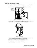
Feed the cables of the replacement LED assembly through the mounting holes in the front and
side of the chassis.
7.
Insert the bottom tab of the LED assembly into mounting hole in the front of the chassis and
while pushing downward on the top tab of the LED assembly, snap the LED assembly into
place.
8.
Connect the power and hard disk drive LED cables to the system board connectors. The power
LED cable is green and black; insert the connector so that the green wire is above the black
wire. The hard disk drive LED cable is red and black; insert the connector so that the red wire
is above the black wire.
9.
Install the front panel as described earlier in this chapter.
10.
Install the side panels as described earlier in this chapter.
11.
Power on the system.
Содержание EXPRESS 5800 ES1400 SERIES Online
Страница 1: ...EXPRESS5800 ES1400 SERIES ONLINE SERVICE GUIDE...
Страница 8: ...Using This Guide xv...
Страница 21: ......
Страница 33: ...2 12 Setting Up the System...
Страница 60: ...Configuring Your System 3 27...
Страница 130: ...Problem Solving 5 21...
Страница 131: ......
Страница 132: ......
Страница 142: ...6 10 Illustrated Parts Breakdown...
Страница 143: ...A System Cabling n Before You Begin n Static Precautions n Standard Configuration n RAID Configuration...
Страница 149: ...System Cabling A 7 WIDE SCSI CABLE 68 pins IDE CABLE 40 pins Standard System Cable Routing...
Страница 152: ...B System Setup Utility n System Setup Utility SSU n Creating SSU Diskettes n Running the SSU n Exiting the SSU...
Страница 160: ...System Setup Utility B 9 Adding and Removing ISA Cards Window...
Страница 163: ...B 12 System Setup Utility System Resource Usage Window...

