© 2014 MIMAKI ENGINEERING CO.,LTD.
7.1.2
P.4
7.1.2 List of Error Messages
1
2
3
4
5
6
7
8
42
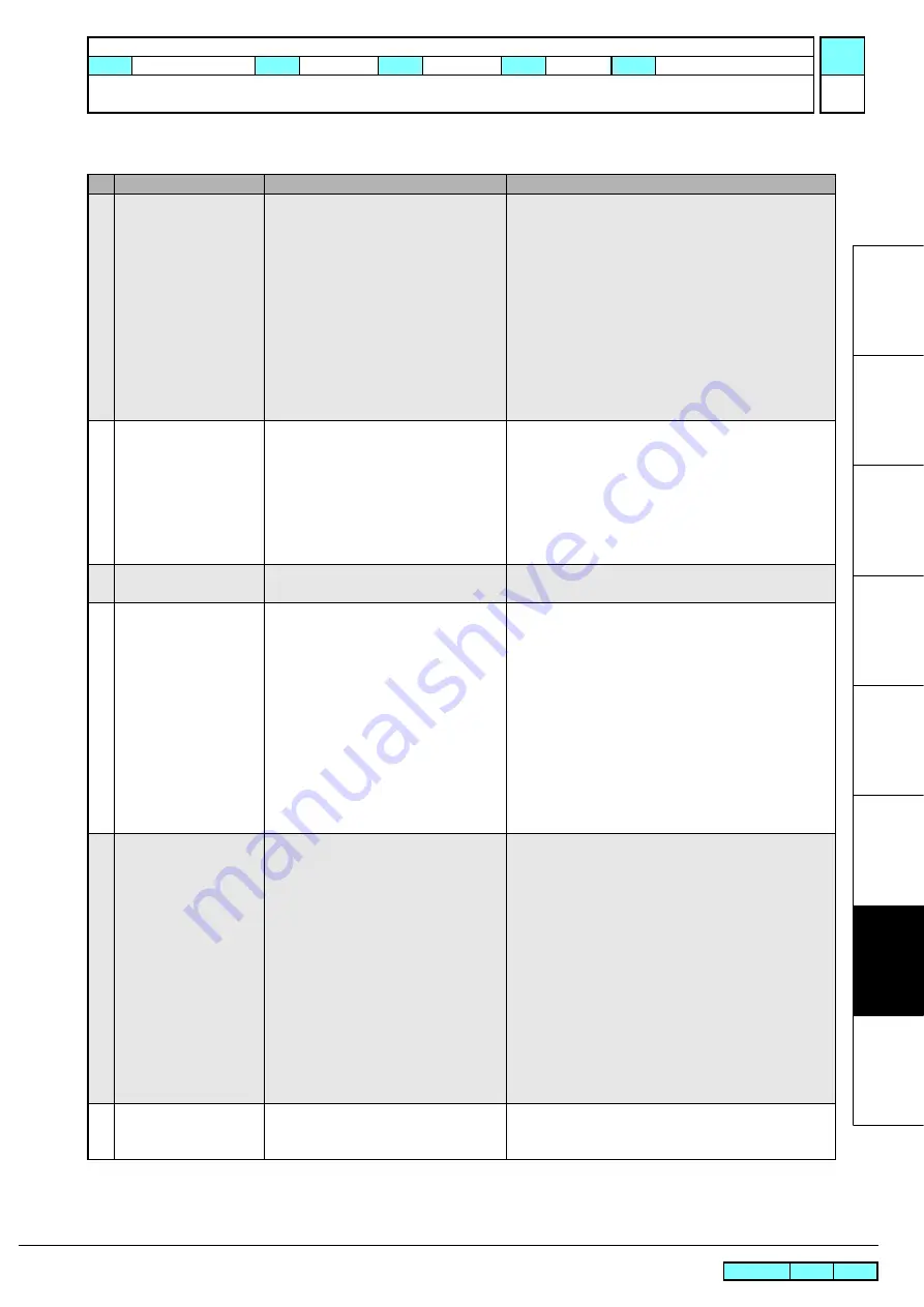
ERROR 429
Take-up Limit DETECT
Limit position of tension bar
(A tension bar deviated from the highest
control position for a certain time.)
When the upper limit of control range
exceeds for a certain time, the error occurs.
The operations after the error outbreak are
as follows.
→
In case that torque limiter is available,
control the take-up unit.
→
In case that torque limiter is not
available, slow acceleration and retry
(twice).
1. Check the setting status of the media.
2. Confirm that tension bar is risen by taking up the media
with manual SW. (If it is not risen, adjust the weights.)
3. Execute and confirm [#TEST][SENSOR][TAKE-UP
SLIT-A], [TAKE-UP SLIT-B].(Confirm that the ON/
OFF display is switched by moving the tension bar up
and down.)
4. Check the connector connection of Take-up tension
bar origin sensor and cable.
5. Replace the Take-up tension bar origin sensor.
43
ERROR 44f
Take-UP Roll Sns Err
Take-up shaft sensor is abnormal (Take-up
shaft sensor can not be read exactly.)
It occurs under conditions of follows;
・
When take-up shaft sensor does not work
・
When detection of take up diameter fails
Update of the take up diameter is not per-
formed after error occurs.
1. Execute and confirm [#TEST][SENSOR] [Torque
Limiter].(Confirm that the ON/OFF display is
switched by moving the tension bar up and down.)
2. Check the connector connection of Take-up tension
bar origin sensor and cable.
3. Replace the Take-up tension bar origin sensor.
44
ERROR 505
MEDIA JAM
The media jam sensor reacted.
1. Remove the media that hit it, and reset the media.
2. Execute [#TEST SENSOR] ->[MEDIA JAM]
.
45
ERROR 509
HDC POSCNT
HDC position counter error
1. Execute and confirm [#TEST][SENSOR]
[Y-ORIGIN].(Confirm that the ON/OFF display is
switched by moving the carriage left and right.)
2. Execute [#TEST][CHECK ENCODER].
3. Check the assembly of Y-scale, and confirm that there
is neither dirt nor scratch.
4. Check in manual if the Head Assy. (carriage) moves
left and right smoothly.
5. Check the connector connection of Y-origin Sensor
and Linear Encoder.
6. Replace the Y-origin Sensor or Linear Encoder with a
new one.
7. Check the assembly and connector connection of Y-
axis Motor.
46
ERROR 50a
Y ORIGIN
Y-origin error
(Origin of Y-axis can not be detected)
1. Execute and confirm [#TEST][SENSOR]
[Y-ORIGIN]
.
(Confirm that the ON/OFF display is
switched by moving the carriage left and right.)
2. Execute [#TEST][CHECK ENCODER].
3. Check in manual if the Head Assy. (carriage) moves
left and right smoothly.
4. Check the connector connection of Y-origin Sensor
and Linear Encoder.
5. Replace the Y-origin Sensor or Linear Encoder with a
new one.
6. Check the assembly and connector connection of Y-
axis Motor.
7. Replace the Y-axis Motor with a new one.
(Refer to
3.2.2)
8. Replace the MAIN PCB with a new one.
(Refer to
3.3.1)
47
ERROR 50c
MEDIA WIDTH SENSOR
The media width could not be read
correctly.
1. Check the media setting position.
2. Perform cleaning of the media width sensor.
3. Execute [#TEST][PAPER SENSOR].
List of Error Messages (4/7)
No.
LCD
Cause
List of Countermeasures
R.1.0
MAINTENANCE MANUAL > Troubleshooting > Details on Errors and Malfunctions > List of Error Messages
Model
JV300-130/160
Issued 2014.05.30 Revised
F/W ver
1.10
Remark
1.0
Rev.


