© 2014 MIMAKI ENGINEERING CO.,LTD.
4.2.3
P.2
4.2.3 DROP.POS
1
2
3
4
5
6
7
8
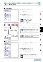
Forward adjustment
5. Select “SiDir” on the [SELECT] display.
[
] / [
] : Switches
[ENTER] : Confirms (Next)
6. Press the [ENTER] key to draw the pattern.
[ENTER] : To start Pattern drawing
[
] : To the compensation display
(Without drawing)
7. Check and compensate the patterns.
Input the adjustment value (the measured value:
μ
m) so that the
impact dots of the H2A line is at the same position in the Y-
direction, referring to the reference nozzle H1A line.
[
] / [
] : Compensating value input (Input unit:
20 µm
)
[ENTER] : Confirms (Next)
8. When compensated, draw and check the patterns again.
Return adjustment
9. On the [SELECT] display, select “ReDir”, and adjust it in the
same way as “SiDir”.
[
] / [
] : Switches
[ENTER] : Confirms (Next)
10. Press the [ENTER] key to draw the pattern.
[ENTER] : To start Pattern drawing
[
] : To the compensation display
(Without drawing)
11. When compensated, draw and check the patterns again.
#PRINT ADJUST
SELECT :SiDir
#PRINT ADJUST
SiDir :PRINT
Pattern drawing
ReDir
BiDir
#PRINT ADJUST
SELECT :SiDir
Adjust the followings for all.
WF3 : 540, 720, 1440 dpi
WF4 : 360, 540 dpi
360Std SiDir WF3
H1A-H2A : 0.0
-99.9~99.9
Magnify by a microscope, and
measure it in inside readings.
Input the compensating value, referring to the left
figure, if the displacement on the drop position of
head applied for the compensation occurs either right
or left against the reference head.
Repeat “Drawing -> Checking (Compensating)” until
any compensation is not required.
#PRINT ADJUST
SELECT:ReDir
#PRINT ADJUST
ReDir:PRINT
Pattern drawing
SiDir
BiDir
#PRINT ADJUST
SELECT :ReDir
360Std ReDir WF3
H1A-H2A : 0.0
-99.9~99.9
Repeat “Drawing -> Checking (Compensating)” until
any compensation is not required.
R.1.0
MAINTENANCE MANUAL > Adjustment Items > Adjustment Function > DROP.POS
Model
JV300-130/160
Issued 2014.05.30 Revised
F/W ver.
1.00
Remark
1.0
Rev.


