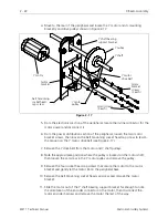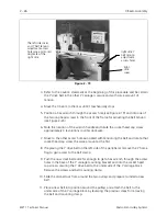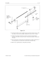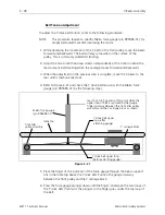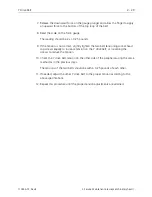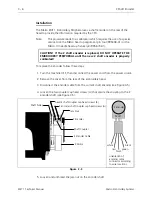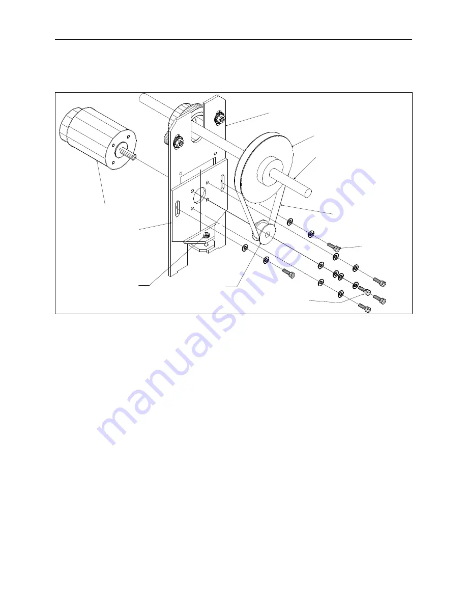
4. Move to the rear of the peripheral and locate the Y motor and its mounting
bracketry and drive pulleys shown in Figure 2-17.
5. From the electronics section of the peripheral, locate the in-line connector for the
motor power and disconnect it.
6. From the power distribution section of the peripheral, loosen the two motor
bracket screws, then loosen the belt tensioning socket head cap screw to lessen
the tension on the Y motor drive belt (see Figure 2-17).
7. Remove the Y drive belt from the motor and Y shaft pulleys.
8. Note the approximate position where the pulley is located on the motor shaft,
then loosen the set screw in the Y motor pulley and remove the pulley.
9. Remove the four socket head cap screws that secure the motor to the motor
bracket and gently let the motor lie on the peripheral base.
10. Remove the belt tensioning socket head cap screw and remove the motor
bracket.
11. Slide the motor out of the Y shaft bearing support bracket far enough to note
the orientation of the encoder connector on the motor, then disconnect the
motor encoder harness and remove the motor the rest of the way.
Y motor
drive belt
Y motor
Y shaft
Y motor
pulley
belt tensioning
socket head
cap screw
Y pulley
motor screws
(4 each)
motor
bracket
Y shaft bearing
support bracket
motor
bracket
screws
(2 each)
Figure 2 - 17
2 - 22
X Beam Assembly
EMT 1 Technical Manual
Melco Embroidery Systems
Содержание EMT 1
Страница 6: ...This page intentionally left blank Table of Contents 110344 01 Revision B iv EMT 1 Technical Manual ...
Страница 44: ...This page intentionally left blank 2 30 X Beam Assembly EMT 1 Technical Manual Melco Embroidery Systems ...
Страница 74: ...This page intentionally left blank 3 30 Rotary Hook EMT 1 Technical Manual Melco Embroidery Systems ...


