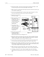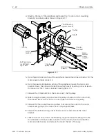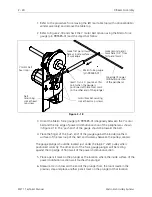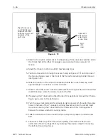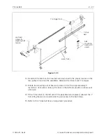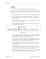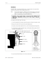
6. Grasp the force gauge body and push down on the gauge until the lower loop of
the belt just touches the X carriage rail.
7. Read the scale on the gauge while maintaining the situation in the previous step.
The reading should be between 3.5 and 4.0 pounds (3.75 +/- 0.25).
8. If the reading on the gauge is not within the specified range, repeat this belt
tension procedure until the reading is within the specified range.
Tighten the drive belt tensioning screw clockwise to increase the belt tension.
Loosen the drive belt tensioning screw counter clockwise to decrease the belt
tension.
9. Tighten the tensioner block mounting screws and replace the beam cover.
Lint Wiper
Located on the underneath side of the X drive belt tensioner block is a piece of
Velcro attached with adhesive. This item is used to keep the top surface of the X
carriage "brushed" clean and smooth for accurate reading by the X home sensor in
that area of the carriage. In the unlikely event this needs to be replaced, it must be
formed with a ripple in it to reach the X carriage surface but with some yielding of
position. To form this ripple, simply form the middle section of the piece of Velcro
around a 2mm (or equivalent) hex wrench as you attach it to the tensioner block.
When the Velcro is securely attached, twist the wrench out from between it and the
block. A rippled portion of the Velcro piece remains.
Y Motor
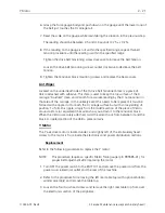
The Y axis drive motor is located under, and slightly left of, the embroidery head.
Access to the motor is from inside the electronics and power distribution sections.
Replacement
Refer to the following procedure to replace the Y motor:
NOTE:
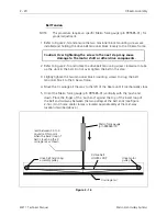
This procedure requires a specific Melco force gauge (p/n 995585-01), for
proper belt adjustment after replacing the motor.
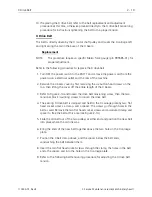
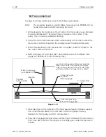
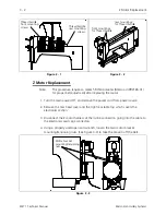
1. Turn OFF the power switch to the EMT 10T and remove the power cord from the
power source electrical outlet and the rear of the machine.
2. Refer to the procedure for removing the left rear table top (with optional bobbin
winder assembly) and remove the table top.
3. Loosen the four truss head screws and remove the right rear table top from over
the electronics section of the peripheral.
Y Motor
2 - 21
110344-01, Rev B
2. Service Maintenance (except embroidery head )
Содержание EMT 1
Страница 6: ...This page intentionally left blank Table of Contents 110344 01 Revision B iv EMT 1 Technical Manual ...
Страница 44: ...This page intentionally left blank 2 30 X Beam Assembly EMT 1 Technical Manual Melco Embroidery Systems ...
Страница 74: ...This page intentionally left blank 3 30 Rotary Hook EMT 1 Technical Manual Melco Embroidery Systems ...


