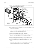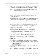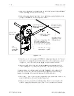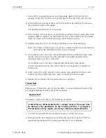
X Beam Assembly
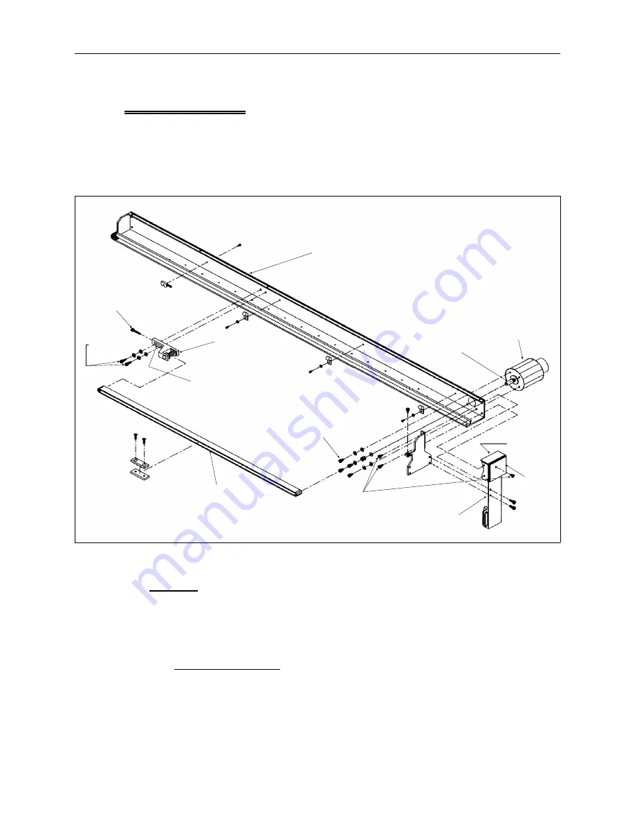
The X beam assembly consists of the X carriage, X motor, X drive belt, and various
other mechanical components that make up the device that holds the hoop during
the embroidery process. The X beam is attached to the Y drive system by
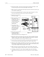
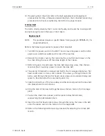
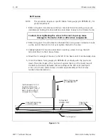
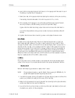
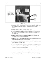
connecting to the Y drive rails at either end of the beam. Refer to Figure 2-14 to
identify various areas of the X beam assembly.
X Motor
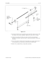
The X motor is attached to the back side of the right end of the X beam. The shaft
pulley is a direct connection to the X drive belt. Refer to the following procedure to
replace the X motor and adjust the X drive belt tension.
Motor Replacement
NOTE:
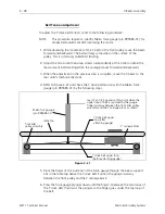
This procedure requires a specific Melco force gauge (p/n 995585-01) for
proper belt adjustment after replacing the motor.
1. Turn OFF the power switch to the EMT 1 and remove the power cord from the
power source electrical outlet and the rear of the machine.
drive belt
tensioning
screw
X beam
tensioner
block
mounting
screws
X drive belt
motor
pulley
motor screws
(4 each)
X motor
X harness
interface PCB
see detail
of this
area in
Figure 2-15
X harness
interface PCB
cover screws
(3 each)
cover
X carriage removed to
show X beam detail
Velcro lint wiper
located under
tensioner block
Figure 2 - 14
X Motor
2 - 17
110344-01, Rev B
2. Service Maintenance (except embroidery head )
Содержание EMT 1
Страница 6: ...This page intentionally left blank Table of Contents 110344 01 Revision B iv EMT 1 Technical Manual ...
Страница 44: ...This page intentionally left blank 2 30 X Beam Assembly EMT 1 Technical Manual Melco Embroidery Systems ...
Страница 74: ...This page intentionally left blank 3 30 Rotary Hook EMT 1 Technical Manual Melco Embroidery Systems ...


