8. Remove the PCB and cover together.
9. Install a static grounding strap between the working surface and the personnel
performing this procedure.
10. Remove the 4 screws that secure the keyboard/display assembly PCB to the
cover.
11. Disconnect the 3-button harness from the PCB.
12. Remove the keyboard/display assembly PCB from the keyboard cover.
13. Transfer the key caps from the old PCB to the new PCB by simply lifting them off
of the keys by using finger pressure only. It is recommended that this be done
one key at a time to avoid errors in key cap arrangement on the new PCB.
14. When the key caps are transferred, reinstall the keyboard/display assembly by
reversing the preceding steps.
NOTE:
When re-attaching the PCB to the cover, be certain the ground wire is
attached at the 4th screw and that when the screws are tightened the
buttons do not stick in the cover holes when pressed.
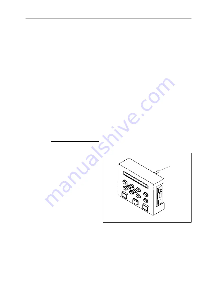
Display Screen Intensity
During the adjustment of the display intensity the EMT 1 must be turned on so the
result of the adjustment may
be observed.
1. Locate the intensity
adjustment knob on the
top, rear of the
keyboard/display printed
circuit board as shown in
Figure 2-2.
2. Turn ON the power switch
to the EMT 1.
3. When facing the machine
from the front, rotate the
adjustment potentiometer
clockwise to decrease
intensity on the display, or
counterclockwise to increase the intensity on the display.
intensity
adjustment
knob
Figure 2 - 2
Display Screen Intensity
2 - 3
110344-01, Rev B
2. Service Maintenance (except embroidery head )
Содержание EMT 1
Страница 6: ...This page intentionally left blank Table of Contents 110344 01 Revision B iv EMT 1 Technical Manual ...
Страница 44: ...This page intentionally left blank 2 30 X Beam Assembly EMT 1 Technical Manual Melco Embroidery Systems ...
Страница 74: ...This page intentionally left blank 3 30 Rotary Hook EMT 1 Technical Manual Melco Embroidery Systems ...


