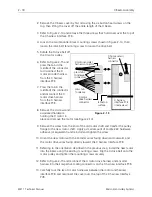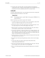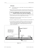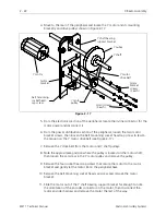
10. Push the module toward the rear allowing the loosened screws to capture the
module within the right angled portion of the slots.
11. Install remaining two screws in the base of the power distribution module and
four in the rear wall of the power distribution section. Tighten all eight screws.
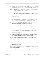
12. Reinstall the three harnesses in the top, the power switch harness at the side,
and the ground wire to the stud near the rear left corner of the power
distribution section.
NOTE: When a new power distribution module is installed, there is no
requirement for adjusting any voltages.
13. Reinstall the left rear table top (with optional bobbin winder assembly).
14. Reattach the power cord to the peripheral voltage source.
2 - 10
Power Distribution Section
EMT 1 Technical Manual
Melco Embroidery Systems
Содержание EMT 1
Страница 6: ...This page intentionally left blank Table of Contents 110344 01 Revision B iv EMT 1 Technical Manual ...
Страница 44: ...This page intentionally left blank 2 30 X Beam Assembly EMT 1 Technical Manual Melco Embroidery Systems ...
Страница 74: ...This page intentionally left blank 3 30 Rotary Hook EMT 1 Technical Manual Melco Embroidery Systems ...


