Belt Tension
NOTE:
This procedure requires a specific Melco force gauge (p/n 995585-01), for
proper adjustment.
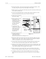
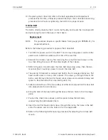
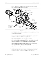
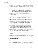
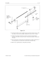
1. Refer to Figure 2-14 and ensure the two tensioner block mounting screws are
installed and holding the drive belt tensioner block loosely to the X beam frame.
Caution: Over tightening the screw in the next step may cause
damage to the motor shaft or other drive components.
2. Refer to Figure 2-14 and rotate the drive belt tensioning screw clockwise to take
up the slack in the belt. Do not over tighten the belt in this step.
3. Slightly tighten the two tensioner block mounting screws to snug the belt
tensioner block to the X beam frame.
4. Move the X carriage all the way to the left of the beam until it mechanically stops.
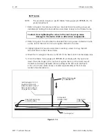
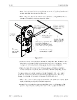
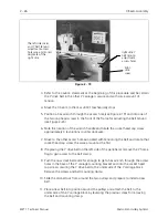
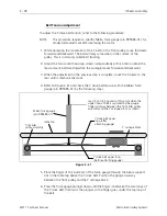
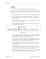
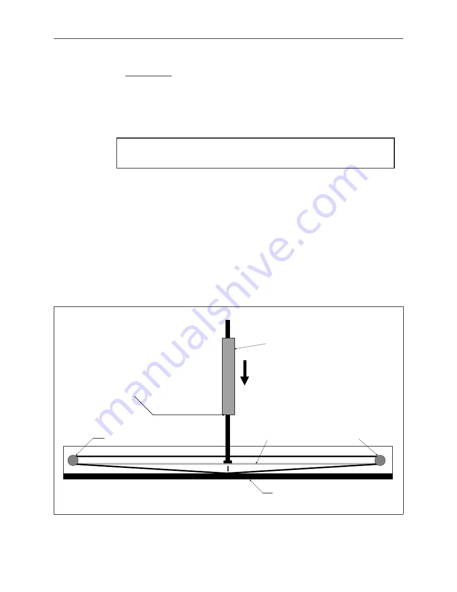
5. Orient the Melco force gauge (p/n 995585-01) vertically with the ’push end’
down. Place the finger of the ’push end’ against the top of the lower loop of
the belt and mid-way between the two pulleys at the belt ends (see Figure
2-16). (An X home cable clamps is located approximately at the mid-way
location described above.)
read between 3.5 to 4
pounds at this point
when the lower loop of
belt is touching the X
carriage rail as shown
Melco force gauge
(p/n 995585-01)
drive motor
pulley
X carriage rail
drive belt tensioning
assembly pulley
X drive belt
LOWER LOOP
Figure 2 - 16
2 - 20
X Beam Assembly
EMT 1 Technical Manual
Melco Embroidery Systems
Содержание EMT 1
Страница 6: ...This page intentionally left blank Table of Contents 110344 01 Revision B iv EMT 1 Technical Manual ...
Страница 44: ...This page intentionally left blank 2 30 X Beam Assembly EMT 1 Technical Manual Melco Embroidery Systems ...
Страница 74: ...This page intentionally left blank 3 30 Rotary Hook EMT 1 Technical Manual Melco Embroidery Systems ...


