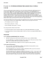
For RISLU using DFI with FE mode, the maximum number of ports per PSU shelf is 96. This number
includes all packet switch ports beside ACD/OSPS positions.
Identify time slots which are currently assigned to the RISLU by reviewing RC/V 22.19 where LU field
indicates the RISLU unit number to be converted.
The total number of fully assigned time slots for the RISLU (RC/V 22.19 ST field indicates F) must be
less than or equal to the number of empty (or unused) time slots (RC/V 22.19 ST field indicates N) on
the same PSU shelf. If the total number of fully assigned time slots is greater than the number of empty
time slots, then ONE port from each of the FULL time slots must be degrown or deleted until the number
of FULL time slots is equal to the number of empty time slots (by checking with RC/V 22.19 after each
port is deleted) prior to the conversion.
The previous action would greatly reduce the chance of failure when updating RC/V view 22.9 during the
RISLU conversion.
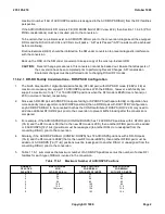
Table 11.6-2 summarizes the previous discussion.
Table 11.6-2 Summary of Reassignment of ACD/OSPS Positions
CURRENT
DFI
MODE
REQUIRED
NEW
DFI MODE
NUMBER
OF
FULL TS
NUMBER
OF
EMPTY TS
ACTION
REQUIRED
NUMBER
OF PORTS
AFFECTED
FE8Z
B8ZS
-
-
No
-
FE
ZCS
0
-
No
-
FE
ZCS
5
6
No
-
FE
ZCS
6
6
No
-
FE
ZCS
X
X
No
-
FE
ZCS
6
5
Yes
1
FE
ZCS
12
5
Yes
7
FE
ZCS
32 (Max)
0
Yes
32
NOTE:
At most, only ONE port belonging to each fully assigned time slot (time slot with ST field equals to F
for the PSU shelf in RC/V view 22.19) of the ACD/OSPS RISLU to be converted, will need to be
degrown per PSIUPIDB time slot.
The removed ports can be reinserted to the same RISLU after the conversion providing that there are
available empty or partially full time slots on the PSIUPIDB (by reading relation rlDGRP_RI again).
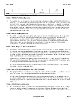
11.6.2.9 Post-Conversion
1.
If some ports were degrown prior to the conversion, the following steps may be used to reinsert the ports
after a successful conversion providing that the PSU time slot pool is not exhausted.
NOTE:
The reinsert work may include physical hardware movement of RISLU LCs to other positions.
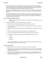
(A) Time Slot Available Verifications
Collect the "post-conversion" PSU time slots data using Section 11.65.2.2.3. The following restrictions
must be met before degrown ports can be re-inserted. If the data indicates otherwise, hardware
addition (PSU shelf or PH) may be needed to add more RISLU port.
For 5E9(1) and 5E9(2) software releases:
Verify that (PSIUPIDB.sh_ts_nailup - PSIUPIDB.rpa_ts) is less than 32.
235-105-210
October 1999
Copyright © 1999
Page 5
Содержание 5ESS-2000
Страница 96: ...235 105 210 October 1999 Copyright 1999 Page 2 ...
Страница 184: ...235 105 210 October 1999 Copyright 1999 Page 3 ...
Страница 300: ...13 STOP YOU HAVE COMPLETED THIS PROCEDURE 235 105 210 October 1999 Copyright 1999 Page 55 ...
Страница 339: ...7 STOP YOU HAVE COMPLETED THIS PROCEDURE 235 105 210 October 1999 Copyright 1999 Page 13 ...
Страница 342: ...235 105 210 October 1999 Copyright 1999 Page 2 ...
Страница 359: ...235 105 210 October 1999 Copyright 1999 Page 5 ...
Страница 516: ...Figure 10 24 1 KS 23483 L13 Disk Drive Cable Connection Rear View 235 105 210 October 1999 Copyright 1999 Page 2 ...
Страница 517: ...Figure 10 24 2 KS 23483 L21 Disk Drive Cable Connection Rear View 235 105 210 October 1999 Copyright 1999 Page 3 ...
Страница 518: ...Figure 10 24 3 KS 23841 L15 Disk Drive Cable Connection Rear View 235 105 210 October 1999 Copyright 1999 Page 4 ...
Страница 523: ...Figure 10 24 6 Top View of DUP Showing Internal Cabling 235 105 210 October 1999 Copyright 1999 Page 9 ...
Страница 609: ...2 STOP YOU HAVE COMPLETED THIS PROCEDURE 235 105 210 October 1999 Copyright 1999 Page 12 ...
Страница 628: ...a SM inhibited Response OK 2 STOP YOU HAVE COMPLETED THIS PROCEDURE 235 105 210 October 1999 Copyright 1999 Page 8 ...
Страница 653: ...Response OK 2 STOP YOU HAVE COMPLETED THIS PROCEDURE 235 105 210 October 1999 Copyright 1999 Page 16 ...
Страница 676: ...235 105 210 October 1999 Copyright 1999 Page 9 ...
Страница 792: ...3 STOP YOU HAVE COMPLETED THIS PROCEDURE 235 105 210 October 1999 Copyright 1999 Page 9 ...
Страница 799: ...Figure 11 36 3 1 Cleaning Points 235 105 210 October 1999 Copyright 1999 Page 7 ...
Страница 801: ...235 105 210 October 1999 Copyright 1999 Page 9 ...
Страница 839: ...2 STOP YOU HAVE COMPLETED THIS PROCEDURE 235 105 210 October 1999 Copyright 1999 Page 16 ...
Страница 999: ...2 STOP YOU HAVE COMPLETED THIS PROCEDURE 235 105 210 October 1999 Copyright 1999 Page 13 ...
Страница 1008: ...Figure 11 55 1 CTSNS DIP Switch Settings 235 105 210 October 1999 Copyright 1999 Page 2 ...
Страница 1011: ...235 105 210 October 1999 Copyright 1999 Page 5 ...
Страница 1053: ...235 105 210 October 1999 Copyright 1999 Page 15 ...
Страница 1165: ...Procedure 14 14 RESERVED FOR FUTURE USE PROCEDURE 1 Reserved For future use 235 105 210 October 1999 Copyright 1999 Page 1 ...
Страница 1186: ...Procedure 14 17 RESERVED FOR FUTURE USE PROCEDURE 1 Reserved For future use 235 105 210 October 1999 Copyright 1999 Page 1 ...
Страница 1187: ...Procedure 14 18 RESERVED FOR FUTURE USE PROCEDURE 1 Reserved For future use 235 105 210 October 1999 Copyright 1999 Page 1 ...
Страница 1284: ...Figure 15 15 1 PARADYNE Paradyne Corporation 3810 Modem Diagnostic Control Panel 235 105 210 October 1999 Copyright 1999 Page 6 ...
Страница 1287: ...Figure 15 16 1 153A Adapter Connection Figure 15 16 2 AMATPS Block Diagram 235 105 210 October 1999 Copyright 1999 Page 3 ...
Страница 1289: ...Figure 15 17 2 AMATPS Data Link 235 105 210 October 1999 Copyright 1999 Page 2 ...
Страница 1290: ...Figure 15 17 3 Single Housing B25A Cable Assembly 235 105 210 October 1999 Copyright 1999 Page 3 ...
Страница 1292: ...235 105 210 October 1999 Copyright 1999 Page 5 ...
Страница 1294: ...Figure 15 17 8 201C to TN82 Data Set Cable Drawing 235 105 210 October 1999 Copyright 1999 Page 7 ...
Страница 1303: ...9 STOP YOU HAVE COMPLETED THIS PROCEDURE 235 105 210 October 1999 Copyright 1999 Page 2 ...
Страница 1324: ...11 Type and enter q 12 STOP YOU HAVE COMPLETED THIS PROCEDURE 235 105 210 October 1999 Copyright 1999 Page 2 ...
Страница 1342: ...Figure 15 40 1 SCANS II Dial Up Data Set Installation Diagram 235 105 210 October 1999 Copyright 1999 Page 2 ...
Страница 1344: ...Figure 15 40 4 59A1 Mounting Front in Slot J3 Figure 15 40 5 2048A Data Set Front 235 105 210 October 1999 Copyright 1999 Page 4 ...
Страница 1345: ...Figure 15 40 6 Berg Connector Terminations and Layout 235 105 210 October 1999 Copyright 1999 Page 5 ...
Страница 1346: ...Figure 15 40 7 B25A Cable 4 STOP YOU HAVE COMPLETED THIS PROCEDURE 235 105 210 October 1999 Copyright 1999 Page 6 ...
Страница 1360: ...Figure 15 47 2 Typical SCANS III Link Diagram 235 105 210 October 1999 Copyright 1999 Page 2 ...
Страница 1368: ...Response FA or OK appears 17 STOP YOU HAVE COMPLETED THIS PROCEDURE 235 105 210 October 1999 Copyright 1999 Page 2 ...
Страница 1372: ...235 105 210 October 1999 Copyright 1999 Page 2 ...
Страница 1374: ...235 105 210 October 1999 Copyright 1999 Page 4 ...
Страница 1376: ...Figure 15 55 6 201C to TN83 Data Set Cable Drawing 235 105 210 October 1999 Copyright 1999 Page 6 ...
Страница 1418: ...Figure 15 56 1 PARADYNE 3810 Modem Diagnostic Control Panel 235 105 210 October 1999 Copyright 1999 Page 4 ...
Страница 1421: ...Table 1 1 O M Checklist 235 105 210 October 1999 Copyright 1999 Page 3 ...

