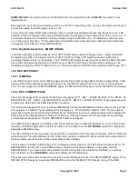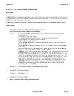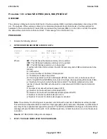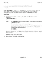
Procedure 13.1: INITIATE REX SCHEDULING
OVERVIEW
The
EXC:REX
input message executes either one or all valid test types of routine exercise (REX) of the hardware in
the communication module (CM), and all switching modules (SMs) or in the CM, or in a range of SMs. The demand
mode or the verbose mode can be specified.
Caution: The
EXC:REX
message may result in severe traffic interruption if the DEMAND option is used.
PROCEDURE
1.
At the master control center (MCC) video terminal, type and enter:
EXC:REX[,CM][,SM=a&&b][,c][,VERBOSE][,DEMAND];
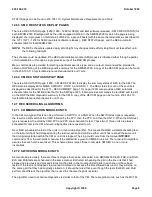
Where:
a
= Number of the SM on which REX is to start running or the lower limit of a range of
module numbers
b
= Upper limit on a range of SMs
c
= REX test type to be executed (default is to execute all three test types)
=
DGN - Execute the summary of diagnostic tests
DGN on CM can take some time.
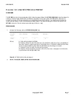
=
ELS - Execute the summary of electronic loop segregation tests (This is not a valid test
type for the CM.)
=
FAB - Execute the summary of fabric exerciser tests of grids (This is not a valid test type
for the CM.)
=
SWITCH - Switch of the CM hardware states only (If neither CM nor SM is specified the
hardware is tested in the CM and all of the operational SMs.)
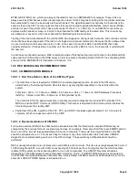
DEMAND
= Start the REX in the demand mode. Default is the nondemand mode. Do not use
the DEMAND option if the SM is cut-over and taking live traffic, as this results in severe
traffic interruption. The DEMAND option is specified only when the SM is in the pre-cut state
(that is, not in operation and taking no live traffic.) This mode is provided to test the circuits
that are not tested in normal mode because, when they are taken out of service for test, the
subtending trunks are also taken out of service. The demand-only phases of the circuit
diagnostics are also run during this mode. The demand option is not allowed for the CM.
VERBOSE
= Print each unit completion message on the ROP and on the terminal that
requested it. (Default is not to print the completion message for each unit but still print
failures for each unit on the ROP.)
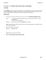
Response:
PF
is printed followed by the
EXC REX
output message.
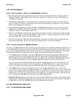
2.
Analyze EXC REX output message.
Reference:
Procedure 13.2
Results:
REX scheduling initiated.
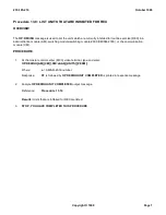
3.
STOP. YOU HAVE COMPLETED THIS PROCEDURE.
235-105-210
October 1999
Copyright © 1999
Page 1
Содержание 5ESS-2000
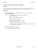
Страница 96: ...235 105 210 October 1999 Copyright 1999 Page 2 ...
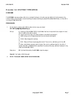
Страница 184: ...235 105 210 October 1999 Copyright 1999 Page 3 ...
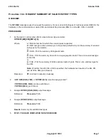
Страница 300: ...13 STOP YOU HAVE COMPLETED THIS PROCEDURE 235 105 210 October 1999 Copyright 1999 Page 55 ...
Страница 339: ...7 STOP YOU HAVE COMPLETED THIS PROCEDURE 235 105 210 October 1999 Copyright 1999 Page 13 ...
Страница 342: ...235 105 210 October 1999 Copyright 1999 Page 2 ...
Страница 359: ...235 105 210 October 1999 Copyright 1999 Page 5 ...
Страница 516: ...Figure 10 24 1 KS 23483 L13 Disk Drive Cable Connection Rear View 235 105 210 October 1999 Copyright 1999 Page 2 ...
Страница 517: ...Figure 10 24 2 KS 23483 L21 Disk Drive Cable Connection Rear View 235 105 210 October 1999 Copyright 1999 Page 3 ...
Страница 518: ...Figure 10 24 3 KS 23841 L15 Disk Drive Cable Connection Rear View 235 105 210 October 1999 Copyright 1999 Page 4 ...
Страница 523: ...Figure 10 24 6 Top View of DUP Showing Internal Cabling 235 105 210 October 1999 Copyright 1999 Page 9 ...
Страница 609: ...2 STOP YOU HAVE COMPLETED THIS PROCEDURE 235 105 210 October 1999 Copyright 1999 Page 12 ...
Страница 628: ...a SM inhibited Response OK 2 STOP YOU HAVE COMPLETED THIS PROCEDURE 235 105 210 October 1999 Copyright 1999 Page 8 ...
Страница 653: ...Response OK 2 STOP YOU HAVE COMPLETED THIS PROCEDURE 235 105 210 October 1999 Copyright 1999 Page 16 ...
Страница 676: ...235 105 210 October 1999 Copyright 1999 Page 9 ...
Страница 792: ...3 STOP YOU HAVE COMPLETED THIS PROCEDURE 235 105 210 October 1999 Copyright 1999 Page 9 ...
Страница 799: ...Figure 11 36 3 1 Cleaning Points 235 105 210 October 1999 Copyright 1999 Page 7 ...
Страница 801: ...235 105 210 October 1999 Copyright 1999 Page 9 ...
Страница 839: ...2 STOP YOU HAVE COMPLETED THIS PROCEDURE 235 105 210 October 1999 Copyright 1999 Page 16 ...
Страница 999: ...2 STOP YOU HAVE COMPLETED THIS PROCEDURE 235 105 210 October 1999 Copyright 1999 Page 13 ...
Страница 1008: ...Figure 11 55 1 CTSNS DIP Switch Settings 235 105 210 October 1999 Copyright 1999 Page 2 ...
Страница 1011: ...235 105 210 October 1999 Copyright 1999 Page 5 ...
Страница 1053: ...235 105 210 October 1999 Copyright 1999 Page 15 ...
Страница 1165: ...Procedure 14 14 RESERVED FOR FUTURE USE PROCEDURE 1 Reserved For future use 235 105 210 October 1999 Copyright 1999 Page 1 ...
Страница 1186: ...Procedure 14 17 RESERVED FOR FUTURE USE PROCEDURE 1 Reserved For future use 235 105 210 October 1999 Copyright 1999 Page 1 ...
Страница 1187: ...Procedure 14 18 RESERVED FOR FUTURE USE PROCEDURE 1 Reserved For future use 235 105 210 October 1999 Copyright 1999 Page 1 ...
Страница 1284: ...Figure 15 15 1 PARADYNE Paradyne Corporation 3810 Modem Diagnostic Control Panel 235 105 210 October 1999 Copyright 1999 Page 6 ...
Страница 1287: ...Figure 15 16 1 153A Adapter Connection Figure 15 16 2 AMATPS Block Diagram 235 105 210 October 1999 Copyright 1999 Page 3 ...
Страница 1289: ...Figure 15 17 2 AMATPS Data Link 235 105 210 October 1999 Copyright 1999 Page 2 ...
Страница 1290: ...Figure 15 17 3 Single Housing B25A Cable Assembly 235 105 210 October 1999 Copyright 1999 Page 3 ...
Страница 1292: ...235 105 210 October 1999 Copyright 1999 Page 5 ...
Страница 1294: ...Figure 15 17 8 201C to TN82 Data Set Cable Drawing 235 105 210 October 1999 Copyright 1999 Page 7 ...
Страница 1303: ...9 STOP YOU HAVE COMPLETED THIS PROCEDURE 235 105 210 October 1999 Copyright 1999 Page 2 ...
Страница 1324: ...11 Type and enter q 12 STOP YOU HAVE COMPLETED THIS PROCEDURE 235 105 210 October 1999 Copyright 1999 Page 2 ...
Страница 1342: ...Figure 15 40 1 SCANS II Dial Up Data Set Installation Diagram 235 105 210 October 1999 Copyright 1999 Page 2 ...
Страница 1344: ...Figure 15 40 4 59A1 Mounting Front in Slot J3 Figure 15 40 5 2048A Data Set Front 235 105 210 October 1999 Copyright 1999 Page 4 ...
Страница 1345: ...Figure 15 40 6 Berg Connector Terminations and Layout 235 105 210 October 1999 Copyright 1999 Page 5 ...
Страница 1346: ...Figure 15 40 7 B25A Cable 4 STOP YOU HAVE COMPLETED THIS PROCEDURE 235 105 210 October 1999 Copyright 1999 Page 6 ...
Страница 1360: ...Figure 15 47 2 Typical SCANS III Link Diagram 235 105 210 October 1999 Copyright 1999 Page 2 ...
Страница 1368: ...Response FA or OK appears 17 STOP YOU HAVE COMPLETED THIS PROCEDURE 235 105 210 October 1999 Copyright 1999 Page 2 ...
Страница 1372: ...235 105 210 October 1999 Copyright 1999 Page 2 ...
Страница 1374: ...235 105 210 October 1999 Copyright 1999 Page 4 ...
Страница 1376: ...Figure 15 55 6 201C to TN83 Data Set Cable Drawing 235 105 210 October 1999 Copyright 1999 Page 6 ...
Страница 1418: ...Figure 15 56 1 PARADYNE 3810 Modem Diagnostic Control Panel 235 105 210 October 1999 Copyright 1999 Page 4 ...
Страница 1421: ...Table 1 1 O M Checklist 235 105 210 October 1999 Copyright 1999 Page 3 ...

