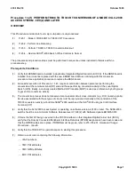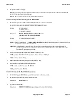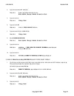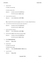
Procedure 11.45: PERFORM TR008 TO TR303 RT CONVERSION OF A MODE II
SLC
-2000
ACCESS SYSTEM - 5E9(2) AND LATER
OVERVIEW
This Procedure is divided into four major sub-parts or sub-procedures:
(1)
11.45.1 - Mode II TR008 VRT to TR303 VRT Conversion
(2)
11.45.2 - Perform Line Rehoming
(3)
11.45.3 - Perform TR008 to TR303 Conversion Backout
(4)
11.45.4 - Restore
5ESS
®
-2000 Switch Office Controls to Normal.
The procedures and procedure steps must be performed in sequence unless instructed otherwise within a
procedure step.
Prerequisite Conditions
(1)
Verify that KBN6B board is installed in applicable Integrated Digital Carrier Unit (IDCU). If the KBN6 board is
installed then it must be replaced with the new KBN6B board before continuing with this conversion
procedure. Use applicable procedure to replace the KBN6 board.
(2)
Successful execution of Procedure 11.45 requires coordination between personnel performing the
conversion at the remote terminal (RT) site and those performing conversion activity at the Local Digital
Switch (LDS). Ideally, a mutually created Method Of Procedure (MOP) is used as a reference by both groups
to govern the conversion activity.
(3)
The conversion process does not preserve data on special circuit cross-connects (e.g., DID, nailed-up ports).
Service associated with these types of circuits must be reprovisioned manually at the conclusion of the
TR303 conversion activity, at both the
5ESS
®
-2000 switch and the
SLC
®
-2000 using its Craft Interface
Terminal (CIT).
(4)
Verify that the SLC-2000 Access System is operating on software version 4.01.00 or later. The 5ESS-2000
switch should be on a minimum Software Release level of 5E9(2) with Software Update BWM95-0018.
(5)
If this is the first RT being converted to the TR303 interface on this Integrated Digital Carrier Unit (IDCU),
verify that the Directly Connected Peripheral Interface Data Bus (DPIDB) assignments have been made and
that the DPIDB cables are in place. If DPIBDs must be grown, refer to 235-105-231,
Hardware Change
Procedures - Growth
.
(6)
Verify that the TR008 RT is operational prior to starting this procedure.
(7)
Obtain a work order containing the following information:
IFAC numbers
TMC PRI attributes
TMC NPRI attributes
EOC PRI attributes
235-105-210
October 1999
Copyright © 1999
Page 1
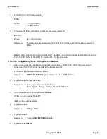
Содержание 5ESS-2000
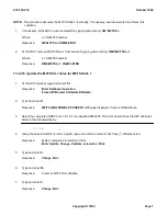
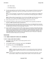
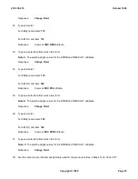
Страница 96: ...235 105 210 October 1999 Copyright 1999 Page 2 ...
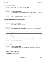
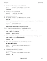
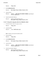
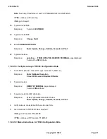
Страница 184: ...235 105 210 October 1999 Copyright 1999 Page 3 ...
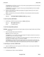
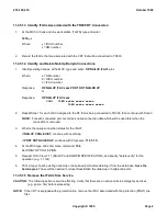
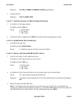
Страница 300: ...13 STOP YOU HAVE COMPLETED THIS PROCEDURE 235 105 210 October 1999 Copyright 1999 Page 55 ...
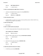
Страница 339: ...7 STOP YOU HAVE COMPLETED THIS PROCEDURE 235 105 210 October 1999 Copyright 1999 Page 13 ...
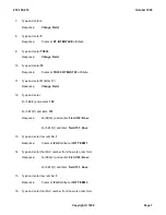
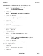
Страница 342: ...235 105 210 October 1999 Copyright 1999 Page 2 ...
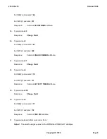
Страница 359: ...235 105 210 October 1999 Copyright 1999 Page 5 ...
Страница 516: ...Figure 10 24 1 KS 23483 L13 Disk Drive Cable Connection Rear View 235 105 210 October 1999 Copyright 1999 Page 2 ...
Страница 517: ...Figure 10 24 2 KS 23483 L21 Disk Drive Cable Connection Rear View 235 105 210 October 1999 Copyright 1999 Page 3 ...
Страница 518: ...Figure 10 24 3 KS 23841 L15 Disk Drive Cable Connection Rear View 235 105 210 October 1999 Copyright 1999 Page 4 ...
Страница 523: ...Figure 10 24 6 Top View of DUP Showing Internal Cabling 235 105 210 October 1999 Copyright 1999 Page 9 ...
Страница 609: ...2 STOP YOU HAVE COMPLETED THIS PROCEDURE 235 105 210 October 1999 Copyright 1999 Page 12 ...
Страница 628: ...a SM inhibited Response OK 2 STOP YOU HAVE COMPLETED THIS PROCEDURE 235 105 210 October 1999 Copyright 1999 Page 8 ...
Страница 653: ...Response OK 2 STOP YOU HAVE COMPLETED THIS PROCEDURE 235 105 210 October 1999 Copyright 1999 Page 16 ...
Страница 676: ...235 105 210 October 1999 Copyright 1999 Page 9 ...
Страница 792: ...3 STOP YOU HAVE COMPLETED THIS PROCEDURE 235 105 210 October 1999 Copyright 1999 Page 9 ...
Страница 799: ...Figure 11 36 3 1 Cleaning Points 235 105 210 October 1999 Copyright 1999 Page 7 ...
Страница 801: ...235 105 210 October 1999 Copyright 1999 Page 9 ...
Страница 839: ...2 STOP YOU HAVE COMPLETED THIS PROCEDURE 235 105 210 October 1999 Copyright 1999 Page 16 ...
Страница 999: ...2 STOP YOU HAVE COMPLETED THIS PROCEDURE 235 105 210 October 1999 Copyright 1999 Page 13 ...
Страница 1008: ...Figure 11 55 1 CTSNS DIP Switch Settings 235 105 210 October 1999 Copyright 1999 Page 2 ...
Страница 1011: ...235 105 210 October 1999 Copyright 1999 Page 5 ...
Страница 1053: ...235 105 210 October 1999 Copyright 1999 Page 15 ...
Страница 1165: ...Procedure 14 14 RESERVED FOR FUTURE USE PROCEDURE 1 Reserved For future use 235 105 210 October 1999 Copyright 1999 Page 1 ...
Страница 1186: ...Procedure 14 17 RESERVED FOR FUTURE USE PROCEDURE 1 Reserved For future use 235 105 210 October 1999 Copyright 1999 Page 1 ...
Страница 1187: ...Procedure 14 18 RESERVED FOR FUTURE USE PROCEDURE 1 Reserved For future use 235 105 210 October 1999 Copyright 1999 Page 1 ...
Страница 1284: ...Figure 15 15 1 PARADYNE Paradyne Corporation 3810 Modem Diagnostic Control Panel 235 105 210 October 1999 Copyright 1999 Page 6 ...
Страница 1287: ...Figure 15 16 1 153A Adapter Connection Figure 15 16 2 AMATPS Block Diagram 235 105 210 October 1999 Copyright 1999 Page 3 ...
Страница 1289: ...Figure 15 17 2 AMATPS Data Link 235 105 210 October 1999 Copyright 1999 Page 2 ...
Страница 1290: ...Figure 15 17 3 Single Housing B25A Cable Assembly 235 105 210 October 1999 Copyright 1999 Page 3 ...
Страница 1292: ...235 105 210 October 1999 Copyright 1999 Page 5 ...
Страница 1294: ...Figure 15 17 8 201C to TN82 Data Set Cable Drawing 235 105 210 October 1999 Copyright 1999 Page 7 ...
Страница 1303: ...9 STOP YOU HAVE COMPLETED THIS PROCEDURE 235 105 210 October 1999 Copyright 1999 Page 2 ...
Страница 1324: ...11 Type and enter q 12 STOP YOU HAVE COMPLETED THIS PROCEDURE 235 105 210 October 1999 Copyright 1999 Page 2 ...
Страница 1342: ...Figure 15 40 1 SCANS II Dial Up Data Set Installation Diagram 235 105 210 October 1999 Copyright 1999 Page 2 ...
Страница 1344: ...Figure 15 40 4 59A1 Mounting Front in Slot J3 Figure 15 40 5 2048A Data Set Front 235 105 210 October 1999 Copyright 1999 Page 4 ...
Страница 1345: ...Figure 15 40 6 Berg Connector Terminations and Layout 235 105 210 October 1999 Copyright 1999 Page 5 ...
Страница 1346: ...Figure 15 40 7 B25A Cable 4 STOP YOU HAVE COMPLETED THIS PROCEDURE 235 105 210 October 1999 Copyright 1999 Page 6 ...
Страница 1360: ...Figure 15 47 2 Typical SCANS III Link Diagram 235 105 210 October 1999 Copyright 1999 Page 2 ...
Страница 1368: ...Response FA or OK appears 17 STOP YOU HAVE COMPLETED THIS PROCEDURE 235 105 210 October 1999 Copyright 1999 Page 2 ...
Страница 1372: ...235 105 210 October 1999 Copyright 1999 Page 2 ...
Страница 1374: ...235 105 210 October 1999 Copyright 1999 Page 4 ...
Страница 1376: ...Figure 15 55 6 201C to TN83 Data Set Cable Drawing 235 105 210 October 1999 Copyright 1999 Page 6 ...
Страница 1418: ...Figure 15 56 1 PARADYNE 3810 Modem Diagnostic Control Panel 235 105 210 October 1999 Copyright 1999 Page 4 ...
Страница 1421: ...Table 1 1 O M Checklist 235 105 210 October 1999 Copyright 1999 Page 3 ...


