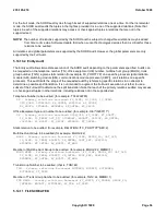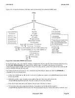
9257d012.94u The unofficial data file is created when the "UNOFC" parameter is used in the input message.
This data file is only accessible by the Customer PCs.
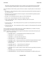
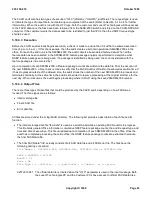
9257d012.94d The detail data file is created when the "DETAIL" parameter is used in the "EXC:FACR" input
message. The audit runs in the unofficial mode and provides a detailed report that shows how
a particular package count was incremented. (Refer to Section 5.16.3.5 for further
information).
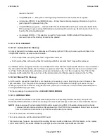
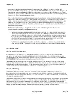
9257d012.94e The error file contains information in the event a fatal error is encountered during audit
execution. Otherwise this file is normally empty. The contents of this file inform the PC user
that a fatal error was encountered and that further action is required. Since the contents of the
FACR data file are questionable in this case, a FACR report will NOT be generated. Instead
the contents of the error file will be displayed to the PC user. A corresponding message is
output to the ROP to alert the maintenance technician to the error condition.
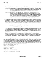
The error data file contains information pertaining to any data base read failures that were encountered during
the execution of the audit. This data is stored in ASCII text format to assist in fault analysis. All errors which are
recorded in this file indicate that a problem was encountered while the FACR audit was reading a relation in the
data base, and that further analysis may be required. The following is a sample of an error message stored in
this file:
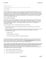
NON-FATAL ERROR: Failure to READ RTDNMOD/isatrtu()
RELATION KEYS: noc = 3, d4d3 = 1234
FC_LINE KEYS: member = 0xb1aa, module = 8, party = 0
( mod = 194 rc = -101 )
The first line in the error message indicates the relation trying to be read and what FACR software function the
error was encountered in. The second line provides the key(s) used when trying to read the relation. The third
line indicates what switch port the FACR audit was processing when the error occurred. The fourth line provides
the number of the switching module on which the read of the relation failed, and the return code from the failed
read request.
If and when a data base read error is encountered for a line or a trunk, the error is recorded and program
execution continues with the next port in the current SM/SM-2000 being processed. The error output is placed
in one of three files, either "facr.err1", "facr.err2" or "facr.err3". The error files are used in a cyclical fashion.
5.16.3.5 Detail Report
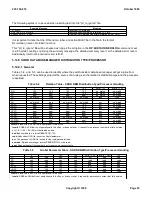
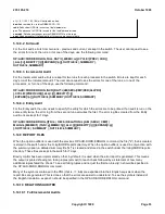
The FACR audit has the capability to create a detail report for a single NSEP package. This report is used to assist
in identifying which entities were found to have a feature activated which caused the NSEP package count to be
incremented. An entity may consist of either a line, trunk group or trunk, equipment port, or multiline hunt group. The
detail report contains a header that identifies the office, the date the report was created, the NSEP reported on, the
entity and a single feature that caused the NSEP package to be counted.
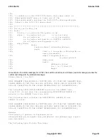
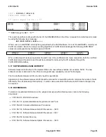
The following is a sample of a detail report :
DETAIL FACR NSEP REPORT
-----------------------
Office Name : NSC4
Office Base & Control :
nsc4d2
5ESS Software Release :
5E9(1)
Date of Detail Report Run :
07/10/94
NSEP =
ISDN1
235-105-210
October 1999
Copyright © 1999
Page 64
Содержание 5ESS-2000
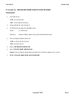
Страница 96: ...235 105 210 October 1999 Copyright 1999 Page 2 ...
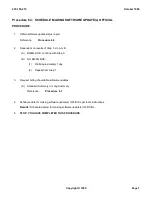
Страница 184: ...235 105 210 October 1999 Copyright 1999 Page 3 ...
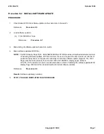
Страница 300: ...13 STOP YOU HAVE COMPLETED THIS PROCEDURE 235 105 210 October 1999 Copyright 1999 Page 55 ...
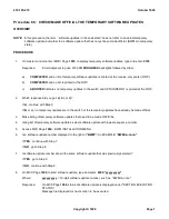
Страница 339: ...7 STOP YOU HAVE COMPLETED THIS PROCEDURE 235 105 210 October 1999 Copyright 1999 Page 13 ...
Страница 342: ...235 105 210 October 1999 Copyright 1999 Page 2 ...
Страница 359: ...235 105 210 October 1999 Copyright 1999 Page 5 ...
Страница 516: ...Figure 10 24 1 KS 23483 L13 Disk Drive Cable Connection Rear View 235 105 210 October 1999 Copyright 1999 Page 2 ...
Страница 517: ...Figure 10 24 2 KS 23483 L21 Disk Drive Cable Connection Rear View 235 105 210 October 1999 Copyright 1999 Page 3 ...
Страница 518: ...Figure 10 24 3 KS 23841 L15 Disk Drive Cable Connection Rear View 235 105 210 October 1999 Copyright 1999 Page 4 ...
Страница 523: ...Figure 10 24 6 Top View of DUP Showing Internal Cabling 235 105 210 October 1999 Copyright 1999 Page 9 ...
Страница 609: ...2 STOP YOU HAVE COMPLETED THIS PROCEDURE 235 105 210 October 1999 Copyright 1999 Page 12 ...
Страница 628: ...a SM inhibited Response OK 2 STOP YOU HAVE COMPLETED THIS PROCEDURE 235 105 210 October 1999 Copyright 1999 Page 8 ...
Страница 653: ...Response OK 2 STOP YOU HAVE COMPLETED THIS PROCEDURE 235 105 210 October 1999 Copyright 1999 Page 16 ...
Страница 676: ...235 105 210 October 1999 Copyright 1999 Page 9 ...
Страница 792: ...3 STOP YOU HAVE COMPLETED THIS PROCEDURE 235 105 210 October 1999 Copyright 1999 Page 9 ...
Страница 799: ...Figure 11 36 3 1 Cleaning Points 235 105 210 October 1999 Copyright 1999 Page 7 ...
Страница 801: ...235 105 210 October 1999 Copyright 1999 Page 9 ...
Страница 839: ...2 STOP YOU HAVE COMPLETED THIS PROCEDURE 235 105 210 October 1999 Copyright 1999 Page 16 ...
Страница 999: ...2 STOP YOU HAVE COMPLETED THIS PROCEDURE 235 105 210 October 1999 Copyright 1999 Page 13 ...
Страница 1008: ...Figure 11 55 1 CTSNS DIP Switch Settings 235 105 210 October 1999 Copyright 1999 Page 2 ...
Страница 1011: ...235 105 210 October 1999 Copyright 1999 Page 5 ...
Страница 1053: ...235 105 210 October 1999 Copyright 1999 Page 15 ...
Страница 1165: ...Procedure 14 14 RESERVED FOR FUTURE USE PROCEDURE 1 Reserved For future use 235 105 210 October 1999 Copyright 1999 Page 1 ...
Страница 1186: ...Procedure 14 17 RESERVED FOR FUTURE USE PROCEDURE 1 Reserved For future use 235 105 210 October 1999 Copyright 1999 Page 1 ...
Страница 1187: ...Procedure 14 18 RESERVED FOR FUTURE USE PROCEDURE 1 Reserved For future use 235 105 210 October 1999 Copyright 1999 Page 1 ...
Страница 1284: ...Figure 15 15 1 PARADYNE Paradyne Corporation 3810 Modem Diagnostic Control Panel 235 105 210 October 1999 Copyright 1999 Page 6 ...
Страница 1287: ...Figure 15 16 1 153A Adapter Connection Figure 15 16 2 AMATPS Block Diagram 235 105 210 October 1999 Copyright 1999 Page 3 ...
Страница 1289: ...Figure 15 17 2 AMATPS Data Link 235 105 210 October 1999 Copyright 1999 Page 2 ...
Страница 1290: ...Figure 15 17 3 Single Housing B25A Cable Assembly 235 105 210 October 1999 Copyright 1999 Page 3 ...
Страница 1292: ...235 105 210 October 1999 Copyright 1999 Page 5 ...
Страница 1294: ...Figure 15 17 8 201C to TN82 Data Set Cable Drawing 235 105 210 October 1999 Copyright 1999 Page 7 ...
Страница 1303: ...9 STOP YOU HAVE COMPLETED THIS PROCEDURE 235 105 210 October 1999 Copyright 1999 Page 2 ...
Страница 1324: ...11 Type and enter q 12 STOP YOU HAVE COMPLETED THIS PROCEDURE 235 105 210 October 1999 Copyright 1999 Page 2 ...
Страница 1342: ...Figure 15 40 1 SCANS II Dial Up Data Set Installation Diagram 235 105 210 October 1999 Copyright 1999 Page 2 ...
Страница 1344: ...Figure 15 40 4 59A1 Mounting Front in Slot J3 Figure 15 40 5 2048A Data Set Front 235 105 210 October 1999 Copyright 1999 Page 4 ...
Страница 1345: ...Figure 15 40 6 Berg Connector Terminations and Layout 235 105 210 October 1999 Copyright 1999 Page 5 ...
Страница 1346: ...Figure 15 40 7 B25A Cable 4 STOP YOU HAVE COMPLETED THIS PROCEDURE 235 105 210 October 1999 Copyright 1999 Page 6 ...
Страница 1360: ...Figure 15 47 2 Typical SCANS III Link Diagram 235 105 210 October 1999 Copyright 1999 Page 2 ...
Страница 1368: ...Response FA or OK appears 17 STOP YOU HAVE COMPLETED THIS PROCEDURE 235 105 210 October 1999 Copyright 1999 Page 2 ...
Страница 1372: ...235 105 210 October 1999 Copyright 1999 Page 2 ...
Страница 1374: ...235 105 210 October 1999 Copyright 1999 Page 4 ...
Страница 1376: ...Figure 15 55 6 201C to TN83 Data Set Cable Drawing 235 105 210 October 1999 Copyright 1999 Page 6 ...
Страница 1418: ...Figure 15 56 1 PARADYNE 3810 Modem Diagnostic Control Panel 235 105 210 October 1999 Copyright 1999 Page 4 ...
Страница 1421: ...Table 1 1 O M Checklist 235 105 210 October 1999 Copyright 1999 Page 3 ...

