background image

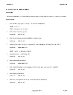
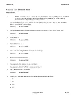
Procedure 15.7:  BRING UP SES II

PROCEDURE


1.

  NOTE:  

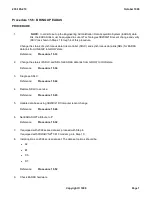
In order to set up the Service Evaluation System II (SES II) data link, the SES II link must

be equipped in Lucent Technologies 3B20D/21D Computer recent change and verify (RC/V) as
shown in Steps 1 through 4 of this procedure.

Change the status of synchronous data link controller (SDLC) and synchronous data link (SDL) for SES II
data link from UNEQIP to GROW state.

Reference: 

Procedure  15.38

2.

Change the status of SDLC and SDL for SES II data link from GROW to OOS state.

Reference: 

Procedure  15.39

3.

Diagnose SDLC.

Reference: 

Procedure  15.44

4.

Restore SDLC to service.

Reference: 

Procedure  15.45

5.

Update data base using 3B20D/21D Computer recent change.

Reference: 

Procedure  15.46

6.

Update SES attribute for trunk group number.

Reference: 

Procedure  15.35

7.

If equipped with 2024 series data set, proceed with Step 8.  
If equipped with 

PARADYNE

®

 3810 modem, go to Step 10.

8.

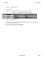
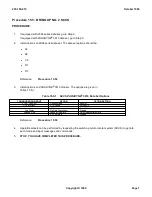
Install options on 2024 series data set. The data set options should be:

A2

B2

C5

D1

D7.

Reference: 

Procedure  15.52

235-105-210

October 1999

Copyright © 1999

Page 1

Содержание 5ESS-2000

Страница 1: ... 2000 Switch ROUTINE OPERATIONS AND MAINTENANCE PROCEDURES 5E11 1 and Later Software Releases Document 235 105 210 Issue Date October 1999 Issue Number 15 00A 235 105 210 October 1999 Copyright 1999 Page 1 ...

Страница 2: ...differ from any configuration currently installed Lucent Technologies is the successor to the business and assets of AT T Network Systems business unit Mandatory Customer Information Interference Information Part 15 of FCC Rules Refer to the 5ESS 2000 Switch Product Specification IP Trademarks 5ESS 2000 AUTOPLEX and SLC are registered trademarks of Lucent Technologies All other trademarks are iden...

Страница 3: ... assistance call the Customer Technical Assistance Management CTAM Center 1 800 225 4672 From inside the continental United States 1 630 224 4672 From outside the continental United States The CTAM center is staffed 24 hours a day 7 days a week Acknowledgment Developed by Lucent Technologies Customer Training and Information Products 235 105 210 October 1999 Copyright 1999 Page 2 ...

Страница 4: ...ncurrently from all documentation If you are supporting offices using a software release prior to 5E12 and have a need for the information that is being removed it is recommended that you retain the associated pages as they are removed from the paper documents or the earlier copy of CDROM 1 4 NAME CHANGE As of March 18 1999 Bellcore officially changed its name to Telcordia Technologies Not all pag...

Страница 5: ...CTION 9 MOVING HEAD DISK PROCEDURE DESCRIPTION This section contains descriptions for converting connecting or replacing moving head disks MHD SECTION 10 MOVING HEAD DISK PROCEDURES This section contains detailed level procedures for the subjects described in Section 9 of this manual NOTE Refer to 235 105 220 for Call Trace Procedures These procedures are not covered in 235 105 210 SECTION 11 MISC...

Страница 6: ...the Lucent Technologies Customer Information Center CIC in Indianapolis Indiana Most operating telephone companies should place orders through their documentation coordinator Some companies may allow customers to order directly from the Customer Information Center however the majority do not Companies that use documentation coordinators to manage their orders receive a significant discount If you ...

Страница 7: ...User s Guide 235 120 110 Very Compact Digital Exchange VCDX Reference Guide 235 120 120 Very Compact Digital Exchange VCDX User s Guide When appropriate this document contains references to the applicable CDX or VCDX documents Documents for the SEAGATE TECHNOLOGYTM CDC 340 megabyte MB SMD Disk drives may be obtained from Seagate Technology P O Box 12313 Room OK A 100 Oklahoma City OK 73157 TEL 405...

Страница 8: ... 9914V User Diagnostic Manual MG8015A 9914V Product Specification Manual Documents for the Laser Magnetic Storage International Company PERTEC interface 9 track tape units KEYSTONE II KS 22762 and KEYSTONE III KS 23113 can be ordered from Valley Forge Peripherals Inc 422 Business Center Building 0 1530 Oaks PA 19456 0908 TEL 610 666 3332 and are as follows 49762900 Reference Manual Model 92185 497...

Страница 9: ...nd Assistance Video Display Terminal Description and Operation 250 600 501 OSPS Automated Position Administration Reporting Recent Change and Software Maintenance for CSG 250 600 502J1 OSPS Automated Position Equipment Maintenance Job Aid 250 600 504 OSPS Automated Position VRCP Application for CSG 250 600 505 OSPS Automated Position SDAP Application for CSG 250 600 506 OSPS Automated Position Bas...

Страница 10: ...dure 13 4 Procedure 13 5 Procedure 13 6 a 22 This Task Is Un Assigned 23 Software Updates Activate Section 6 Procedure 6 4 a 24 Software Updates Schedule Section 6 Procedure 6 3 a 25 Tape Backup Full Office Tape backup of the entire office should be done at least once a month or more often if many software updates and or ECD changes are being added to the office Keep the three latest versions of e...

Страница 11: ... different offices some tests may not have specific test schedules that are best for all offices In cases of this type the equipment test list gives references where procedures recommendations and or guidelines can be found for the listed test s 235 105 210 October 1999 Copyright 1999 Page 3 ...

Страница 12: ...ile Handling Detects and corrects transient errors or determines a chronological order of events How these log files are built up and what types of log files are present in the system are described Network Management Avoids degrading of the network because of too many call attempts One of the management capabilities is the automatic or manual trunk group controls What these controls are used for a...

Страница 13: ... assignments can be given to building or miscellaneous alarms The assignments are shown at the MCC Pages 105 106 BLDG POWER ALARM CNTRLS and 119 MISCELLANEOUS ALARMS The alarm level can be critical major minor or informational The label can consist of a maximum of nine letters digits spaces plus or minus signs The alarm repeatability is either nonrepeating or repeating at 15 minute intervals Once ...

Страница 14: ... video The miscellaneous frame fuse alarm indicator is marked FRAME FUSE and is shown at MCC Page 116 MISCELLANEOUS ALARMS This alarm can be inhibited by the system if the scan point is chattering After solving the problem the alarm can be allowed by entering ALW ALM MFFUSE a Where a miscellaneous frame fuse unit number 0 or 1 When this alarm is inhibited the abbreviation INH is displayed in rever...

Страница 15: ...ntly suspended for a particular unit There are two possible reports indicating the completion of an ALIT One will indicate that all lines have been tested in the scheduled time The other report indicates that the test has stopped because the allotted time for the ALIT ran out The test will be terminated gracefully It is also possible to demand line insulation tests They are called demand line insu...

Страница 16: ...g the tests This allows interruptions of the testing cycle when the trunks are needed for service or when the scheduled test time has run out This will be indicated by an autonomous SUSPEND or STOP report When the whole test cycle has completed an autonomous COMPLETED report will be displayed When an APT has been suspended testing should resume again within 2 hours otherwise the APT will be aborte...

Страница 17: ...ATTS sessions are as follows 1 Access the 196 page RC View 2 Verify that the TRUNK GROUP View 5 1 and the AUTO TRUNK TEST View 14 1 are populated correctly 3 Request the ATTS TEST SESSION PARAMETERS View 14 10 4 When all of the test schedule parameters are completed access the ATTS TEST SESSION SCHEDULE DATA View 14 9 Each ATTS is enabled with the ST ATTS input command and begins executing session...

Страница 18: ...tion in both transmission and reception directions for both outgoing and incoming trunks The transmissions level of test tones The access code to the responder The threshold for maintenance and service for outgoing trunks only On a per test session basis the test command includes a test termination criterion and an output results type Test call names are defined in the market dependent data MDD Th...

Страница 19: ...telephone administration can specify the number of schedules directors on a per exchange basis with a minimum of 20 concurrent schedules 3 5 2 2 ATTS Scheduling The ATTS has a granularity of start time in minutes Administrations can impose constraining conventions that is schedule sessions in 10 minute steps thereby scheduling several trunk groups in one hour However the constraints are enforced o...

Страница 20: ...iated with the session in the schedule indicated in the view A reasonable initial default revisit iterations value is provided by the administration when populating the data base The maintenance personnel can view the entered data of the ATTS schedules via the DUMP ATDTA message as follows Print or display an entire schedule with schedule number as an input parameter Print or display a specific da...

Страница 21: ...oup output Full test results are logged incrementally as they are executed Maintenance personnel can interrogate the logging file to derive standardized reports of the results Selection of report type for example failed trunks only or complete results is made when the output report is requested via the DUMP ATLOG message with an appropriate command parameter Maintenance personnel have access to th...

Страница 22: ...er of trunks not tested because of this is the termination criterion in the output report If the responder answers the test call then the final state will be something other than responder busy This means there is no entry in the output report for each instance of a responder being busy 3 5 3 OFFICE DEPENDENT DATA BACKUP The office dependent data ODD backups can be done on a scheduled basis The ac...

Страница 23: ... interface DSLs that have exceeded their respective interval report thresholds maintained on RC V view 22 15 Performance Monitoring Groups U interface DSL line card is supported by the interval report feature The Lucent Technologies AMI U interface DSL line card is not supported Interval reports are not output They are directed to the disks where the last interval report generated is available upo...

Страница 24: ...icates the number of stuck coin failures on an individual coin line When a stuck coin is detected a second attempt to clear the coin is made If the coin clears on the second attempt the failure is recorded as a single attempt failure 1F If both attempts fail the failure is recorded as a dual attempt failure 1 2F A count is maintained of the number of failure attempts if both 1F and 1 2F failures o...

Страница 25: ...V view 8 1 ENABLE This parameter allows or inhibits the automatic mismatch test from running in the entire office REPORT This parameter allows or inhibits the automatic mismatch test report from printing in the entire office There are additional controls for automatic mismatch and its report These controls are on an SM SM 2000 basis and can be used to inhibit or allow the automatic mismatch mechan...

Страница 26: ...ost resources that it can recover Note that no error is reported when lost free disk blocks are recovered The allocation of disk space to contiguous files is limited to the size of the largest set of contiguous free disk blocks in the file system In a fragmented file system this may be considerably less than total free space The compaction audit can be used to increase the size of contiguous free ...

Страница 27: ...0 700 Input Message Manual and 235 600 750 Output Message Manual for the correct syntax Table 3 3 File Modification and Retrieval MESSAGE NAME a TYPE DESCRIPTION IN F APND A Permanent Appends a line to an American Standard Code for Information Interchange ASCII file IN F DEL Permanent Deletes one or more lines from an ASCII file IN F REPL Permanent Replaces lines in an ASCII file with user supplie...

Страница 28: ...This message must only be used when the dumped data has been saved As soon as the status flag has been cleared the emergency dump partition is marked empty The message to clear the status flag is CLR EMERDMP Before saving the data the status has to be investigated This is done by means of the input message OP EMERSTAT This will result in a report indicating on which disk MHD 0 or 1 the data has be...

Страница 29: ...IODRVLOG Input output driver log file This file contains the error reports associated with the Input Output Driver and Disk Driver PMLOG Postmortem log file This file contains the postmortem dumps SPLLOG Spooler output log file This file contains the spooler output process SOP failure printouts SIMLOG System integrity monitor log file This file contains errors detected by the system integrity moni...

Страница 30: ... The contents of this log file have an ASCII format The maintenance person in the exchange can make a dump of this log file if necessary by using the appropriate input message for the software release installed Dump of Day Log File A dump of the day log file can be made using the OP LOG input messages described previously in the Log File Dumps section 3 6 11 HOURLY PLANT REPORT The hourly plant re...

Страница 31: ...ntrols There are four trunk group controls cancel to cancel from skip and reroute The cancel to control is a prehunt control which cancels traffic destined for a specific trunk group The call is then routed to one of the following announcements NCA No Circuit Announcement EA1 Emergency Announcement 1 EA2 Emergency Announcement 2 The cancel from control is a posthunt control which cancels calls fai...

Страница 32: ...bout this feature 3 8 AUTHORITY MANAGEMENT 3 8 1 OVERVIEW The 5ESS 2000 Switch Command Restriction feature provides the ability to restrict access to input commands and log input activity via authority checking This section presents authority checking information in three major subsections Authority Checking Concepts A User s Perspective of Authority Checking Authority Checking Administration Guid...

Страница 33: ...h input message in the 235 600 700 5ESS 2000 Switch Input Messages Manual specifies its own command group or groups 3 8 3 1 2 Special Command Groups Two special command groups NOCHK and SUPERUSR are defined to bypass authority checking for two different purposes NOCHK Command Group The NOCHK command group contains input messages that are never authority checked For example OP CLK a popular input m...

Страница 34: ...r Authority Checking With user authority checking restrictions can differ between the case where login is enabled and the case where it is not With login disabled the user is restricted to commands belonging to command groups assigned to the terminal this is the same as terminal authority checking With login enabled the user is restricted to commands belonging to command groups assigned to both th...

Страница 35: ...ieved by creating the desired logins with ADD PAUTH and configuring login and terminal authority checking mode 3 without establishing terminal restrictions f Devices configured with neither login nor authority checking come up with the normal display no login prompt and with no restrictions This is the default configuration 3 8 3 3 Command Logging and Reporting In addition to restricting input req...

Страница 36: ...ity PAUTH terminal authority TAUTH and command profile PROFL is stored in binary format The person authority PAUTH data base contains an entry for each user identity defined by the system administrator Each data base entry stores the user identity password and command groups assigned to the user The terminal authority TAUTH data base contains an entry for each terminal identity defined by the syst...

Страница 37: ... 3 8 3 2 6 Authority Checking Summary 3 8 3 10 2 Logging In and Logging Off On devices where a login and password are required to access the system an optional system greeting is displayed followed by the login prompt To login in the user types his or her user identity followed by a carriage return The system prompts for a password and the user enters his or her password followed by a carriage ret...

Страница 38: ...erminal The acknowledgment for rejected Man Machine Language MML input requests is NG INSUFFICIENT AUTHORITY The acknowledgment for rejected command pokes is NG NO AUTHORITY If the user requires permission to execute the input request then the system administrator can provide authority through authority administration procedures 3 8 4 AUTHORITY ADMINISTRATION 3 8 4 1 Overview The system administra...

Страница 39: ...nal authority data base The administrator can override a user s password via the CHG PAUTH The user will be forced to choose a new password upon his or her next login For example CHG PAUTH IDENT userid PSSWD newpass ADD PAUTH and CHG PAUTH are not printed echoed on the ROP in order to keep passwords private A user identity is deleted from the person authority data base via the DEL PAUTH input mess...

Страница 40: ...ntenance activities ODD Office Dependent Data activities SM SM 2000 Switching module switching module 2000 maintenance activities They can be added to the smmaint profile with the following input message CHG PROFL IDENT smmaint ACTION INCLUDE COMGR ALARM MAINT ODD SM A profile identity is deleted from the profile authority data base via the DEL PROFL input message For example DEL PROFL IDENT smmai...

Страница 41: ...e change takes effect after the terminal is restored The administrator can determine the command groups and profiles assigned to user and terminal identities using the VFY PCGRP and VFY TCGRP input messages The following lists all command groups and profiles assigned to the userid user identity VFY PCGRP IDENT userid The following lists all command groups and profiles assigned to the ttyn terminal...

Страница 42: ...ttyw Only one form requires updating since recent change terminals do not have a C D region Whether one or two getty forms require updating the same change is required To enable authority checking on the terminal the auth_chk field field 10 can be changed to either u for user level authority checking or t for terminal level authority checking The default auth_chk value is n none authority checking...

Страница 43: ... log_flag to y should be done judiciously The changes are activated immediately upon ending the ECD recent change transaction 3 8 4 9 Security Monitoring 3 8 4 9 1 Idle User Identities The system administrator can track inactive user logins using the VFY PAUTH input message with the DORMANT keyword For example VFY PAUTH DORMANT 5 lists all user identities that Have not logged in for 5 days or have...

Страница 44: ...situations where immediate unrestricted input is required authority checking can be disabled for a period of time on the MCC and SCC devices Authority checking on devices other than the MCC or SCC can only be disabled through normal authority administration procedures 3 8 4 10 2 Manual Request Activation and Deactivation An application parameter on the Emergency Action Interface EAI page requests ...

Страница 45: ...raft shell can have a different initial directory and thus a different pname file so it is possible to control search directories on a per terminal basis With authority checking disabled an input request is executed only if it is located in the list of craft shell search directories With authority checking enabled an input request is executed only if it passes authority checking and if it is locat...

Страница 46: ...nual s See Section 1 of this document for a listing and ordering information for moving head disk maintenance manuals Also refer to 235 001 001 Documentation Description and Ordering Guide for other related documentation The second type of preventive maintenance concerns exercises such as demand diagnostics and system checks that must be performed to help identify problem areas before they cause s...

Страница 47: ...of users access to a modem pool They are assigned during the line assignment process to the modem pool multiline hunt group and also to the ISDN customers who have subscribed to the modem pool feature Once this is done only ISDN customers with the same CUG number as the modem pool will have access to it This would normally be the case when the hardware modems and terminal adapters is to be located...

Страница 48: ...re less than three modem pool members Figure 3 1 Basic Layout of the Modem Pool 3 16 CALL MONITOR FEATURE The call monitor feature provides an early detection mechanism for loss of call processing functionality when all other system indicators appear normal The call monitor feature reports to the craft by ROP and an alarm indicator on MISC Page 116 when a failure in call completion analysis occurs...

Страница 49: ...SED FAILED INDETERMINATE NOT ATTEMPTED LAST TRKG PASSED a b c d e CCS TEST CALL COMPLETION SUMMARY PASSED FAILED INDETERMINATE NOT ATTEMPTED LAST TRKG PASSED f g h i j TOP FIVE HIGHRUNNER FAILURE TYPES FAILURE CODE NUMBER OF OCCURRENCES H k l H m n H o p H q r H s t Where a b c d e f g h i j l n p r and t are decimal numbers k m o q and s is a hexadecimal number these are failure codes The call mo...

Страница 50: ...ry data and trunk test lists Entering command 701 generates the message ALW CALLMON which allows the monitor to start the cycle of making test calls and performing call completion analysis The backlighted inhibit box will extinguish Entering command 801 generates the message RTR CALLMON ALARM which retires a call monitor alarm condition If the call monitor generates an alarm the alarm box on the 1...

Страница 51: ...e for performing digital loopback test calls For details on interpreting the output refer to 235 600 750 Output Message Manual For troubleshooting details refer to 235 105 220 Corrective Maintenance Procedures 235 105 210 October 1999 Copyright 1999 Page 40 ...

Страница 52: ...4 SYSTEM CONTROL OPERATIONS PROCEDURES GENERAL Section 4 contains detailed level procedures for performing the system control functions 235 105 210 October 1999 Copyright 1999 Page 1 ...

Страница 53: ...Y ID then go to Step 5 2 To print all recent changes for a form see Table 4 1 1 at the Master Control Center MCC or Trunk and Line Work Station TLWS type and enter OP OFR FORM a Where a Form number to be printed see first column of Table 4 1 1 Response At ROP OP OFR FORM a PF is printed followed by a printout of all a forms that have been updated via recent change Results Copy of forms requested a...

Страница 54: ...nge of numbers 5203 TRANCL Transmission class number or range of numbers 5204 TG Trunk group number or range of numbers 5205 TG Trunk group number or range of numbers 5209 INDIT Incoming digit number or range of numbers 52711 none 52712 none 52713 none 53001 DATREE Digit analysis tree number or range of numbers 53002 PDIT Preliminary digit interpreter table number or range of numbers 53003 LDIT Lo...

Страница 55: ...tory number or range of numbers 57101 SM Switching module number or range of numbers 57102 SM Switching module number or range of numbers 57201 SM Switching module number or range of numbers 57202 SM Switching module number or range of numbers 57301 SM Switching module number or range of numbers 57302 SM Switching module number or range of numbers 57402 SM Switching module number or range of numbe...

Страница 56: ...600 bits per inch bpi tapes Otherwise the 9 track is only supported on MT 1 Both AMA streams ST1 and ST2 support either MT PROCEDURE 1 At the MCC in order to obtain the current state of the AMA control file type and enter OP AMA CONTROLFILE a Where a ST1 used if AMA data goes to the ST1 data stream a ST2 used if AMA data goes to the ST2 data stream NOTE For a single data stream office the stream d...

Страница 57: ...rect If the AMA option is not TAPE enter the following message at the MCC SET AMA CONTROL OPTION TAPE a Where a ST1 if AMA data goes to the ST1 data stream or ST2 if AMA data goes to the ST2 data stream NOTE For a single data stream office the stream does not have to be specified as either an ST1 or ST2 however for a dual stream office the stream must be specified as either an ST1 or ST2 3 At the ...

Страница 58: ...formation is for the ST2 data stream b Serial number of the tape c Tape drive number d Start time in month day hours minutes and seconds e Indicates whether primary or secondary data was written to tape f Sequence number of the first block of data written to tape g Time stamp for start block in month day hour and minute h Sequence number of the last block of data written to tape i Time stamp for l...

Страница 59: ...be specified as either ST1 or ST2 however for a dual stream office the stream must be specified as either ST1 or ST2 Response 1 REPT AMA DISK SUMMARY DISK IS CURRENTLY 0 PERCENT FULL ALL DATA ON THE OFFLINE SIDE HAS BEEN READ THE AMA PROCESS HAS BEEN TRANSITIONED TO THE ACTIVE SIDE Response 2 REPT AMA DISK SUMMARY DISK IS CURRENTLY 0 PERCENT FULL NUMBER OF PRIMARY AMA BLOCKS IN USE IS APPROXIMATEL...

Страница 60: ...f data written to tape g Time stamp for start block in month day hour and minute h Sequence number of the last block of data written to tape i Time stamp for last block in month day hour and minute j Total number of AMA records written to tape k AMA tape sequence number l Text phrase NORMAL TERMINATION MORE DATA REQUESTED THAN AVAILABLE NORMAL TERMINATION NO MORE DATA If YES continue with Step 15 ...

Страница 61: ...nt out with y equaling zero If YES STOP YOU HAVE COMPLETED THIS PROCEDURE If NO there is more data to be read y greater than zero If you want to read this data that is in a software transition repeat from Step 12 19 At the MCC type and enter ALW AMA SESSION a Where a ST1 if AMA data goes to the ST1 data stream or ST2 if AMA data goes to the ST2 data stream 20 At the MCC video terminal type and ent...

Страница 62: ...sity 2 If tape is to be written attach write enable ring to supply reel 3 Is either LOGIC OFF or LOGIC ON LED lighted If YES go to Step 5 If NO continue with Step 4 4 Open the dust cover and set the circuit breaker switch to position 1 5 If the LOGIC OFF LED lights touch the LOGIC ON switch Otherwise continue with Step 6 6 Open the dust cover place supply reel on hub and depress hub latch 7 Thread...

Страница 63: ...e 0 and 01 or 18 if Tape Drive 1 b ST1 if AMA data goes to ST1 data stream and ST2 if data goes to the ST2 data stream Response IP followed by the REPT AMATAPE VERIFY output message is printed Results Automatic Message Accounting AMA Tape verified 13 STOP YOU HAVE COMPLETED THIS PROCEDURE 235 105 210 October 1999 Copyright 1999 Page 2 ...

Страница 64: ... LINE LED is off 2 Touch UNLOAD switch Response Tape rewinds onto supply reel 3 Open dust cover 4 Depress latch release button and remove reel 5 Close dust cover 6 Touch LOGIC OFF switch Results Tape removed from tape drive 7 STOP YOU HAVE COMPLETED THIS PROCEDURE 235 105 210 October 1999 Copyright 1999 Page 1 ...

Страница 65: ...at EQL 060 036 160 036 Both Control Units CU 2 Take the drive offline 3 CAUTION 1 Take appropriate ESD precautions that is use ground strap when handling circuit boards CAUTION 2 If it is necessary to remove the brackets at the top and bottom of the board assembly use caution and protect the area under the drives in case hardware is dropped Determine if an optional jumper W1 exists on the servo co...

Страница 66: ... the tape drive Do not press the ON LINE switch 6 Perform CE test 48 as follows NOTE Test 48 sets up the compressor power down timer for 1 minute if no tape motion has occurred a While holding down the CE switch press the TEST switch Response The DIAGNOSTICS indicator lights and the display reads 00 b Press the STEP switch until 04 appears on the display c Press the TEST switch Response Display re...

Страница 67: ...plitude difference of 0 1 volt the test is repeated Also if any fault is detected while determining the minimum gain values the test is repeated If after 5 attempts the operation is not successful a fault is reported a While holding down the CE switch press the TEST switch Response The DIAGNOSTICS indicator lights and the display reads 00 b Press the STEP switch until 03 appears on the display c P...

Страница 68: ...circuit boards to cage using top and bottom thumb screws Results Manufacturer s tests performed and completed on tape drive 12 STOP YOU HAVE COMPLETED THIS PROCEDURE 235 105 210 October 1999 Copyright 1999 Page 4 ...

Страница 69: ... panel shows 01 3 Press the EXECUTE switch Response The display increments from 00 11 22 through 99 At the same time the BOT HIGH DENSITY ON LINE and RESET indicators each light for approximately 5 seconds After the lamp test is concluded the lamps resume their proper state Various read write and servo tests are conducted for approximately 10 minutes If all tests pass the tape rewinds unloads and ...

Страница 70: ...ere xxx Record counts NOTE Unless these records are created for the test pattern the demand diagnostic cannot be done 14 At the MCC video terminal in order to execute the demand phase 5 command type and enter DGN MTC 0 PH 5 MT 0 Response ATP is printed in response message 15 Was ATP printed in the response message in the previous step If YES continue with the next step If NO seek technical assista...

Страница 71: ... performing this procedure refer to the OVERVIEW Section 4 7 1 At the PDF remove the capacitor charge probe CAP CHG from the control panel 2 Place the tip of the CAP CHG probe anywhere on bare metal framework and PRESS HARD ENOUGH FOR THE TIP OF THE PROBE TO PARTIALLY RECESS INTO THE PROBE HANDLE 3 While the probe is recessed press and hold the CAP CHG TEST button for approximately 10 seconds and ...

Страница 72: ...c occurs replace the charge circuit module ED 83024 30 G5 or G6 Repeat Steps 1 through 4 with the new charge circuit module If this did not correct the problem the charge probe may need to be replaced Contact a qualified service representative To bring the filter fuse capacitor back on line in absence of a working charge circuit obtain at least four 4 of the filter fuses KS 19780 L26 Insert one of...

Страница 73: ...be used for the nailed up connection A foreign exchange subscriber loop start FXS LS channel unit will need to be inserted later into this slot The office which will act as the foreign exchange should be equipped with a corresponding foreign exchange office loop start FXO LS channel unit 2 Identify the digital facility interface DFI channel in the DLTU or the circuit in the TU which will be used t...

Страница 74: ...ent number is of the following format D sss t dd cc Where sss SM number t DLTU number dd DFI number cc Channel number For the TU the equipment number is of the following format T sss t s b c Where sss SM number t TU number s Service group number b Circuit board number c Circuit number Results Path to be nailed up identified and channel unit defined in previous procedure can be installed into the s...

Страница 75: ...If SLC 2000 access system is being used then go to Step 5 If SLC 96 carrier system is being used then go to Step 6 4 Provision the SLC series 5 carrier system This procedure must be performed at the remote terminal RT and is defined in 363 205 402 SLC Series 5 Carrier System Channel Units Installation Tests TOP 5 Provision the SLC 2000 access system This procedure must be performed at the remote t...

Страница 76: ...CLU type and enter 18 11u If for IDCU type and enter 18 15u Response The REMOTE TERMINAL EQUIPMENT DCLU SLC view is displayed or The REMOTE TERMINAL EQUIPMENT DCLU SLC view is displayed 3 If DCLU type and enter the switching module SM the digital carrier line unit DCLU and the remote terminal RT numbers The remaining fields are filled in If IDCU type and enter the switching module SM the integrate...

Страница 77: ...nd enter U to update the office dependent data ODD Response The FORM UPDATED is displayed in the upper right hand corner of the screen 10 Type and enter to back up one level Results The DCLU or IDCU channel unit provisioned 11 STOP YOU HAVE COMPLETED THIS PROCEDURE 235 105 210 October 1999 Copyright 1999 Page 2 ...

Страница 78: ... session by typing and entering the following command RCV MENU APPRC Response The main RC V menu appears 3 Type and enter 7 11i Response NAIL UP AND HAIRPIN SPECIFICATION page is displayed Cursor at PORT1 attribute 4 Type in the data as shown in Figure 4 11 1 Where x xxxxxxxx and y yyyyyyyy are the equipment numbers determined in Procedure 4 8 Response The ENTER COMMAND prompt is displayed 5ESS R ...

Страница 79: ... 6 Type and enter Response 7 0 page displayed 7 If the nail up connection is for a trunk circuit then restore the trunks to service using the following commands otherwise go to Step 8 RST TRK DEN aaa b cc dd UCL RST TRK TEN aaa b c d e UCL Response The trunks will be restored to service 8 Results The Nailed Up connection set up NOTE If desired verify the nail up connection using Procedure 4 12 Ret...

Страница 80: ...nection through the digital carrier line unit DCLU Where s Switching module SM number i IDCU number d DCLU number r Remote terminal that is SLC carrier number c Channel number Response The status of the nailed up connection is displayed on the MCC terminal and printed on the receive only printer ROP Results The Nailed Up connection verified 2 STOP YOU HAVE COMPLETED THIS PROCEDURE 235 105 210 Octo...

Страница 81: ...ng mode If yes continue with Step 3 Otherwise go to Step 4 3 Recent change digital facility interface DFI to ABCD sigmode Reference Procedure 4 15 4 Set up nail up connection Reference Procedure 4 11 5 Verify nail up connection Reference Procedure 4 12 Results Trunk to Trunk nailup for intra office application s implemented 6 STOP YOU HAVE COMPLETED THIS PROCEDURE 235 105 210 October 1999 Copyrigh...

Страница 82: ...dentify target trunks for each port of the connection 2 Determine the PORT names of the selected channels EXAMPLE Daaabccdd may be a PORT name Where aaa Switching module SM number b DLTU number cc DFI number dd Channel on the DFI EXAMPLE Taaabcde may be a PORT name Where aaa SM number b Trunk unit number c Service group number d Channel board number e Circuit number Results Trunks identified 3 STO...

Страница 83: ...e of the change level indicator CLI field should be 3 when the screen fills This indicates an ANN3B DFI Response Cursor goes to field to be changed 6 Type and enter FE for ABCD signaling mode 7 Hit CARRIAGE RETURN 8 Type and enter U in order to update the recent change view Response FORM UPDATED displayed in the upper right hand corner of the screen 9 Repeat procedure for other DFI if necessary 10...

Страница 84: ...e explains how to convert from AMA teleprocessing to tape processing extract the AMA data to tape and return to AMA teleprocessing PROCEDURE 1 At the master control center MCC type and enter OP AMA CONTROLFILE a Where a ST1 if AMA data goes to the ST1 data stream and ST2 if data goes to the ST2 data stream NOTE For a single data stream office the stream does not have to be specified as either an S...

Страница 85: ... data goes to ST1 data stream and ST2 if data goes to ST2 data stream 7 Was the tape termination message REPT AMATAPE COMPLETE seen on the ROP If YES continue with Step 8 If NO repeat from Step 5 8 Remove AMA tape from the tape drive and label with the following Date Time Written Start Block End Block NOTE Alternatively the previous information can be obtained from OP AMA SESSION when the session ...

Страница 86: ...pecified as either an ST1 or ST2 however for a dual stream office the stream must be specified as either an ST1 or ST2 NOTE This command will allow automatic teleprocessing to resume when the data link is restored 12 At the MCC type and enter OP AMA CONTROLFILE a Where a ST1 if AMA data goes to the ST1 data stream and ST2 if AMA data goes to the ST2 data stream NOTE For a single data stream office...

Страница 87: ... module SM number d DCLU number r Remote terminal that is SLC carrier number c Channel number Response The status of the nailed up connection is displayed on the MCC terminal and printed on the ROP 2 If the output of the TRC UTIL command indicates that the nailed up connection is not established determine if the ports are in service If the ports are not in service determine why the ports are out o...

Страница 88: ...nabled write enable ring installed scratch tape 5 Close the drive door 6 After the drive positions the tape at BOT take the drive OFFLINE press ONLINE key if necessary 7 Press OPTION key Response TEST appears in the display 8 Press ENTER key 9 Bring the test number of the desired test into the display by pressing NEXT key or PREV key 10 Press ENTER key Response The display prompts ONCE asking if t...

Страница 89: ...the NEXT and PREV keys 13 If the test fails press ENTER key to display the error that caused the failure Refer to KS 23909 L 30 INFORMATION MANUAL FOR THE KS 23909 1600 6250 CPI RECORDER with SCSI Interface for information on error codes and or seek technical assistance 14 Press RESET key 3 times to completely exit through the test selection and Option Select levels 15 Press OPTION key or RESET ke...

Страница 90: ... fault messages 4 Load a write enabled write enable ring installed scratch tape Press LD ONL switch to load the tape 5 With the scratch tape loaded press RESET to place drive off line then press DIAG key Response The display should indicate TEST 00 6 Operate the UNITS button to set display to TEST 01 7 Press RUN STOP key once Response The tests run for several minutes after which a pass is denoted...

Страница 91: ...10 STOP THE MANUFACTURER S TESTS HAVE BEEN PERFORMED AND COMPLETED ON THE TAPE DRIVE 235 105 210 October 1999 Copyright 1999 Page 2 ...

Страница 92: ...n line by pressing LD ONL key on KS 23909 L10 tape drive or KS 23909 L21 tape drive so that an ONLINE indication is displayed on drive s front panel 3 At the MCC terminal enter DGN MT x Where x the number of the MT brought on line This step runs the nondemand phase diagnostics on the tape drive Successful diagnostic completion yields the following response Response DGN MT x ATP MESSAGE COMPLETE 4 ...

Страница 93: ...anism of the tape drive Successful completion of this step will yield the following response Response DGN MT x ATP MESSAGE COMPLETE 10 Was ATP printed in the response message in the previous step If YES continue with Step 11 If NO was the media write enabled If YES go back to Step 7 If NO seek technical assistance 11 At the MCC terminal enter RST MT x Where x the MT that was tested Response RST MT...

Страница 94: ...indicated by the following LED light emitting diode status Configuration Cassette Drive Indicator Indicator Self Test UN376 B Flashing Amber Flashing Amber UN376C Pulse Green Off Self Test Complete UN376 B Green Green UN376C Green Off Self Test Failure UN376 B Flashing Amber Amber UN376C Green Alternating Flashing Green and Amber Should the self test fails seek technical assistance CAUTION Ensure ...

Страница 95: ...it pack halfway out of the card cage 4 Push the circuit pack back in all the way Response The DAT drive and cassette indicators will begin flashing indicating that the drive s power on diagnostics are in progress 5 After the diagnostics complete did the appropriate drive LEDs become steady green indicating the diagnostic tests passed If YES continue with the next step If NO repeat from Step 4 In c...

Страница 96: ...235 105 210 October 1999 Copyright 1999 Page 2 ...

Страница 97: ...Figure 4 21 1 1 SCSI DAT Drive Circuit Pack Front View UN376 B NCR006 3503341 or UN376C NCR006 3300608 Figure 4 21 1 2 Cassette Write Protect 235 105 210 October 1999 Copyright 1999 Page 3 ...
Страница 98: ...MA data goes to the ST1 data stream or ST2 if AMA data goes to ST2 data stream Note For a single data stream office the stream does not have to be specified as either ST1 or ST2 however for a dual stream office the stream must be specified as either an ST1 or ST2 Response AMA option field should read IS TELEPROCESSING 2 At the MCC type and enter SET AMA CONTROL a OPTION TAPE Where a ST1 if AMA dat...

Страница 99: ...ive Procedure 4 25 9 Label the AMA tape cartridge with the following Date Time Written Start Block End Block NOTE Alternately the previous information can be obtained from OP AMA SESSION when the session is complete The information will indicate the session is a PREVIOUS session The time stamps for the session should be about the time the session took place The equivalent information will be liste...

Страница 100: ...ponse 1 REPT AMA DISK SUMMARY PERCENT ON DISK NOT KNOWN THERE COULD BE PRIMARY AMA BLOCKS IN USE ON DISK Response 2 REPT AMA DISK SUMMARY DISK IS CURRENTLY 0 FULL NUMBER OF PRIMARY AMA BLOCKS IN USE IS APPROXIMATELY 0 15 At the MCC type and enter OP AMA CONTROLFILE a Where a ST1 if AMA data goes to the ST1 data stream or ST2 if AMA data goes to the ST2 data stream Response AMA option field should ...

Страница 101: ... MANUALLY INHIBITED 18 At the MCC type and enter ALW AMA SESSION a Where a ST1 if AMA data goes to the ST1 data stream or ST2 if AMA data goes to the ST2 data stream 19 STOP YOU HAVE COMPLETED THIS PROCEDURE 235 105 210 October 1999 Copyright 1999 Page 4 ...

Страница 102: ...YS UNTIL EXPIRATION d PROCESS START TIME e PROCESS STOP TIME f DEFAULT MT FOR AUTO TAPE START g h i AMAT PASSWORD j HOC PASSWORD k BACKUP HOC PASSWORD l PASSWORD FROM LAST SESSION m n o p TAPE SEQUENCE NUMBER qTAPE DATASET ID r Where a ST1 if information is for the ST1 data stream or ST2 if information is for the ST2 data stream Note For a single data stream office the stream does not have to be s...

Страница 103: ... DAT tape drive Tapes with headers should be supplied by the accounting center See Mount and Verify AMA Tape Procedure 4 24 5 Write AMA data to tape At the MCC type and enter CPY AMATAPE PRIM SEC SBLK a EBLK b MT c d Where a Sequence number of the first block of secondary data required This variable is used only if secondary data is being written to tape b Sequence number of the last block of seco...

Страница 104: ...n to tape i Time stamp for last block in month day hour and minute j Total number of AMA records written to tape k AMA tape sequence number l Text phrase NORMAL TERMINATION MORE DATA REQUESTED THAN AVAILABLE NORMAL TERMINATION MORE DATA TO BE WRITTEN NORMAL TERMINATION NO MORE DATA TERMINATION REQUESTED VIA STP AMATAPE MESSAGE TRAILER LABELS COULD NOT BE WRITTEN AUTOMATIC TAPE WRITING STOP TIME WA...

Страница 105: ...complete AMA tape See Unload Tape from DAT Tape Drive Procedure 4 25 11 At the MCC type and enter OP AMA DISK a Where a ST1 if AMA data goes to the ST1 data stream or ST2 if AMA data goes to the ST2 data stream NOTE For a single data stream office the stream does not have to be specified as either ST1 or ST2 however for a dual stream office the stream must be specified as either ST1 or ST2 Respons...

Страница 106: ...y an empty labelled AMA tape See Mount and Verify AMA Tape Procedure 4 24 15 Return to Step 5 to copy more AMA data 16 Record the first and last block numbers and the tape sequence number to ensure that data could be retrieved again if necessary 17 Remove the AMA tape 18 At the MCC video terminal type and enter INH AMA SESSION a Where a ST1 if information is for the ST1 data stream or ST2 if infor...

Страница 107: ...e light colored tab should NOT be visible For write enable the tab should be visible 2 Check the LEDs on the tape drive front panel to make sure the drive is not functioning at present Both the green and amber LEDs should not be illuminated It is not recommended to interrupt the tape drive if the green LED is blinking A steady green LED indicates a data cartridge is in the drive and the drive is r...

Страница 108: ...he drive and the drive is ready for activity There is a problem if the amber LED is blinking 3 Insert the tape cartridge so the manufacturer s label is facing up and the write enable switch on the cartridge is facing toward you 4 Gently push the tape cartridge into the tape drive until the end with the write enable switch is flush with the tape drive front panel The tape drive is auto loading and ...

Страница 109: ...es of the changes that are possible within the 5ESS 2000 switch data base These detailed level procedures are for program update office backup methods office dependent data ODD backup ODD recovery editing the data base using the office data base editor ODBE and software release retrofit Other detailed memory alteration procedural information can be found in the following Lucent Technologies docume...

Страница 110: ...NS and triggers the delivery of a software update using the program update subsystem Then the received software update is remotely activated from the SCCS via the maintenance channel 4 CSCANS Another external interface which provides for the distribution of software updates only in offices that are so equipped is the Customer Service Computer Access Network System CSCANS interface The CSCANS is a ...

Страница 111: ... checksum of each file in the software update This information is used by the verification process to verify each software update before activation 2 Message File The message file contains the commands necessary to install the software update plus any special instructions required Figure 5 3 shows an example of a message file 3 Binary Update File s The binary update file contains the binary data f...

Страница 112: ...ware update s customer assistance request CAR numbers and the name of the person to contact in case of trouble Figure 5 2 Software Update Structure BEGIN BWM81 0241 APPLY UPD UPNM BWM81 0241 FN im sysgeneric o DF imnbrl sysgenhs out UF etc bwm 81 0241 JBterm m SOAK This BWM should soak for 0 days 1 hours 0 minutes before being made official The following instructions should be executed during this...

Страница 113: ...ates are to be loaded into the switch from a tape the 1200 baud terminal is not needed 5 3 4 GENERAL FORMAT FOR ACTIVATION OF SOFTWARE UPDATES RECEIVED FROM SCANS 5 3 4 1 Reception from SCANS To receive software updates first a dial up link must be established with SCANS When the dial up link is completed the proper login password and subpassword are used to gain access to the SCANS data base When...

Страница 114: ... with the BOW it is ignored 5 3 4 2 Reception from CSCANS To receive software updates from CSCANS a dial up link must first be established with CSCANS When the dial up link is completed the proper login and passwords must be used to gain access to the CSCANS data base for those offices that are so equipped For subscribing offices follow local CSCANS procedures for accessing the CSCANS data base an...

Страница 115: ...ssible sections Only three sections are used for normal installation The fourth section is used for emergency backout Once an executable message file has been created for a specific software update that software update can be installed by entering forms of the UPD EXEC message as follows 1 Apply The APPLY section is used to place an update into a temporary mode It is executed by entering the UPD E...

Страница 116: ...own as emergency fixes Emergency fixes are accomplished on a word by word basis under the direction of Lucent Technologies Customer Technical Support CTS formerly Product Engineering Control Center PECC Emergency fixes are assigned a sequential craft number similar to the software update number The program update subsystem provides emergency fixes with the same status and processes as software upd...

Страница 117: ...ions that may be encountered during file transfer Should any error conditions arise during update activation that are not listed in the table refer to the error condition listing in 235 600 700 Input Message Manual or 235 600 750 Output Message Manual for the particular message in question Table 5 1 File Transfer Error Conditions SCANS Interface CAUSE EFFECT ACTION TO BE TAKEN Insufficient space f...

Страница 118: ...with next file 1 Invalid software update Contact ESAC and PECC File with identical pathname already exists File transfer continues with next file 1 Verify all software updates at completion of session 2 Clear those software updates in which verification was unsuccessful 3 Enter second request for any remaining software updates Incoming file interrupted by sending process File transfer session will...

Страница 119: ... the amount of time required for and the potential errors associated with manual message inputs The craft may examine the contents of the message file and monitor the status of an update transaction via video display pages The menu driven craft interface provides software update installation menu page Figure 5 4 and program update page Figure 5 5 Numbered commands called pokes are entered from the...

Страница 120: ...ture CIRF provides the capability to recover the craft interfaces from craft lockout without affecting the call processing This feature will kill UNIX system processes including program update processes therefore it should be used with great care IT IS STRONGLY RECOMMENDED NOT TO USE THIS FEATURE WHILE SOFTWARE UPDATE IS IN PROGRESS because this feature may cause software update application to get...

Страница 121: ...rs DISPLAY PRINT EXEC ALL and EXEC NEXT are then used in conjunction with the section indicators APPLY SOAK OFC BKOUT and FILE to perform the desired software update installation functions A single poke number is used to represent the action desired and the section of the message file to be acted upon The first two digits represent the action and the second two digits represent the section To appl...

Страница 122: ...rtition will destroy the update unless the updated software release file is copied to the backup partition The 9330 EXEC ALL OFC poke is used to make the software update official This poke cannot complete until all command lines in the APPLY section have been completed successfully and soak section is completed and timer is expired 5 9 PROGRAM UPDATE MAINTENANCE The display pokes provide an on lin...

Страница 123: ...he MCC printer automatically after a temporary update has been successfully applied but one or more modules did not receive the update The report identifies all modules which received the update and all modules which did not receive the update If all modules received the update the report is not printed The other piece of information is available on MCC Page 1800 Figure 5 8 Box 10 is called UPDBAC...

Страница 124: ...the last three official software updates in the reverse order in which they were applied The command UPD PUMPBWM is used when a pump action is required to pump the temporary image generated by the software update This command does not make sense unless a software update has been applied For the CMP the command is UPD PUMPBWM CMP For the SM 2000 the command is UPD PUMPBWM SM2K For the other SMs the...

Страница 125: ...Typical BWM History of an AM Update Update Number 10 Time Date Stamp Sun Feb 23 16 34 15 1989 Update Name BWM89 0002 Processor Name SM OSsyspatch address 0x3feb2c BWM sequence number 10 Package sequence number 0 0 0 0 0 0 0 0 0 0 0 0 0 0 0 0 0 0 0 0 0 0 0 0 0 0 0 0 0 0 0 0 0 0 0 0 0 0 0 0 0 0 0 0 0 0 0 1 0 0 0 0 0 0 0 0 0 0 0 0 0 0 0 0 0 0 0 0 0 0 0 0 0 0 0 Configuration BASIC Affected SM list 2 3...

Страница 126: ...ed BOLO FN UPD Path Saved BOLO DF File Path m Update file Path 0 etc bwm BWM89 0002 PCtrnsch_c m Updated function PCloss has new address of 0xf3034 Figure 5 7 Typical BWM History of an SM Update Figure 5 8 Switching Module Inhibit and Recovery Control Page 1800 235 105 210 October 1999 Copyright 1999 Page 18 ...

Страница 127: ...Figure 5 9 Communication Module Processor Inhibit and Recovery Control Page1850 235 105 210 October 1999 Copyright 1999 Page 19 ...

Страница 128: ...SOR BWM88 0001 6 7 ISLU CC SM3 STATUS UNIT INCONSISTENT ISLUCC 3 1 0 REMOVE RESTORE INCONSISTENT PERIPHERALS BWM88 0001 5 7 PSU PH SM3 STATUS UNIT INCONSISTENT PSUPH 3 0 0 5 INCONSISTENT PSUPH 3 0 0 10 REMOVE RESTORE INCONSISTENT PERIPHERALS BWM88 0001 1 1 AM UPD VFYCON COMPLETED Figure 5 11 Typical Update Inconsistency Report 235 105 210 October 1999 Copyright 1999 Page 20 ...

Страница 129: ...e using GENBKUP exists GENBKUP executes all audits and creates an AM Text SM Text AM ODD tapes and the software backup disk The CMP text and CMP ODD are part of the AM text and AM ODD respectively If any commands find errors during the execution of GENBKUP the GENBKUP procedure will quit with a message indicating the command which found the error s GENBKUP should be entered from the recent change ...

Страница 130: ...e process will decrease the elapsed time of the backup process but will increase the time the customer is inhibited from making recent changes The time variation will be office dependent If any problems are encountered by the office backup process an informative message will be output to the screen and printed on the ROP The message will indicate craft action s to be done During the tape backup se...

Страница 131: ... situations which require booting 5 10 3 3 DMERT Root to Backup Root Partitions This backup is performed prior to making changes permanent to data program or other files in the DMERT root partitions dev root dev db dev etc and dev boot These changes are the result of software updates or ECD recent changes The term primary partitions refers to the root partitions listed in Table 5 3 This backup con...

Страница 132: ...ters an error condition If termination of GENBKUP is desired and you are not at a prompt where q is available then start another GENBKUP from another terminal Because of built in concurrency control the new GENBKUP will detect the old GENBKUP and the system will ask if you wish to terminate the old GENBKUP The y yes answer will terminate the old GENBKUP The new GENBKUP will then go on to do the pr...

Страница 133: ...mited menu options 12 MOUNT TABLE IS OK 13 Check if restart option may be offered Offer restart option if all of the following conditions are met i etc db and root are on primary partitions ii The file updtmp genbkupCHK exists and was created or last modified within past 24 hours iii The file genbkupCHK indicates ODD time later than the last modification of cpodd out and dev no5aodd1 is currently ...

Страница 134: ...ODD Backup to Tape p Physical Tape Verification c Check LDFT Tape Header b Copy DAT to DAT 5E10 q To Quit III Steps taken in each item on the previous main menu t Backup to multivolume DAT 5E10 software release and office equipped with a 3B21D and a DAT Display variable menu depending on conditions receive response perform the task selected by the user and when the task is complete display a menu ...

Страница 135: ...software release if one of the following conditions is met 1 The office is equipped with a 3B20 2 No DAT is available 3 A 3B21D office with a DAT and a 9 track that selects the 9 track Display variable menu depending on conditions receive response perform the task selected by the user and when the task is complete display the menu again Return to the main menu when q is selected g AM TEXT See Note...

Страница 136: ...the office is equipped with a 3B21D and a DAT the recent changes will be inhibited only during the final steps vi Warn that the tape must be at least 2300 feet or 60M long for DAT For a single volume tape format ask if the tape should be verified after it is made Test the tape drive read in the tape header and if the header is readable display the date and the type of the tape contents about to be...

Страница 137: ...er and if the header is readable display the date and the type of the tape contents about to be overwritten Write TOP tape For a single volume format verify the tape via VFY TAPE print the label and unmount the tape p Physical Tape Verification Check if the tape can be read and if it is a load disk from tape LDFT tape Read in the header and determine the date the tape was written and what kind of ...

Страница 138: ...ask for go input This option lets you write tapes without verifications and BKUP ODD It is usually used when Update and Verify was run earlier in the day within last 24 hours and another BKUP ODD was not run during the intervening period Display variable menu depending on conditions and receive response g AM TEXT displayed only if TEXT restart allowed x SM TEXT a AM ODD displayed only if ODD resta...

Страница 139: ...od The waiting period for each message is different depending on the input message The frequency at which GENBKUP searches the logfile is every 3 to 15 seconds depending on the input message Therefore if an input task completes and if GENBKUP is still waiting a few minutes after the completion report prints on the ROP it can be assumed that something is wrong You must be careful however not to mis...

Страница 140: ...ings MOUNT NEXT TAPE DISMOUNT Failure strings COPY BKDISK STOPPED CAN T RUN WITH SYSTEM BKDISK PROCESS ID NOT FOUND BKDISK START WAS NOT ISSUED RE WRITE ENTIRE SEQUENCE RE INITIATE ENTIRE PROCEDURE OPEN DISK OPEN TAPE NEW TAPE TRY AGAIN MOUNT TAPE ACK COPY SPDISK SRC no5text bkup prmdsk ptn DEST no5text bkup bkdsk1 ptn COPY SPDISK SRC no5text bkup prmdsk ptn DEST no5text bkup bkdsk2 ptn Wait time ...

Страница 141: ...rval 8 sec Success string INIT MHD 15 COMPLETED Failure strings INIT MHD 15 STOPPED INIT MHD 15 ERROR INIT MHD 15 NOT STARTED INIT MHD 15 EARLY TERM VFY INIT MHD 15 ABORTED OP MHD 0 INFO Wait time 240 sec search interval 3 sec Success string MHD 0 ACT Failure strings OP MHD 0 INFO NOT STARTED OP MHD 0 INFO STOPPED OP MHD 0 INFO ERROR OP MHD 0 INFO ABORTED MHD 0 INIT MHD 0 GROW MHD 0 UNEQIP MHD 0 O...

Страница 142: ...MHD 14 OFL MHD 14 UNAV OP MHD 15 INFO Wait time 240 sec search interval 3 sec Success strings MHD 15 OOS MHD 15 ACT Failure strings OP MHD 15 INFO NOT STARTED OP MHD 15 INFO STOPPED OP MHD 15 INFO ERROR OP MHD 15 INFO ABORTED MHD 15 INIT MHD 15 GROW MHD 15 UNEQIP MHD 15 OFL MHD 15 UNAV RMV MHD 14 Wait time 5400 sec search interval 5 sec Success strings RMV MHD 14 COMPLETED RMV MHD 14 STOPPED H 5 F...

Страница 143: ...lure strings RST MHD 14 STOPPED RST MHD 14 ABORTED RST MHD 15 Wait time 5400 sec search interval 10 sec Success string RST MHD 15 COMPLETED Failure strings RST MHD 15 STOPPED RST MHD 15 ABORTED RST MTC 0 Wait time 300 sec search interval 4 sec Success string RST MT 0 COMPLETED Failure strings RST MTC 0 STOPPED RST MTC 0 ABORTED VFY MHD 0 Wait time 1800 sec search interval 5 sec Success string VFY ...

Страница 144: ... Success string VFY FILE COMPLETED Failure strings VFY FILE CANNOT OPEN VFY FILE VERIFICATION FAILED VFY FILE VERIFICATION FAILURE VFY FILE SPECIFICATION FILE ERROR 5 10 4 5 Files Used and or Created by GENBKUP GENBKUP uses many files during its execution Some are created by GENBKUP and others are a part of switch software Since many failure messages mention these files their names and functions a...

Страница 145: ...smodd5 no5text bkup GBsmodd6 no5text bkup GBtoptape no5text bkup GBsftwdsk14 no5text bkup GBsftwdsk15 updtmp GBbboot bf updtmp GBlboot bf updtmp GBprompat o updtmp genbkupCHK updtmp genbkupLOCK updtmp genbkupLINK tmp GBtape hst The GBxxx files under no5text bkup are used to inform the user when GENBKUP tasks were run last Each file represents a task run by GENBKUP For example when an AM text tape ...

Страница 146: ... circumstance that is any of these pokes can leave the pipe file behind under similar circumstances and any of these pokes will make the terminal to be hung up if the pipe file is left behind POPEN SUM ERROR GENBKUP uses system resource called pipe via popen and since pipe is a limited resource popen sometimes fails you will see a message POPEN SUM ERROR There is a limited number of pipes that can...

Страница 147: ...found in the MTCLOG and the message is printed on the ROP check the ECD classdef form for the output message class to see if MTCLOG is listed as one of the devices If not modify the ECD form to add MTCLOG and retry GENBKUP Others If GENBKUP aborts due to other reasons than those mentioned earlier consult 235 600 750 Output Message Manual RCV MENU GENBKUP page and find the error message matching th...

Страница 148: ...be made based on the following considerations 1 Office backup tapes should be made when the number of permanent software updates in the office reaches a point that makes it desirable to back up the software changes to tape The number of software updates is office dependent but should not be more than 5 2 Office backup tapes should be made when there is text data base coupling that results from a r...

Страница 149: ...progress CORCs are blocked and the subscriber receives reorder tone Similarly when the EXC ODDRCVY ALL message is required the backup request is denied Also if an attempt to perform an ODD backup is initiated while a processor is in the RC BKOUT state the backup request is denied for this processor 5 12 5 DISK SPACE REQUIREMENTS The ODD backup requires disk space for two copies of the entire ODD T...

Страница 150: ... the OP LOGSTAT message is run the OP LOGSTAT output message displays a reminder that the ODD recovery has not been performed since the system initialization occurred The ODD recovery procedures can be found in 235 105 250 System Recovery 5 14 AUTOMATED SODD AUDIT 5 14 1 FEATURE DEFINITION The Automated SODD Audit feature allows the Operating Company to maintain a clean data base This new audit is...

Страница 151: ...y not be audited if the Incremental audit is stopped Restarting This will restart the Full audit that was previously stopped if it is still within the time frame for the audit to run This will also restart the Incremental audit that was previously stopped Inhibiting This will inhibit the audit from starting at the next scheduled time for the Full and or Incremental audits and it will also abort th...

Страница 152: ...This message should be used when the rclog file system becomes low on space 5 14 4 RUNNING THE AUDIT 5 14 4 1 General Refer to the 235 600 700 750 Input Output Messages Manuals for complete descriptions of the input and output messages used in this document There can be a maximum of 7 audits 1 Full 1 Incremental and 5 Entity running at any given time SODD audits the ODD on the backup disk along wi...

Страница 153: ...a single day can be cleared as follows SCHED AUD SODD DAY a CLR CLR AUD SODD SCHED DAY a SCHED AUD SODD DAY a CLR CLR AUD SODD SCHED DAY a Where a MON TUE WED THU FRI SAT SUN ALL The schedule can be viewed with the OP AUD SODD SCHED command 5 14 4 3 Incremental Audit The Incremental audit starts automatically after every ODD backup is complete It audits RC and CORC transactions on the processors t...

Страница 154: ...mand should be used to restart the Incremental audit again EXC AUD SODD INCR If the Incremental audit is to be stopped permanently not start after the completion of the next backup session then the following command should be used INH AUD SODD INCR If the INH command has been used the ALW command should be used to allow the audit to run again ALW AUD SODD INCR 5 14 5 3 Entity Audit The STP command...

Страница 155: ...command When the command is entered the relation processor currently being executed by the active Full Incremental and Processor Entity audits is displayed The percentage of the audit s completion is also displayed for these three audit types For the other Entity audits this command provides the actual entity being audited that is TN 2201000 If a Full Incremental or Processor Entity audit has been...

Страница 156: ...ort module 0 party 0 CONTEXT for Error 3 current_pcr 1 bfgmatch BFGMATCH processor 1 bfgid 129 fc_line FC_LINE processor 1 port member f129 port module 0 party 0 PRL SOURCE OF ERROR 2496 checks 2497 2498 RULE about RLfc_line port 2499 2500 for fc_line in RLfc_line 2501 begin 2502 Default Service BFG pseudo port 2503 if fc_line port member 12 15 0xf then 2504 begin 2505 fc_line port module 0 2506 f...

Страница 157: ... case all but the last one were successful The last assertion in the PRL that is provided is where the error occurred In the above example assertion _3 was successful while assertion _5 was the check that failed Also note in the above example that checks that are in line numbers 2506 and 2507 are not in the error message This is because these have no significance on the actual error that happened ...

Страница 158: ...follows custom message provides the custom text along with the standard message RLannc_hdr R line 5573 RULE FRAGMENT FROM WITHIN A FUNCTION BODY TO VIEW THE COMPLETE RULE PLEASE REFER TO THE PRL5 ON LINE LISTINGS WHICH CAN BE ACCESSED VIA DIAL UP CONNECTION TO THE LUCENT TECHNOLOGIES IDS DOCUMENTATION The following APPLICATION PHRASES entered on the ANNHD form view 8 61 do not have the correspondi...

Страница 159: ...se need to be analyzed and corrected Warnings which are inconsistencies in the Static Data with respect to the population rules but are due to some special circumstances These are similar to the current ODA warning messages Some of these circumstances are as follows Hardware growth Checks applicable to new starts only RC not enforcing some constraints due to performance limitations All audits chec...

Страница 160: ...cr no_match FG no_match bad no_match no_match pcr no_match LRFP appl appl 193 194 pcr no_match LRFG appl appl 193 194 pcr no_match LRFR appl appl 193 194 rodd rodd LPFP appl appl appl appl pcr no_match LPFG appl appl appl appl pcr no_match LPFR appl appl appl appl rodd rodd FPFG no_match bad no_match no_match pcr no_match LPFPFG appl appl appl appl pcr no_match LRFPFG appl appl 193 194 pcr no_matc...

Страница 161: ...error log from the second run overwrites the first The error log files created from the Entity audit runs are kept for 7 days OP AUD SODD ERRLOG TN a OE b RELATION c AM SM d CMP MLHG e MEMB f TGN g MEMB h ALL i BREVITY j EXPAND p OUTFILE k SUMMARY OUTFILE k SUMMARY 5 14 9 REPORT FILES When the option outfile k is used with the previous OP AUD SODD ERRLOG command the file k that is created is store...

Страница 162: ...ed to augment the Full Audit execution but rather to use a subset of the Full audit to determine the split translation Note that each of the primary relations audited may access or check against tuples in other relations including relations not in the supported set Telephone Number to be audited for example TN 2202200 TN Primary relations accessed FC_LINE IS_LINE IS_TERM LTM_PORT LTSBPORT PR_DNTRA...

Страница 163: ...Figure 5 12 contains the log files that get copied over after the ODD BKUP is completed for the Incremental audit At the end of ODD backup SM prcid s corc and rc logfiles are copied to rclog SODD bkuplog rc prcid bk and corc prcid bk DBlogmfs log file merge fold and sort processes these two files and puts the result into rclog SODD bkuplog PRC prcid bk This file is used by the Incremental audit Wh...

Страница 164: ...the particular day of the Full audit for the previous cycle All the executable files used by the SODD audit are under no5text rcv SODD directory In addition to these files there are several control files that are used by the SODD audit NOTE These files are critical for the correct running of the audit and hence should not be touched by the users directly These are as follows rclog SODD schedule Fu...

Страница 165: ...ed up the cur file is copied as prev file for that processor and the data from the current run of the Incremental run for that processor is stored in the cur file 5 14 12 2 Manual File Cleanup All of the audits at specific times that is at a beginning of a session ensure that rclog has over 20 percent free space available If not they stop with a message indicating such To facilitate the freeing up...

Страница 166: ...by the start of the backup it is NOT restarted again after the backup is completed The ODD backup scenario is as follows Full audit is running Multiprocessor ODD backup starts Backup sets data delivery DD bits indicating backup is running meaning at least one ODD file is changing At next attempt at a tuple read data base manager DBM causes SODD to halt because of DD bits For each processor complet...

Страница 167: ...5 14 16 RETROFITS The Automated SODD Audit is an OA M Enhancement and although it has no direct impact on the switch retrofit it does have an indirect impact Before a retrofit can take place the switch data must be clean especially for those relations that are critical to the success of the retrofit The SODD Audit is a key element in cleaning up that data it should be run and its errors analyzed a...

Страница 168: ... provided with the feature When the audit is first deployed in an office it will create a default schedule for routine maintenance The user can enter input commands to inhibit and allow the audit An input message is provided to request immediate execution of the audit An input message is provided to determine the current status of the audit A summary message indicating how many errors were detecte...

Страница 169: ... follows form ucb key1 key2 key3 MHD key4 0 field 21 current_value GROW error MHD 0 major_status must be OOS 5 16 FEATURE ACTIVATION COUNTING AND RECONCILIATION FACR 5 16 1 FEATURE DEFINITION The Feature Activation Counting and Reconciliation FACR program is a new process designed to provide the customer the ability to monitor feature usage in their 5ESS 2000 switches and provides Lucent Technolog...

Страница 170: ...nologies and the Customer to generate identical FACR true up reports This data can then be used for reconciliation of RTU NSEP software features 5 16 3 FACR AUDIT 5 16 3 1 Password Initialization On initial start up every office which is using the FACR feature is required to initialize the FACR RSCANS password This must be done through consultation with the FACR coordinator The FACR coordinator sh...

Страница 171: ...the allowed time the audit stores the number of the next SM SM 2000 to process and terminates normally At the same time the audit is scheduled to resume processing at the original start time for the next day When it resumes the audit begins processing where it left off using the saved SM SM 2000 number 5 16 3 4 Output Files There are three types of data files that could be produced by the FACR aud...

Страница 172: ...to READ RTDNMOD isatrtu RELATION KEYS noc 3 d4d3 1234 FC_LINE KEYS member 0xb1aa module 8 party 0 mod 194 rc 101 The first line in the error message indicates the relation trying to be read and what FACR software function the error was encountered in The second line provides the key s used when trying to read the relation The third line indicates what switch port the FACR audit was processing when...

Страница 173: ... and the detail report file will be combined for retrieval by the PC software through the FACR RSCANS interface 5 17 SOFTWARE RELEASE RETROFIT Software release retrofit refers to the implementation of a new software release for example 5E12 The new software release is delivered to the office on a magnetic tape supplied by Lucent Technologies Prior to a software release retrofit all units should be...

Страница 174: ...ate Procedures 5E11 235 106 300 Large Terminal Growth Procedures 5E10 235 106 301 Large Terminal Growth Procedures 5E11 235 600 700 Input Message Manual 235 600 750 Output Message Manual 235 105 210 October 1999 Copyright 1999 Page 66 ...

Страница 175: ... possible within the 5ESS 2000 switch data base These detailed level procedures are for program update office backup methods office dependent data ODD backup ODD recovery editing the data base using the office data base editor ODBE and software release retrofit 235 105 210 October 1999 Copyright 1999 Page 1 ...

Страница 176: ...IC KEYWORD go to Step 15 If By TYPE of software update go to Step 17 5 At SCANS terminal SUMMARY type and enter SUM S 5E At SCANS terminal LONG SUMMARY type and enter SUM S 5E Response Summary of software updates if any by system name option 6 Go to Step 18 7 At SCANS terminal SUMMARY type and enter SUM S 5E R a b At SCANS terminal LONG SUMMARY type and enter SUM S 5E R a b Where a update number i...

Страница 177: ...terminal type and enter SUM S 5E G 5E a I b SUMMARY At SCANS terminal type and enter SUM S 5E G 5E a I b LONG SUMMARY Where a Software release currently in system b Software release issue currently in the system Response Summary of software updates if any by 5ESS 2000 switch software release issue option 14 Now go to Step 18 15 At SCANS terminal type and enter SUM S 5E K a SUMMARY At SCANS termina...

Страница 178: ...esponse Hard copy printout of software update text and overwrite data for 5ESS 2000 switch office SUMMARY or Hard copy printout of software update text and overwrite files for 5ESS 2000 switch office LONG SUMMARY Results A SUMMARY or LONG SUMMARY of software updates depending on which one was requested 19 STOP YOU HAVE COMPLETED THIS PROCEDURE 235 105 210 October 1999 Copyright 1999 Page 3 ...
Страница 179: ...ere a Office name Response Receive software update if any implementation status report 4 Are any software updates shown due If YES continue with the next step If NO proceed to Step 6 5 Record SOFTWARE UPDATES DUE 6 Record NO SOFTWARE UPDATES DUE Results Copy of software update status report with a list of software updates due or not due 7 STOP YOU HAVE COMPLETED THIS PROCEDURE 235 105 210 October ...

Страница 180: ...tep 3 B NO BWMs DUE 1 Wait approximately 1 day 2 Repeat from Step 1 3 Request listing of available software updates A Standard Summary or Long Summary Reference Procedure 6 1 4 Schedule date for making software update s OFFICIAL per local instructions Results Schedule date s for making software update s OFFICIAL 5 STOP YOU HAVE COMPLETED THIS PROCEDURE 235 105 210 October 1999 Copyright 1999 Page ...

Страница 181: ... installing software updates With this method the user is required to enter a minimum number of pokes manually and is not required to constantly monitor the software update progress The 1940 Page uses the tools presently found on the 1950 and 1960 MCC display pages Refer to 235 105 110 for details on how to use this alternative method of installing the software update MCC display Page 1960 is stil...

Страница 182: ... c If a continue with Step 3 If b or c no temporary updates are in the switch or the temporary updates have already be made official 3 Make listing of temporary software updates that need to be made OFFICIAL 4 Using list of temporary software updates select software update with lowest sequence number 5 Access MCC Page 1960 BWM INSTALLATION MENU 6 Is a software update number displayed to the right ...

Страница 183: ...D to right of 9600 poke 14 Was software update cleared successfully If YES go to Step 18 If NO continue with Step 15 15 Verify correct software update name used 16 On MCC Page 1950 to clear software update type and enter 9600 yyyyyyyyyy Where yyyyyyyyyy 10 digit software update number Response COMPLETED to right of 9600 poke 17 Was software update successfully cleared If YES continue with Step 18 ...

Страница 184: ...235 105 210 October 1999 Copyright 1999 Page 3 ...

Страница 185: ...is no longer displayed For KS 23909 L10 tape drive Wait for the power on sequence to end with momentary OK followed by NO TAPE messages on the display Then the door can be opened 4 Mount tape on tape drive Ensure the tape end is free For new reels remove the adhesive strip and or rubber block that constrains the free end 5 Thread tape onto drive following local procedures NOTE The KS 23909 L10 is ...

Страница 186: ...nsaction ID to be supplied to SCANS when issuing binary overwrite command b Time at which 24 hour timer began in the format hours minutes 3 At SCANS terminal access SCANS per local instructions 4 At SCANS terminal type and enter BOW S 5E R a b O c PW d Where a first or only software update in range b last software update in range if ordering more than one software update c office name d transactio...

Страница 187: ... continue to Step 12 11 Does e indicate NO HEADER CHECK If YES seek technical assistance If NO STOP 12 What is value of d If 1 or 6 then seek technical assistance If 2 3 4 5 OR 7 continue to Step 13 13 Is this the first or second time verification has failed for a software update or software updates If FIRST TIME proceed to Step 14 If SECOND TIME seek technical assistance 14 Using list of software...

Страница 188: ...ontinue to Step 21 21 Unmount software update tape Reference Procedure 6 8 22 What is value of d If 1 continue to Step 24 If 2 3 4 5 or 7 go to Step 27 If 6 then seek technical assistance 23 Ensure correct software update name was used above during verification 24 Type and enter VFY BWM aaaaaa Where a 6 digit software update number Response VFY BWM aaaa bb bbbb c d e 25 Is c OK or NG If OK go to S...

Страница 189: ...aaaaa Where a 6 digit software update number Response VFY BWM aaaa bb bbbb c d e 28 Is c OK or NG If OK go to Step 19 If NG seek technical assistance 29 STOP YOU HAVE COMPLETED THIS PROCEDURE 235 105 210 October 1999 Copyright 1999 Page 4 ...

Страница 190: ...ape to stop 3 What kind of tape drive If KEYSTONE II or KENNEDY Press the ON LINE button If KEYSTONE III Press the RESET button Response ON LINE indicator should go out 4 What kind of tape drive If KEYSTONE II or KENNEDY Press the REWIND button If KEYSTONE III Press the UNLOAD button Response Tape should fully rewind onto supply reel 5 Open tape drive door 6 Remove tape 7 Close tape drive door 8 P...

Страница 191: ... Using listing of software updates OP STATUS LISTDIR FN etc bwm pick software update with lowest sequence number 5 On master control center MCC Page 1960 in order to start the software update process type and enter 9000 yyyyyyyyyy Where yyyyyyyyyy 10 digit software update number craft CFT software update number or temporary TMP software update number EXAMPLE BWM93 0011 Response ENTER 9010 TO VERIF...

Страница 192: ... 12 On MCC Page 1960 enter command 9320 to execute SOAK section of message file Response EXECUTE ALL COMPLETED SOAK SECTION Note All BWM s SOAK for 24 hours if SOAK time s require adjustments use Page 1950 13 Using information from the soak indicator on MCC Page 1960 has the soak interval for this software update completed If TMPG timer in progress continue to next Step If CMPL complete go to Step...

Страница 193: ...ber 19 Repeat from Step 5 20 On MCC Page 1950 enter command 9600 BWMnn nnnn to clear software updates Response COMPLETED to right of poke Note Check etc bwm file Results BWM s made OFFICIAL 21 STOP YOU HAVE COMPLETED THIS PROCEDURE 235 105 210 October 1999 Copyright 1999 Page 3 ...

Страница 194: ...3 Access MCC Page 1960 BWM INSTALLATION MENU 4 Is software update number displayed to the right of BWM the software update that needs to be backed out If YES go to Step 6 If NO continue to next Step 5 On MCC Page 1960 in order to start the software update process type and enter 9000 yyyyyyyyyy Where yyyyyyyyyy 10 digit software update number in the form BWMnn nnnn Response On MCC Page 1960 status ...

Страница 195: ...A Operational image for the PH2 direct memory access processor ODMA Access image for the PH2 PH2A Gateway image for the PH2 PH2G Common image for the PH3 PH3C Operational image for the PH3 input output processor OIOP Integrated digital carrier unit IDCU images 5E8 or later of the following Integrated digital carrier unit common control processor IDCUCCP Integrated digital carrier unit loop side in...

Страница 196: ...ODD a TO b CMP c TO d RODD a EVERY e AT ffff Where a The report is for SM number s This parameter can be a single number or the lower limit of a range of numbers b Upper limit of a range of SMs c The report is for CMP number s This parameter can be a single number or the lower limit of a range of numbers d Upper limit of a range of CMPs e Number of days for every ODD backup to run f Time of day ex...

Страница 197: ... ODD backup will be backed up a differential backup The AM ODD backup is always a full backup that is a differential backup of the AM ODD in not available CMP Back up the CMP ODD CMP Back up the CMP ODD NRODD Back up the SM nonredundant ODD RODD Back up the redundant ODD The default is the entire system the AM the CMP NRODDs of all SMs and RODD if none is specified a SM number or the lower limit o...

Страница 198: ...order to delete selected schedules At master control center MCC type and enter CLR ODDBKUP Response CLR ODD BKUP COMPLETED NOTE If no office dependent data ODD backup schedule is in existence CLR ODD BKUP STOPPED is printed Results ODD backup schedule cancelled 2 STOP YOU HAVE COMPLETED THIS PROCEDURE 235 105 210 October 1999 Copyright 1999 Page 1 ...

Страница 199: ... BKUP ODD FULL CMP a COMPLETED message will be output for each SM Backup of each SM CMP or AM will average 5 minutes At master control center MCC type and enter BKUP ODD FULL Response BKUP ODD FULL AM COMPLETED BKUP ODD FULL NRODD a COMPLETED BKUP ODD FULL RODD b COMPLETED BKUP ODD FULL CMP a COMPLETED BKUP ODD COMPLETED Results Full ODD backup performed 2 STOP YOU HAVE COMPLETED THIS PROCEDURE 23...

Страница 200: ...nvolved will wait for the SM to complete before the abort takes effect At master control center MCC in order to abort an in progress office dependent data ODD backup type and enter ABT ODDBKUP Response ABT BKUP ODD ABORTED Results In progress ODD backup aborted 2 STOP YOU HAVE COMPLETED THIS PROCEDURE 235 105 210 October 1999 Copyright 1999 Page 1 ...

Страница 201: ...chnical assistance 2 WARNING On MCC Page 111 MHD 0 and 1 must be duplex before starting this procedure The switch must NOT be in an OVERLOAD state It is desirable but not mandatory that the AM CMP and all SMs and RSMs be duplex Also it is mandatory that no SM or RSM be isolated 3 On EAI page is BACKUP ROOT SET backlighted If YES then seek technical assistance If NO continue with Step 4 4 Access MC...

Страница 202: ...een RCV initialization in progress Cursor at Enter Form Name 14 Type and enter activate Response Cursor moves to 1 copy_inc_to_disk 15 Type and enter y Response Cursor moves to Enter Execute Change Validate or Print 16 To execute form type and enter e Response At top right hand corner of screen executing displayed FORM EXECUTED displayed Cursor at Enter Form Name 17 To exit DMERT RC V type and ent...

Страница 203: ...ursor at Enter Form Name 25 Reenter any and all changes to rootdmly 26 Type and enter trend Response Cursor at 1 tr_name TREND 27 Depress carriage return 4 times Response Cursor at Enter Execute Change Validate or Print 28 Type and enter e Response At top right hand corner of screen executing displayed FORM EXECUTED displayed Cursor at Enter Form Name 29 To exit DMERT RC V enter 30 Access MCC Page...

Страница 204: ...DD IN PROGRESS BKUP NRODD SM a COMPLETED BKUP NRODD SM z COMPLETED BKUP CMP 0 COMPLETED BKUP ODD FULL RODD COMPLETED BKUP ODD COMPLETED 32 Type and enter ALW DMQ SRC REX Response OK ALW DMQ ENABLED REX Results Memory to primary disk partition backed up 33 STOP YOU HAVE COMPLETED THIS PROCEDURE 235 105 210 October 1999 Copyright 1999 Page 4 ...

Страница 205: ... NOT be in an OVERLOAD state It is desirable but not mandatory that the AM and all SMs and RSMs be duplex 3 On EAI page is BACKUP ROOT SET backlighted If YES then seek technical assistance If NO continue to Step 4 4 Access MCC Page 120 5 Type and enter DUMP FILE ALL FN no5text bkup prim ptn Response DUMP FILE ALL COMPLETE Contents of no5text bkup prim ptn printed 6 Type and enter DUMP FILE ALL FN ...

Страница 206: ...ary disk partitions copied to backup disk partitions Table 6 17 1 Contents of no5test bkup prim ptn and bkup ptn prim ptn bkup ptn dev root dev broot dev etc dev betc dev db dev bdb dev boot dev bboot 9 STOP YOU HAVE COMPLETED THIS PROCEDURE 235 105 210 October 1999 Copyright 1999 Page 2 ...

Страница 207: ...ponse INH RC COMPLETED 2 At the master control center MCC type and enter BKUP ODD Response BKUP ODD FULL AM COMPLETED BKUP ODD NRODD a COMPLETED BKUP ODD NRODD z COMPLETED BKUP ODD CMP b COMPLETED BKUP ODD FULL RODD c COMPLETED BKUP ODD COMPLETED NOTE 1 If any SM fails it will be retried with a full differential after all other SMs have been completed NOTE 2 A BKUP NRODD a COMPLETED or BKUP ODD CM...

Страница 208: ...Procedure 6 19 RESERVED FOR FUTURE USE PROCEDURE 1 Reserved For Future Use 235 105 210 October 1999 Copyright 1999 Page 1 ...

Страница 209: ...d services test facility ISTF Global digital services function GDSF Protocol handler 4 for ISDN application PH4I Protocol handler interface processor 4 for ISDN application IP4I Protocol handler interface processor 4 for frame relay application IP4F Protocol handler voice version 1 for code division multiple access application CDMA PHV1C Protocol handler for asynchronous transfer mode ATM network ...

Страница 210: ...Repeat Steps 1 through 7 for other SMs 9 Proceed to Step 48 10 Enter command 118y x to access the packet switch unit PSU shelf to be updated with the software update Where x Number of SM 1 192 y Number of packet switch interface unit PSIU shelf 0 5 to be updated 11 Enter command 2xx to remove the PH16 to be updated Where xx PH16 number 00 15 12 Enter command 3xx UCL to restore the PH16 that was ju...

Страница 211: ...nd 300 UCL to restore the RAF or 310 UCL to restore the SAS 25 Repeat Steps 23 and 24 for any additional RAFs SASs 26 Repeat Steps 22 through 25 for other SMs 27 Proceed to Step 48 28 Enter command 1080 x to access the LDSU display page OR Enter command 1080 y x to access the LDSF display page OR Enter command 1115 z x to access the GDSF display page Where x SM number y LDSF number 0 5 z GDSF numb...

Страница 212: ...1 44 Enter command 301 UCL to restore IDCU SG 1 45 Repeat Steps 40 through 44 for other IDCU circuits 46 Repeat Steps 40 through 45 for other SMs 47 Proceed to Step 48 48 On MCC Page 1950 enter command 9200 to execute VERIFY INCONSISTENCY of updates 49 At the receive only printer ROP what is the system response If UPD VFYCON NO INCONSISTENCY FOUND IN THE SYSTEM go to Step 51 If UPD VFYCON TABLE OF...

Страница 213: ...e backup is performed by either the automated GENBKUP process which requires approximately 2 to 4 hours to complete or by a manual office backup which requires from 8 to 12 hours to complete The time required to do an ODD back up must also be considered The automated GENBKUP executes all audits populates the software backup disk s with AM text and AM ODD and creates the SM Text SM ODD tapes If any...

Страница 214: ...e soak state Activate any ECD SG recent changes that have not been activated Consistency checks GENBKUP or Manually Check consistency of tables used for COPY PTN commands Check consistency of disk partitions with File System Audits Check consistency between core and disk files with Kernel Compares Create Backup media GENBKUP or Manually Recreate backup root partitions Run BKUP ODD Create software ...

Страница 215: ...not mandatory that the control units CU all switching modules SM and remote switching modules RSM be duplex On EAI page is BACKUP ROOT SET backlighted If YES then STOP DO NOT CONTINUE Seek technical assistance If NO continue to next Step 5 Access MCC Page 120 6 At the MCC type and enter OP BKUPSTAT Note 1 An NG may appear if automatic backup is not scheduled Response OP BKUPSTAT EVERY a AT b Where...

Страница 216: ... did you get a b or c If a continue to next Step If b or c go to Step 16 14 Make all temporary software updates OFFICIAL or back them out Reference Procedure 6 9 15 To avoid differences between the incore version and disk version backout TMP software update listed in Step 12 a 16 Using office RC V records are there any temporary ECD SG recent changes in the switch that is ones that have not been a...

Страница 217: ...s procedure could abort if the 5ESS 2000 switch contains a software update in the temporary state This would be due to differences between the incore version and the disk version created by a temporary software update Please check MCC Page 1960 for this before continuing with this procedure Enter Poke 195 on STLWS terminal or MCC only if necessary or type and enter on RC V terminal RCV MENU GENBKU...

Страница 218: ...sponse on terminal GENBKUP PROCEDURE MAIN MENU WARNING BWMs in a TEMPORARY state can cause a CMPR DISK CORE failure aborting GENBKUP SELECT OPTION t Backup to Tape p Physical Tape Verification c Check LDFT tape header d Software Disk Backup u Update and Verify Disks v Verify Disk Data rt Restart Tape Sequence rd Restart Sftw Bkup Disk b Copy DAT to DAT 5E10 q To Quit PLEASE ENTER ONE OF THE ABOVE ...

Страница 219: ... output to the screen and ROP directing the technician actions Response for restart sequence This option provides the ability to be able to generate a Software Backup Disk without having to re execute the CMPR DISK CORE COPY PTN and BKUP ODD commands associated with GENBKUP running in a normal fashion However with any added feature that circumvents the integrity checks certain conditions must be s...

Страница 220: ...ng to indicate system activity The counter is restarted for each new command Response on terminal GENBKUP PROCEDURE PAGE 1 of 1 PROCESSING SOFTWARE DISK BACKUP FOR MHD xx OP MHD xx INFO Where xx 14 or 15 GENBKUP PROCEDURE PAGE 1 of x PROCESSING AM TEXT VERIFICATION AUD FSBLK 1 INS dev root AUD FSLINK 1 INS dev root AUD FSBLK 1 INS dev etc AUD FSLINK 1 INS dev etc AUD FSBLK 1 INS dev db AUD FSLINK ...

Страница 221: ...SK CORE FN bootfiles pcpaud g CMPR DISK CORE FN bootfiles 3bpmgr CMPR DISK CORE FN bootfiles inhadm CMPR DISK CORE FN bootfiles simprc CMPR DISK CORE FN bootfiles dkdrv CMPR DISK CORE FN bootfiles fmprc CMPR DISK CORE FN bootfiles eih CMPR DISK CORE FN prc pldmon CMPR DISK CORE FN prc klmon GENBKUP PROCEDURE PAGE 4 of 5 PROCESSING AM TEXT VERIFICATION CMPR DISK CORE FN prc aim CMPR DISK CORE FN pr...

Страница 222: ...cedure has two options OPTION 1 Inhibit Recent Change for the shortest amount of time possible However the total time for this procedure is increased OPTION 2 Allow the time for this procedure to be as short as possible However the time Recent Change is inhibited is greater than option 1 Please enter 1 option 1 2 option 2 or q quit 2 At the MCC type and enter 1 2 or q to quit Response on terminal ...

Страница 223: ...SBLK 1 INS dev no5sodd4 AUD FSLINK 1 INS dev no5sodd4 AUD FSBLK 1 INS dev no5sodd5 AUD FSLINK 1 INS dev no5sodd5 AUD FSBLK 1 INS dev no5sodd6 AUD FSLINK 1 INS dev no5sodd6 AM TEXT AM ODD and SM ODD DISK VERIFICATION COMPLETED SUCCESSFULLY GENBKUP PROCEDURE PAGE 1 of 1 PROCESSING SOFTWARE DISK BACKUP FOR MHD xx OP MHD 0 INFO OP MHD 1 INFO RMV MHD 15 INIT MHD 15 VFY COPY ACTDISK MHD 15 SRC dev vtoc ...

Страница 224: ...RWISE nn NO 4 At the MCC type and enter GO Response on terminal GENBKUP PROCEDURE PAGE 1 of 1 PROCESSING SOFTWARE DISK BACKUP Which software backup disk is to be updated 14 MHD 14 15 MHD 15 q To Quit Please enter 14 15 or q 5 At the MCC type and enter q to quit Response on terminal GENBKUP PROCEDURE MAIN MENU Software backup disk update completed Select Option t Backup to Tape p Physical Tape Veri...

Страница 225: ...e backup will be made from the PRIMARY DRIVE to the SECONDARY DRIVE and the following will be displayed PLEASE SELECT A TAPE DRIVE AS THE SECONDARY DRIVE n none Two DAT AUTO TRANSFER Please enter y yes n no or q quit Note 1 If yes is selected a copy of the backup will be made from the PRIMARY DAT DRIVE to the SECONDARY DAT DRIVE and a request to identify the secondary drive is made Note 2 More tha...

Страница 226: ...E OF THE ABOVE OPTIONS _ 5 Select one of the 3 positions to begin writing on the DAT b Beginning of the DAT required selection if DAT is brand new Will start writing at the beginning of the DAT The session number will be 1 and all logical volumes will be selected to be written TOP TAPE AMTEXT AMODD SMTEXT SMODDs Go to Step 7 a Append to the end of DAT GENBKUP will determine the number of the last ...

Страница 227: ...rked by asterisk s on the screen A selection can be toggled on and off by entering it more than once When satisfied with the selection enter n No More Selection 7 Note GENBKUP will sequentially start the process of backing up each of the selection s chosen The sequence will proceed as follows When SMTEXT is selected and begun the following screen is displayed GENBKUP PROCEDURE PAGE 1 OF 1 PROCESSI...

Страница 228: ...played GENBKUP PROCEDURE PAGE 1 OF 1 PROCESSING 1 AUD FSBLK 3 INS dev no5codd1 AUD FSLINK 3 INS dev no5codd1 AUD FSBLK 3 INS dev no5sodd1 AUD FSLINK 3 INS dev no5sodd1 GENBKUP PROCEDURE PAGE 1 OF 1 PROCESSING 3 SM ODD NO5SODD1 SEQUENCE COPY BKDISK MULTI SRC dev vtoc1 TD dev mt08 FN no5text bkup sodd1 ptn PSESS 1 PVOL 3 SESS 1 VOL 4 EXT SKP NODMTMSG Volume completed label printed on the ROP 10 A la...

Страница 229: ...Tape Verification c Check LDFT Tape Header d Software Disk Backup u Update and Verify Disks v Verify Disk Data rt Restart Tape Sequence rd Restart Sftw Bkup Disk b Copy DAT to DAT q To Quit PLEASE ENTER ONE OF THE ABOVE OPTIONS __ 13 At the MCC type and enter q to exit the procedure 14 Did the automatic procedure complete successfully If YES continue to Section 6 21 2 3 If NO then seek technical a...

Страница 230: ...on dev root etc on dev etc etc on dev etc database on dev db database on dev db no5text on dev no5text no5text on dev no5text no5odd cpdata on dev no5aodd 1 2 no5odd data0 on dev no5aodd 1 2 updtmp on dev updtmp updtmp on dev updtmp log on dev log log on dev log cdmp on dev cdmp cdmp on dev cdmp rclog on dev rclog rclog on dev rclog etc bwm on dev bwm etc bwm on dev bwm tmp on dev tmp tmp on dev t...

Страница 231: ...S FOUND 0 ERRORS CORRECTED 4 At the MCC type and enter AUD FSBLK 1 INS dev db AUD FSLINK 1 INS dev db Response AUD FSBLK FSLINK 1 dev db COMPLETED 0 ERRORS FOUND 0 ERRORS CORRECTED 5 At the MCC type and enter AUD FSBLK 2 INS dev no5text AUD FSLINK 2 INS dev no5text Response AUD FSBLK FSLINK 2 dev no5text COMPLETED 0 ERRORS FOUND 0 ERRORS CORRECTED 6 At the MCC type and enter AUD FSBLK 1 INS dev cf...

Страница 232: ...cur seek technical assistance before continuing At the MCC type and enter CMPR DISK CORE FN no5text prc SIlib uppercase SI lowercase lib CMPR DISK CORE FN klib Response CMPR ERR 0 DISK AND CORE ARE EQUAL FOR no5text prc SIlib DISK AND CORE ARE EQUAL FOR klib CMPR DISK CORE COMPLETED 2 At the MCC type and enter CMPR DISK CORE FN no5text prc DBprims out CMPR DISK CORE FN no5text prc DTlib CMPR DISK ...

Страница 233: ...bootfiles dkdrv CMPR DISK CORE FN bootfiles fmprc CMPR DISK CORE FN bootfiles eih Response CMPR ERR 0 DISK AND CORE ARE EQUAL FOR bootfiles CMPR DISK CORE COMPLETED 5 At the MCC type and enter CMPR DISK CORE FN illalib CMPR DISK CORE FN llalib CMPR DISK CORE FN ecdlib CMPR DISK CORE FN pllib Response CMPR ERR 0 DISK AND CORE ARE EQUAL FOR CMPR DISK CORE COMPLETED 6 21 3 3 Verify MHD Integrity 1 At...

Страница 234: ...nd enter COPY PTN ALL SRC no5text bkup prim ptn DEST no5text bkup bkup ptn Response RMV MHD x TASK y MSG STARTED RMV MHD x COMPLETED COPY PTN FILE COMPLETED xxxx BLOCKS COPIED repeated 4 times RST MHD x TASK Y MSG STARTED RST MHD x IN PROGRESS will be output every 2 minutes RST MHD x COMPLETED Note The procedure may continue while MHD1 is restoring 2 Note Before proceeding ensure that no one is in...

Страница 235: ...enter BKUP ODD AM Response BKUP ODD AM COMPLETED BKUP ODD COMPLETED 8 At the MCC type and enter ALW RC Response ALW RC COMPLETED 9 At the MCC type and enter AUD FSBLK 2 INS dev no5aodd1 AUD FSLINK 2 INS dev no5aodd1 Response AUD FSBLK FSLINK 2 dev no5aodd1 COMPLETED 0 ERRORS FOUND 0 ERRORS CORRECTED 10 At the MCC type and enter AUD FSBLK 3 INS dev no5codd1 AUD FSLINK 3 INS dev no5codd1 Response AU...

Страница 236: ...CORRECTED 13 At the MCC type and enter AUD FSBLK 3 INS dev no5sodd AUD FSLINK 3 INS dev no5sodd Response AUD FSBLK FSLINK 3 dev no5sodd COMPLETED 0 ERRORS FOUND 0 ERRORS CORRECTED 6 21 3 5 Build Software Backup to Disk 1 Note 1 To produce a software backup disk either MHD14 or MHD15 may be written to Normally the oldest copy should be chosen when a new copy is made Which disk MHD14 or MHD15 is to ...

Страница 237: ...HDs being verified 5 At the MCC type and enter CMPR MHD 0 RO Note Do not proceed unless the MHDs verify and compare 6 At the MCC type and enter COPY ACTDISK MHD 14 SRC dev vtoc PTN dev vtocb1 Response COPY ACTDISK ON MHD 14 COMPLETED 7 Did the disk copy complete normally If YES continue to next Step If NO then seek technical assistance 8 At the MCC type and enter RST MHD 14 Response RST MHD 14 TAS...

Страница 238: ...Section 6 21 3 8 Note You have completed the disk backup to MHD14 6 21 3 7 Build Software Backup to MHD 15 1 At the MCC type and enter RMV MHD 15 Response RMV MHD 15 TASK X MSG STARTED RMV MHD 15 COMPLETED 2 At the MCC type and enter INIT MHD 15 VFYxxxx Where xxxx new if disk drive is 340 MB Response INIT MHD 15 IN PROGRESS INIT MHD 15 COMPLETED 3 Did the INIT complete normally If YES continue to ...

Страница 239: ... MCC type and enter COPY SPDISK SRC no5text bkup prmdsk ptn DEST no5text bkup bkdsk2 ptn Response RMV MHD1 TASK X MSG STARTED RMV MHD1 COMPLETED COPY SPDISK COPIED xxxx BLOCKS printed several times COPY SPDISK COMPLETED RST MHD1 TASK X MSG STARTED RST MHD1 IN PROGRESS 10 Did the disk copy complete normally IfYES continue to next Section If NO thenseek technical assistance Note You have completed t...

Страница 240: ...x FN no5text bkup smtext ptn TPSIZE 2300 60M for DAT zzzz Where dev mtxx dev mt00 6250 bpi for KEYSTONE III tape drives KS23113 List 14 dev mtxx dev mt08 for all other tape drives zzzz EXT if TD is dev mt00 zzzz does not exist if TD is dev mt08 b For Multi Volume Tape format COPY BKDISK MULTI SRC dev vtoc1 TD dev mt08 FN no5text bkup smtext ptn PSESS u PVOL v SESS x VOL 3 EXT SKP NODMTMSG Response...

Страница 241: ...mat VFY TAPE TD dev mtxx RETRY 3 Where xx 00 or 08 from Step 4 b For Multi Volume Tape format VFY TAPE TD dev mt08 RETRY 3 SESS x VOL 3 Response VFY TAPE STARTED VFY TAPE COMPLETED RETRIES 0 HEADER MISMATCHES 0 DATA MISMATCHES 0 8 Did the verify complete successfully If YES continue to next Step If NO then seek technical assistance 9 Remove the SM Text tape from tape drive 6 21 3 9 Build SM ODD Ta...

Страница 242: ...zz does not exist if TD is dev mt08 vtocx See Table 6 21 1 ppppp ptn See Table 6 21 1 b For Multi Volume Tape format COPY BKDISK MULTI SRC dev vtocx TD dev mt08 FN no5text bkup ppppp ptn PSESS u PVOL v SESS x VOL yy EXT SKP NODMTMSG Where vtocx See Table 6 21 1 ppppp ptn See Table 6 21 1 Table 6 21 1 Copy To Tape Varibles etc parchk OUTPUT dev vtocx ppppp ptn no5sodd1 rt 1 dev vtoc1 sodd1 ptn no5s...

Страница 243: ...ZE 2300 60M for DAT Response Same as previous COPY BKDISK START response 7 Note All SM ODD partitions must be copied during the same backup session Are there any more SM ODD partitions to be copied to backup tapes If YES select the next SM ODD partition mount next SM ODD backup write enable tape for a single volume tape format or append to multivolume tape format and repeat from Step 4 If NO conti...

Страница 244: ... enter ALW DMQ SRC REX 2 From automatic backup schedule information obtained in Section 6 21 1 Step 6 type and enter BKUP ODD EVERY a AT b Where a number of days for every ODD backup to run b time of day in the hour and minutes for example 2330 11 30p m 3 STOP YOU HAVE COMPLETED THIS PROCEDURE 235 105 210 October 1999 Copyright 1999 Page 32 ...

Страница 245: ...Procedure 6 22 RESERVED FOR FUTURE USE PROCEDURE 1 Reserved For Future Use 235 105 210 October 1999 Copyright 1999 Page 1 ...

Страница 246: ...us the time to perform ODD backup Manual office backup to tape is also available and requires approximately 8 to 12 hours Plan accordingly so the office will not be running simplex disks during prime hours When using GENBKUP the portion of the backup process that runs the BKUP ODD simplexes disks clears partitions and restores partitions may be done separately from the tape and software backup dis...

Страница 247: ...h File Sys Audits Check consistency between core and disk files with Kernel Compares Create Backup media GENBKUP or Manually Re create backup root partitions Run BKUP ODD Make and verify AM Text SM Text AM ODD and SM ODD backup tapes Label backup tapes label produced by GENBKUP Restore Controls Allow REX again Turn on the automatic backup schedule again as appropriate The following Table 6 23 1 id...

Страница 248: ... is required following a automatic backup 6 23 6 Update and Verify Disks This is a stand alone procedure If office backup to tape is required following the disk backup then the user must return to Procedure 6 23 3 6 23 7 Manual Backup This procedure applies to the use of all tape drive units PROCEDURE 6 23 1 PRECONDITIONING 1 Perform operational tests on tape drive being used Reference KEYSTONE II...

Страница 249: ...he time of the automatic backup schedule This data will be used at the conclusion to reset the ODD backup schedule 7 At the MCC type and enter CLR ODDBKUP 8 At the MCC type and enter INH DMQ SRC REX 9 At the MCC type and enter OP DMQ AM Response REQUEST ACTIVE NONE REQUEST WAITING NONE INHIBIT SOURCES REX 10 Does output from OP DMQ show any active or scheduled REX diagnostics If YES continue to ne...

Страница 250: ...ep 19 17 To activate incore ECD changes access MCC Page 199 database_name incore reviewonly n journaling Enter Form Name activate 1 copy_inc_to_disk yes Enter Execute e Enter Form Name 18 To activate rootdmly ECD changes access MCC Page 199 database_name rootdmly reviewonly n journaling Enter Form Name trbegin 1 tr_name TRBEGIN Depress carriage return 1 time Enter Execute e Enter Form Name Reenter...

Страница 251: ...BKUP STARTED PRM_0 E800 00xx xxxx 0005 xx xx xx If GENBKUP has completed disk verification and updates within the last 24 hours Response on terminal GENBKUP PROCEDURE PROCESSING CHECK INTEGRITY VERIFYING PTN FILES PTN FILES ARE OK FINDING OFFICE PARTITIONS FOUND ALL PARTITIONS CHECKING MOUNT TABLE MOUNT TABLE IS OK PROCEEDING Note The next display will not appear if the office has never made a ful...

Страница 252: ... entered within the last 24 hours and has executed BKUP ODD and COPY PTN commands NOTE 2 If GENBKUP is run from the MCC or STLWS the technician may escape to enter commands or pokes by operating the CMD key However the GENBKUP process will continue to run and update the screen Any commands or pokes that update the screen will overlap with the GENBKUP updates of the screen To return to GENBKUP Ente...

Страница 253: ...itions must be satisfied in order to make a full set of office backup tapes FOR ALL BACKUP TAPE SEQUENCES GENBKUP was previously executed within the LAST 24 hours FOR ALL ODD BACKUP TAPE SEQUENCES NO BKUP ODD command was executed since GENBKUP last ran FOR AM TEXT BACKUP TAPE SEQUENCES NO COPY PTN command has been executed AND NO BWM has been made OFFICIAL Realizing that most of the integrity chec...

Страница 254: ...HE SECONDARY DRIVE n none NOTE 1 If yes is selected a copy of the backup will be made from the PRIMARY DAT DRIVE to the SECONDARY DAT DRIVE and a request to identify the secondary drive is made NOTE 2 More than one logical volume TOP TAPE AMTEXT AMODD SMTEXT SMODDs will be written on a DAT Each logical volume will be associated with a session number and volume number The session numbers will incre...

Страница 255: ... Step 7 or b Select NO if DAT is not new Continue to next Step 4 After mounting a write enabled tape in place type and enter GO 5 Select one of the following 3 positions to begin writing on the DAT b Beginning of the DAT required selection if DAT is brand new Will start writing at the beginning of the DAT The session number will be 1 and all logical volumes will be selected to be written TOP TAPE ...

Страница 256: ...ction will be marked by an asterisk on the screen A selection can be toggled on and off by entering it more than once When satisfied with the selection enter n No More Selection 7 Note GENBKUP starts sequential process of backing up each of the selections chosen Proceed as indicated by the sequential process For TOP TAPE continue to next Step For AMTEXT go to Step 9 For AMODD go to Step 10 For SMT...

Страница 257: ...go to Step 13 9 If AMTEXT selected GENBKUP PROCEDURE PAGE 1 OF x AUD FSBLK 1 INS dev root AUD FSLINK 1 INS dev root AUD FSBLK 1 INS dev etc AUD FSLINK 1 INS dev etc AUD FSBLK 1 INS dev db AUD FSLINK 1 INS dev db AUD FSBLK 1 INS dev unixa AUD FSLINK 1 INS dev unixa AUD FSBLK 2 INS dev no5text AUD FSLINK 2 INS dev no5text AUD FSBLK 1 INS dev dg AUD FSLINK 1 INS dev dg GENBKUP PROCEDURE PAGE 2 OF x P...

Страница 258: ...les simprc CMPR DISK CORE FN bootfiles dkdrv CMPR DISK CORE FN bootfiles fmprc CMPR DISK CORE FN bootfiles eih CMPR DISK CORE FN prc pldmon CMPR DISK CORE FN prc klmon GENBKUP PROCEDURE PAGE 5 OF x PROCESSING 1 CMPR DISK CORE FN prc aim CMPR DISK CORE FN prc bdf CMPR DISK CORE FN prc fda CMPR DISK CORE FN prc cdn CMPR DISK CORE FN illalib CMPR DISK CORE FN llalib CMPR DISK CORE FN ecdlib CMPR DISK...

Страница 259: ...ESS 1 VOL 1 MRG EXT SKP COM NODMTMSG Volume completed label printed on the ROP NOTE Label with contents of the logical volume is printed on the ROP which is similar to the following illustration OFC BASE CNTRL ______ DATE _____ ____________ VERIFY NOT DONE GENERIC ___________ BWM LEVEL __________ TAPE TYPE AM TEXT ECD TAPE SEQ NUMBER 1 DENSITY N A dev mt08 VTOC dev vtoc MHDs 0 1 COMMENTS GENBKUP g...

Страница 260: ...VOL 1 SESS 1 VOL 2 EXT SKP COM NODMTMSG Volume completed label printed on the ROP NOTE Label with contents of the logical volume is printed on the ROP which is similar to the following illustration OFC BASE CNTRL ______ DATE __________________ VERIFY NOT DONE GENERIC ___________ BWM LEVEL __________ TAPE TYPE AM ODD TAPE SEQ NUMBER 1 DENSITY N A dev mt08 VTOC dev vtoc MHDs 0 1 COMMENTS GENBKUP goe...

Страница 261: ...KP NODMTMSG Volume completed label printed on the ROP NOTE Label with contents of the logical volume is printed on the ROP which is similar to the following illustration OFC BASE CNTRL ______ DATE __________________ VERIFY NOT DONE GENERIC ___________ BWM LEVEL __________ TAPE TYPE SM TEXT TAPE SEQ NUMBER 1 DENSITY N A dev mt08 VTOC dev vtoc MHDs 0 1 COMMENTS GENBKUP goes to the next selection or ...

Страница 262: ...me is printed on the ROP which is similar to the following illustration OFC BASE CNTRL ______ DATE __________________ VERIFY NOT DONE GENERIC ___________ BWM LEVEL __________ TAPE TYPE SM ODD NO5SODD1 TAPE SEQ NUMBER 1 DENSITY N A dev mt08 VTOC dev vtoc1 MHDs 2 3 COMMENTS 13 If a request to copy from tape to tape copy DAT to DAT selection b Procedure 6 23 2 Step 2 then the following screen will be...

Страница 263: ...art Sftw Bkup Disk b Copy DAT to DAT q To Quit PLEASE ENTER ONE OF THE ABOVE OPTIONS __ To exit the GENBKUP at the MCC type and enter q Go to Procedure 6 23 5 6 23 4 GENBKUP Single Volume Tape 1 Normal Terminal Response GENBKUP PROCEDURE TAPE BACKUP What is to be backed up g AM TEXT x SM TEXT a AM ODD s SM ODD t TOP TAPE q To Quit Please enter g x a s t or q Do you need to make a new TOP tape If Y...

Страница 264: ...E TD dev mt08 RETRY 3 VFY FILE FN dev mt08 i TOP TAPE Verification SUCCESSFUL Unmount the top tape and label it with the LABEL PRINTED on the ROP Please enter go to continue 4 Remove the tape from the tape drive and attach the identification label to the tape that is printed on the ROP which is similar to the following illustration OFC BASE CNTRL ______________ DATE __________________________ VERI...

Страница 265: ...erminal Response GENBKUP PROCEDURE PAGE 1 of x PROCESSING AM TEXT VERIFICATION AUD FSBLK 1 INS dev root AUD FSLINK 1 INS dev root AUD FSBLK 1 INS dev etc AUD FSLINK 1 INS dev etc AUD FSBLK 1 INS dev db AUD FSLINK 1 INS dev db AUD FSBLK 1 INS dev unixa AUD FSLINK 1 INS dev unixa AUD FSBLK 2 INS dev no5text AUD FSLINK 2 INS dev no5text AUD FSBLK 1 INS dev dg AUD FSLINK 1 INS dev dg AUD FSBLK 1 INS d...

Страница 266: ... PAGE 4 of x PROCESSING AM TEXT VERIFICATION CMPR DISK CORE FN bootfiles pcpaud g CMPR DISK CORE FN bootfiles 3bpmgr CMPR DISK CORE FN bootfiles inhadm CMPR DISK CORE FN bootfiles simprc CMPR DISK CORE FN bootfiles dkdrv CMPR DISK CORE FN bootfiles fmprc CMPR DISK CORE FN bootfiles eih CMPR DISK CORE FN prc pldmon CMPR DISK CORE FN prc klmon GENBKUP PROCEDURE PAGE 5 of x PROCESSING AM TEXT VERIFIC...

Страница 267: ... displayed if the active AM ODD partition is no5aodd1 or no5dodd1 Is the following screen displayed GENBKUP PROCEDURE PAGE 1 of 2 PROCESSING ODD BACKUP The ODD Backup Procedure has two options OPTION 1 Inhibit Recent Change for the shortest amount of time possible However the total time for this procedure is increased OPTION 2 Allow the time for this procedure to be as short as possible However th...

Страница 268: ...least 2300 feet long 60M for DAT Should tape verification be done AUTOMATICALLY after each tape is made Please enter y yes n no or q quit 7 To automatically verify tapes at the MCC type and enter y Note The message COPY BKDISK DISMOUNT TAPE LABEL AND MOUNT NEXT TAPE may be output on the ROP With the verify tape option selected in the previous step DO NOT remove the tape until the verify is complet...

Страница 269: ... identification label to the tape that is printed on the ROP which is similar to the following illustration OFC BASE CNTRL ______________ DATE __________________________ VERIFY _zzz____________________ SOFTWARE RELEASE ______________ SOFTWARE UPDATE LEVEL _________ TAPE TYPE AM TEXT TAPE SEQ NUMBER _______________ DENSITY _______________________ VTOC _______ MHDs_____________ COMMENTS ____________...

Страница 270: ... dev smtext AUD FSBLK 1 INS dev unixabf AUD FSLINK 1 INS dev unixabf GENBKUP PROCEDURE PAGE 1 of 1 PROCESSING SM TEXT SEQUENCE WARNING Tapes MUST be at least 2300 feet long 60M for DAT MOUNT tape on Tape Drive Enter go AFTER tape is mounted or q to quit __ 3 After mounting write enabled tape type and enter GO Response on terminal GENBKUP PROCEDURE SM TEXT SEQUENCE WARNING Tapes MUST be at least 23...

Страница 271: ...ACK TPSIZE 2300 EXT Where yyy NORMAL HIGH xx 00 WARNING LOW xx 08 NORMAL LOW xx 08 not equipped with high density drive GENBKUP PROCEDURE PAGE 1 of 1 PROCESSING SM TEXT SEQUENCE yyy DENSITY TAPES VFY TAPE TD dev mtxx RETRY 3 If verify option used Please unmount the tape and label it with the LABEL PRINTED on the ROP SM TEXT Tape sequence completed Enter go to continue or Please UNMOUNT the tape an...

Страница 272: ...NT the tape and MOUNT another tape To continue tape write operation mount next SM Text write enabled tape type and enter GO 6 23 4 3 Make AM ODD Backup Tape 1 At the MCC type and enter GO Response on terminal GENBKUP PROCEDURE TAPE BACKUP What is to be backed up g AM TEXT x SM TEXT a AM ODD s SM ODD t TOP TAPE q To Quit Please enter g x a s t or q 2 To make the AM ODD backup tape at the MCC type a...

Страница 273: ...t change activity At the MCC type and enter 1 2 or q Terminal Response GENBKUP PROCEDURE PAGE 2 of 2 PROCESSING ODD BACKUP ALW RC Option 1 Or NO RC Option 2 BKUP ODD Printed and executed if Option 1 INH RC BKUP ODD BKUP ODD AM May not be printed and executed ALW RC 5 Terminal Response GENBKUP PROCEDURE PAGE 1 of 1 PROCESSING AM ODD VERIFICATION AUD FSBLK 2 INS dev no5aodd1 AUD FSLINK 2 INS dev no5...

Страница 274: ...eted as indicated on the screen of the terminal Terminal Response GENBKUP PROCEDURE PAGE 1 of 1 PROCESSING AM ODD SEQUENCE yyy DENSITY TAPES PLEASE BE PATIENT PERFORMING MINI TAPE DRIVE TEST COPY BKDISK START SRC dev vtoc TD dev mtxx FN no5text bkup zzzz ptn TPSIZE 2300 60M for DAT EXT or COPY BKDISK ACK TPSIZE 2300 EXT Where yyy NORMAL HIGH xx 00 WARNING LOW xx 08 NORMAL LOW xx 08 not equipped wi...

Страница 275: ...PE SEQ NUMBER _______________ DENSITY _______________________ VTOC _______ MHDs_____________ COMMENTS ______________________ Where zzz SUCCESSFUL if automatic tape verification was successful NOT DONE if tape was NOT verified automatically NOT SUCCESSFUL if automatic tape verification failed 8 If the output message is Please UNMOUNT the tape and MOUNT another tape To continue tape write operation ...

Страница 276: ...dd1 AUD FSLINK 3 INS dev no5sodd1 AUD FSBLK 1 INS dev no5sodd2 AUD FSLINK 1 INS dev no5sodd2 GENBKUP PROCEDURE PAGE 2 of 2 PROCESSING SM ODD VERIFICATION AUD FSBLK 1 INS dev no5sodd3 AUD FSLINK 1 INS dev no5sodd3 AUD FSBLK 1 INS dev no5sodd4 AUD FSLINK 1 INS dev no5sodd4 AUD FSBLK 1 INS dev no5sodd5 AUD FSLINK 1 INS dev no5sodd5 AUD FSBLK 1 INS dev no5sodd6 AUD FSLINK 1 INS dev no5sodd6 3 Response...

Страница 277: ...r DAT Should tape verification be done AUTOMATICALLY after each tape is made Please enter y yes n no or q quit 5 To automatically verify tapes at the MCC type and enter y Note The message COPY BKDISK DISMOUNT TAPE LABEL AND MOUNT NEXT TAPE may be output on the ROP With the verify tape option selected in the previous step DO NOT remove the tape until the verify is completed as indicated on the scre...

Страница 278: ... used Please unmount the tape and label it with the LABEL PRINTED on the ROP SM ODD NO5SODDx Tape sequence completed Enter go to continue or Please UNMOUNT the tape and MOUNT another tape onto the tape drive Enter GO to continue Where x 1 to 6 yyy NORMAL HIGH xx 00 WARNING LOW xx 08 NORMAL LOW xx 08 not equipped with high density drive 6 Remove the tape from the tape drive and attach the identific...

Страница 279: ...nces enter next rt number Refer to Step 3 9 At the MCC type and enter GO Response on terminal GENBKUP PROCEDURE TAPE BACKUP What is to be backed up g AM TEXT x SM TEXT 5E4 and later a AM ODD s SM ODD t TOP TAPE q To Quit Please enter g x a s t or q 10 To exit the procedure at the MCC type and enter q Response on terminal GENBKUP PROCEDURE MAIN MENU WARNING BWM IN TEMPORARY STATE CAN CAUSE CMPR DIS...

Страница 280: ...nce 2 To reinitialize REX activity at the MCC type and enter ALW DMQ SRC REX 3 To reset ODD backup schedule obtain the OP BKUPSTAT data recorded in Procedure 6 23 1 Step 6 4 To reset ODD backup schedule type and enter BKUP ODD EVERY a AT b Where a number of days for every ODD backup to run from output message b time of day in the hour and minutes from output message for example 2330 11 30 p m 5 ST...

Страница 281: ...C Note 1 In addition to the following responses FSBLK audit FSLINK audit and compare disk to core results are also printed If GENBKUP encounters any problems an informative message will be output to the screen and ROP directing the technician actions Terminal Responses Note 2 During the following steps a list of commands are displayed While each command is being executed that line is backlighted a...

Страница 282: ...NIDATA4 AUD NIDATA5 AUD NIDATA8 AUD NIDATA9 GENBKUP PROCEDURE PAGE 3 of x PROCESSING AM TEXT VERIFICATION CMPR DISK CORE FN no5text prc DBprims out CMPR DISK CORE FN no5text prc RC_OKPlib CMPR DISK CORE FN no5text prc rckp CMPR DISK CORE FN no5text prc DTlib CMPR DISK CORE FN no5text prc SIlib CMPR DISK CORE FN no5text prc CClib CMPR DISK CORE FN no5text prc smkp CMPR DISK CORE FN no5text prc mskp...

Страница 283: ...K CORE FN pllib GENBKUP PROCEDURE PAGE 6 of x PROCESSING AM TEXT VERIFICATION VFY FILE FLIST no5text bkup CRCfile GENBKUP PROCEDURE PAGE 1 of 1 PROCESSING ROOT TO BACKUP ROOT PARTITION COPY WARNING The system MHDs 0 1 will be simplexed and returned to duplex operation COPY PTN ALL SRC no5text bkup prim ptn DEST no5text bkup bkup ptn GENBKUP PROCEDURE PAGE 1 of 1 PROCESSING AM ODD VERIFICATION AUD ...

Страница 284: ...FSBLK 1 INS dev no5sodd4 AUD FSLINK 1 INS dev no5sodd4 AUD FSBLK 1 INS dev no5sodd5 AUD FSLINK 1 INS dev no5sodd5 AUD FSBLK 1 INS dev no5sodd6 AUD FSLINK 1 INS dev no5sodd6 GENBKUP PROCEDURE MAIN MENU WARNING BWM IN TEMPORARY STATE CAN CAUSE CMPR DISK CORE FAILURE AND CAN ABORT GENBKUP Select Option t Backup to Tape p Physical Tape Verification c Check LDFT tape header d Software Disk Backup u Upd...

Страница 285: ...OTE This procedure performs the manual office backup to tape Complete 6 23 1 Steps 1 through 18 before continuing to the next step 1 Do you need to make a new TOP tape If YES continue to next Step If NO go to Step 5 2 Mount a write enabled tape to be used as the TOP tape on the tape drive 3 To write the new TOP tape from the disk image at the MCC type and enter COPY TAPE TOP TD dev mt08 COM Note C...

Страница 286: ...dev log log on dev log cdmp on dev cdmp cdmp on dev cdmp rclog on dev rclog rclog on dev rclog etc bwm on dev bwm etc bwm on dev bwm tmp on dev tmp tmp on dev tmp unixa on dev unixa unixa on dev unixa unixa users on dev unixabf unixa users on dev unixabf cft on dev cft cft on dev cft diag on dev dg diag on dev dg usr bin on dev usrbin usr bin on dev usrbin If YES continue to next Step If NO then S...

Страница 287: ...SLINK 1 INS dev db Response AUD FSBLK FSLINK 1 dev db COMPLETED 0 ERRORS FOUND 0 ERRORS CORRECTED 5 At the MCC type and enter AUD FSBLK 2 INS dev no5text AUD FSLINK 2 INS dev no5text Response AUD FSBLK FSLINK 2 dev no5text COMPLETED 0 ERRORS FOUND 0 ERRORS CORRECTED 6 At the MCC type and enter AUD FSBLK 1 INS dev cft AUD FSLINK 1 INS dev cft AUD FSBLK 1 INS dev dg AUD FSLINK 1 INS dev dg AUD FSBLK...

Страница 288: ...ORE FN no5text prc SIlib uppercase SI lowercase lib CMPR DISK CORE FN klib Response CMPR ERR 0 DISK AND CORE ARE EQUAL FOR no5text prc SIlib DISK AND CORE ARE EQUAL FOR klib CMPR DISK CORE COMPLETED 2 At the MCC type and enter CMPR DISK CORE FN no5text prc DBprims out CMPR DISK CORE FN no5text prc DTlib CMPR DISK CORE FN no5text prc CClib CMPR DISK CORE FN no5text prc smkp CMPR DISK CORE FN no5tex...

Страница 289: ...E ARE EQUAL FOR bootfiles CMPR DISK CORE COMPLETED 5 At the MCC type and enter CMPR DISK CORE FN illalib CMPR DISK CORE FN llalib CMPR DISK CORE FN ecdlib CMPR DISK CORE FN pllib Response CMPR ERR 0 DISK AND CORE ARE EQUAL FOR CMPR DISK CORE COMPLETED 6 23 7 3 Verify MHD Integrity 1 At the MCC type and enter VFY FILE FLIST no5text bkup CRCfile Response VFY FILE STARTED VFY FILE IN PROGRESS xx FILE...

Страница 290: ...MCC type and enter COPY PTN ALL SRC no5text bkup prim ptn DEST no5text bkup bkup ptn Response RMV MHD x TASK y MSG STARTED RMV MHD x COMPLETED COPY PTN FILE COMPLETED xxxx BLOCKS COPIED repeated 4 times RST MHD x TASK Y MSG STARTED RST MHD x IN PROGRESS will be output every 2 minutes RST MHD x COMPLETED Note This procedure may continue while MHD1 is restoring 2 Note Before proceeding insure that n...

Страница 291: ... go to Step 8 If OTHER THAN 1 continue to next Step 7 At the MCC type and enter BKUP ODD AM Response BKUP ODD AM COMPLETED BKUP ODD COMPLETED 8 At the MCC type and enter ALW RC Response ALW RC COMPLETED 9 At the MCC type and enter AUD FSBLK 2 INS dev no5aodd1 AUD FSLINK 2 INS dev no5aodd1 Response AUD FSBLK FSLINK 2 dev no5aodd1 COMPLETED 0 ERRORS FOUND 0 ERRORS CORRECTED 10 At the MCC type and en...

Страница 292: ...through 6 Response AUD FSBLK FSLINK x dev no5soddy COMPLETED 0 ERRORS FOUND 0 ERRORS CORRECTED 6 23 7 6 Build AM Text Tape 1 Mount the first AM Text backup write enabled tape in place 2 At the MCC type and enter either a or b a For Single Volume Tape format the correct tape density must be identified COPY BKDISK START SRC dev vtoc TD dev mtxx FN no5text bkup text ptn TPSIZE 2300 60M for DAT zzzz M...

Страница 293: ..._ VERIFY ________________________ SOFTWARE RELEASE ______________ SOFTWARE UPDATE LEVEL _________ TAPE TYPE _____________________ TAPE SEQ NUMBER _______________ DENSITY _______________________ VTOC _______ MHDs_____________ COMMENTS ______________________ 5 If the output message is COPY BKDISK DISMOUNT TAPE LABEL AND MOUNT NEXT TAPE Mount the next AM Text write enabled tape and continue tape writ...

Страница 294: ...Y BKDISK START SRC dev vtoc TD dev mtxx FN no5text bkup aodd ptn TPSIZE 2300 60M for DAT zzzz Where dev mtxx dev mt00 6250 bpi for KEYSTONE III tape drives KS23113 List 14 dev mtxx dev mt08 for all other tape drives zzzz EXT if TD is dev mt00 zzzz does not exist if TD is dev mt08 b For Multi Volume Tape format COPY BKDISK MULTI SRC dev vtoc TD dev mt08 FN no5text bkup aodd ptn PSESS u PVOL v SESS ...

Страница 295: ...more than one tape is required each tape must be mounted on the tape drive and verified separately To verify the AM ODD tape s type and enter either a or b for each tape a For Single Volume Tape format VFY TAPE TD dev mtxx RETRY 3 Where xx 00 or 08 from Step 2 b For Multi Volume Tape format VFY TAPE TD dev mt08 RETRY 3 SESS x VOL 2 Response VFY TAPE STARTED VFY TAPE COMPLETED RETRIES 0 HEADER MISM...

Страница 296: ...ormation OFC BASE CNTRL ______________ DATE __________________________ VERIFY ________________________ SOFTWARE RELEASE ______________ SOFTWARE UPDATE LEVEL _________ TAPE TYPE _____________________ TAPE SEQ NUMBER _______________ DENSITY _______________________ VTOC _______ MHDs_____________ COMMENTS ______________________ 4 If the output message is COPY BKDISK DISMOUNT TAPE LABEL AND MOUNT NEXT ...

Страница 297: ...OC FN etc parchk ARGS no5text bkup parchk list Response EXC ENVIR UPROC COMPLETED smtext rt 1 21 xxxxx no5sodd1 rt 1 39 xxxxx no5sodd2 rt 2 39 xxxxx no5codd1 rt y 40 xxxxx no5sodd5 not found no5sodd6 not found Where y 1 if no5sodd1 exists y 2 if no5sodd1 is not found 4 Select the first SM ODD partition that exists in the previous step that is does not have not found after the partition name 5 At t...

Страница 298: ... ptn no5sodd4 rt 4 dev vtoc4 sodd4 ptn no5sodd5 rt 5 dev vtoc5 sodd5 ptn no5sodd6 rt 6 dev vtoc6 sodd6 ptn Response COPY BKDISK IN PROGRESS COPY BKDISK COMPLETED DISMOUNT TAPE AND LABEL or COPY BKDISK DISMOUNT TAPE LABEL AND MOUNT NEXT TAPE 6 After tape rewinds unmount the tape remove write enable capability and label tape with following information OFC BASE CNTRL ______________ DATE _____________...

Страница 299: ... the SM ODD tape s type and enter either a or b for each tape a For Single Volume Tape format VFY TAPE TD dev mtxx RETRY 3 Where xx 00 or 08 from Step 4 b For Multi Volume Tape format VFY TAPE TD dev mt08 RETRY 3 SESS x VOL v Response VFY TAPE STARTED VFY TAPE COMPLETED RETRIES 0 HEADER MISMATCHES 0 DATA MISMATCHES 0 10 Did the verify complete successfully If YES continue to next Step If NO then s...

Страница 300: ...13 STOP YOU HAVE COMPLETED THIS PROCEDURE 235 105 210 October 1999 Copyright 1999 Page 55 ...

Страница 301: ...Procedure 6 24 RESERVED FOR FUTURE USE PROCEDURE 1 Reserved For Future Use 235 105 210 October 1999 Copyright 1999 Page 1 ...

Страница 302: ...eature changes as well as by monitoring the effect on memory due to previous changes made to data in the ODDs The person maintaining the ODD should look over the previous 24 hour plant reports especially any output as a result of the OP ODD input message From these respective OP ODD reports a sampling should be made of those days during which an average amount of recent changes occurred The increa...

Страница 303: ...lobytes 1024 bytes available for use by the RODD rpu Percentage of RODD memory currently being used s SM number snu Number of kilobytes used by the NRODD in SM sna Number of kilobytes available for use by the NRODD snpu Percentage of NRODD memory currently being used suu Number of kilobytes used by the UODD in SM sua Number of kilobytes available for use by the UODD supu Percentage of UODD memory ...

Страница 304: ...n be done 5 NOTE It is recommended that a backup of the current NRODD and RODD to disk be done in the event that the UODD growth aborts abnormally Type and enter BKUP ODD NRODD a RODD Where a SM number Response BKUP ODD NRODD a IN PROGRESS BKUP ODD NRODD a COMPLETED BKUP ODD RODD IN PROGRESS BKUP ODD RODD COMPLETED BKUP ODD COMPLETED 6 To execute the UODD growth type and enter ST UODDGRW SM a KBYT...

Страница 305: ...ntain a minimum of 512 Kbytes of available NRODD memory For used NRODD between 3072 Kbytes and 10240 Kbytes maintain a minimum of 1024 Kbytes of available NRODD memory For used NRODD above 10240 Kbytes maintain a minimum of 2048 Kbytes of available NRODD memory To determine the current amount of used available and unallocated ODD memory type and enter OP ODD SM a Where a SM number Response OP ODD ...

Страница 306: ... 14 CAUTION Specifying a growth size larger than the number of unallocated Kbytes in an RSM will result in a corresponding reduction in the number of Kbytes allocated to SAB memory Reducing the SAB memory allocation will result in the RSM being able to store billing information for a smaller period of time if the RSM should be forced into a stand alone mode Only personnel familiar with the use and...

Страница 307: ...e RODD rpu Percentage of RODD memory currently being used s SM number One entry for every operational SM in the office snu Number of kilobytes used by the NRODD in SM sna Number of kilobytes available for use by the NRODD snpu Percentage of NRODD memory currently being used suu Number of kilobytes used by the UODD in SM sua Number of kilobytes available for use by the UODD supu Percentage of UODD ...

Страница 308: ...bytes to grow the RODD The input number of KBYTES must be divisible by 16 otherwise the growth will not execute Response ST RODDGRW SM a COMPLETED 18 To back up all the ODDs to disk type and enter BKUP ODD Where a SM number There should be a completed message for every operational SM in the office Response BKUP ODD FULL AM IN PROGRESS BKUP ODD FULL AM COMPLETED BKUP ODD NRODD a IN PROGRESS BKUP OD...

Страница 309: ...the following tasks Makes the disk off line Runs the compare disk to core commands Runs the verify file commands Makes the disk OOS Restores the disk NOTE 1 If VFYTXT is run from the MCC or STLWS the craft may escape to enter commands or pokes by operating the CMD key However the VFYTXT process will continue to run and update the screen Any commands or pokes that update the screen will overlap wit...

Страница 310: ...N Which software backup disk is to be verified 14 MHD 14 15 MHD 15 q To Quit Please enter 14 15 or q 3 Enter 14 or 15 from previous screen NOTE Now that the software backup disk to be verified has been selected the following will be printed on the terminal before the verification begins Response on terminal VFYTXT PROCEDURE SOFTWARE BACKUP DISK VERIFICATION Which software backup disk is to be veri...

Страница 311: ...ext prc DTlib OPTNM dev no5text MPT tmp siv MHDNUM x CMPR DISK CORE FN no5text prc CClib OPTNM dev no5text MPT tmp siv MHDNUM x CMPR DISK CORE FN no5text prc smkp OPTNM dev no5text MPT tmp siv MHDNUM x CMPR DISK CORE FN no5text prc mskp OPTNM dev no5text MPT tmp siv MHDNUM x CMPR DISK CORE FN no5text prc cmkp OPTNM dev no5text MPT tmp siv MHDNUM x CMPR DISK CORE FN no5text prc okp OPTNM dev no5tex...

Страница 312: ...c cdn OPTNM dev broot MPT tmp siv MHDNUM x CMPR DISK CORE FN illalib OPTNM dev broot MPT tmp siv MHDNUM x Response on terminal VFYTXT PROCEDURE PAGE 4 of 5 PROCESSING AM TEXT VERIFICATION CMPR DISK CORE FN llalib OPTNM dev broot MPT tmp siv MHDNUM x CMPR DISK CORE FN klib OPTNM dev broot MPT tmp siv MHDNUM x CMPR DISK CORE FN ecdlib OPTNM dev broot MPT tmp siv MHDNUM x CMPR DISK CORE FN pllib OPTN...

Страница 313: ...tate can cause a CMPR DISK CORE failure aborting VFYTXT t Verify Generic Text Tape d Verify Software Disk Backup q To Quit PLEASE ENTER ONE OF THE ABOVE OPTIONS 4 Enter q from previous screen 5 STOP YOU HAVE COMPLETED THIS PROCEDURE 235 105 210 October 1999 Copyright 1999 Page 5 ...

Страница 314: ...re update level as the office If one cannot be found do NOT continue with this procedure Make the disk off line Run the compare disk to core commands Run the verify file command Make the disk OOS Restore the disk used to load in the software release AM text tape NOTE 1 If VFYTXT is run from the MCC or supplementary trunk and line work station STLWS the craft may escape to enter commands or pokes b...

Страница 315: ...n terminal VFYTXT PROCEDURE GENERIC BACKUP TEXT VERIFICATION The generic text tape must be loaded onto a disk before any verification of the text can be done Please choose a disk to load the tape onto 2 MHD 2 3 MHD 3 4 MHD 4 5 MHD 5 6 MHD 6 7 MHD 7 14 MHD 14 15 MHD 15 q To Quit Please enter 2 3 4 5 6 7 14 15 or q 3 Enter the number of the disk that is to be loaded with the backup AM text tape Resp...

Страница 316: ...ied After mounting the text backup tape verify that the tape drive is on line Please enter the tape device to be used a dev mt00 b dev mt08 c dev mt10 d dev mt18 Please enter a b c d READING TAPE NOTE The following is the verification part of the procedure No user input is needed until the verification is complete If the verification fails for any reason this could be a very CRITICAL PROBLEM and m...

Страница 317: ... CORE FN bootfiles inhadm OPTNM dev broot MPT tmp siv MHDNUM x CMPR DISK CORE FN bootfiles simprc OPTNM dev broot MPT tmp siv MHDNUM x CMPR DISK CORE FN bootfiles dkdrv OPTNM dev broot MPT tmp siv MHDNUM x CMPR DISK CORE FN bootfiles fmprc OPTNM dev broot MPT tmp siv MHDNUM x Response on terminal VFYTXT PROCEDURE PAGE 3 of 5 PROCESSING AM TEXT VERIFICATION CMPR DISK CORE FN bootfiles eih OPTNM dev...

Страница 318: ...T PROCEDURE PAGE 5 of 5 PROCESSING AM TEXT VERIFICATION VFY FILE FLIST no5text bkup rootVFY DN x PN 5 MP tmp siv VFY FILE FLIST no5text bkup no5textVFY DN x PN 19 MP tmp siv olmp no5tex t Response on terminal VFYTXT PROCEDURE MAIN MENU WARNING BWMs in a TEMPORARY state can cause a CMPR DISK CORE failure aborting VFYTXT t Verify Generic Text Tape d Verify Software Disk Backup q To Quit PLEASE ENTER...

Страница 319: ...th primary MHD s to active 2 Remove MHD 1 from service type and enter RMV MHD 1 UCL NOTE Since this procedure requires a 54 level boot MHD 1 is left removed from service This insures the ability to return to a stable environment should the boot fail 3 To allocate physical memory to the AM ODD for growth purposes at the MCC or STLWS type and enter ST ODDGRW AM KBYTES b Where b the number of Kbytes ...

Страница 320: ... name ____________________________________________________ Enter Form Name trend 1 tr_name TREND cr 2 dis cf checks cr 3 apply tr cr 4 o missing links n Enter Execute e ____________________________________________________ CAUTION The following must be completed otherwise service will be affected Enter Form Name activate 1 copy_inc_to_disk yes Enter Execute e Enter Form Name 7 To recreate the appli...

Страница 321: ...f Yes continue to next Step If No go to the EAI page and enter the following commands 14 10 22 54 Boot y n type and enter y NOTE At this point the AM will recover on the old h_pas size STOP ODD memory growth has been terminated Contact next level of support 12 Check the status of the MHDs At the MCC or STLWS go to page 123 13 Is either MHD 0 or MHD 1 OOS on page 123 If YES continue to next Step If...

Страница 322: ...COPIED 16 To preserve memory growth backup the AM ODD at the MCC or STLWS type and enter BKUP ODD AM Response BKUP ODD FULL AM COMPLETED BKUP ODD COMPLETED 17 STOP YOU HAVE COMPLETED THIS PROCEDURE 235 105 210 October 1999 Copyright 1999 Page 4 ...

Страница 323: ...ntenance NOTE At most the last three official software updates are displayed in the reverse order These software updates can be found in the lower left quadrant of the 1950 screen 4 At the MCC type and enter 9900 After the command is entered you will be asked to confirm your decision by typing Y N IN PROGRESS appears if response is Y Response IN PROGRESS appears next to 9900 command line 5 Did com...

Страница 324: ...mplete successfully and is COMPLETED displayed next to the 9650 command If YES continue with Step 5 If NO repeat Step 2 If command continues to fail seek technical assistance 4 Is manual software update expansion desired now for a specific software update and has that software update been completely received from SCANS or CSCANS If YES go to Step 6 If NO continue with Step 5 5 Wait until software ...

Страница 325: ...Procedure 6 31 RESERVED FOR FUTURE USE PROCEDURE 1 Reserved For Future Use 235 105 210 October 1999 Copyright 1999 Page 1 ...

Страница 326: ...Procedure 6 32 PERFORM SM OFF LINE PUMP PROCEDURE 1 Refer to Off Line Boot Procedure in System Recovery 235 105 250 235 105 210 October 1999 Copyright 1999 Page 1 ...

Страница 327: ...red This will result in a 1 to 2 minutes of AM CNI downtime If the memory growth is being performed for a Software Retrofit Lucent Technologies recommends that the system boot to utilize the memory be performed during the retrofit procedure and NOT during this procedure PROCEDURE 6 33 1 Verify Memory Page Size NOTE This procedure identifies the existing size of the maximum number of memory pages t...

Страница 328: ...PAGES FIELD MEMORY ARRAYS VALUE FOR TN28s VALUE FOR TN56s VALUE FOR TN2012s 1 2048 2 2048 4096 3 3072 6144 4 2048 4096 8192 5 2560 5120 10240 a 6 3072 6144 12288 a 7 3584 7168 14336 a 8 4096 8192 16384 a 9 4608 9216 a 18432 b 10 5120 10240 a 20480 b 11 5632 11264 a 22528 b 12 6144 12288 a 24576 b 13 6656 13312 a 26624 b 14 7168 14336 a 28672 b 15 7680 15360 a 30720 b 16 8192 16384 a 32768 b Notes ...

Страница 329: ... screen updating FORM EXECUTED Data entry form is displayed 6 To bring up form type and enter btparm Response Boot Time Parameters form is displayed Cursor at btparmname key field 7 To update form type and enter u 8 Type and enter btparm Response System populates remainder of view Enter Update Change Validate Screen or Print 9 Type and enter c Change Field 10 Type and enter 7 Response Cursor at pa...

Страница 330: ...ore beginning This will insure that the same memory side is not grown twice for example when personnel changes are made during a shift change Once the first side is grown this procedure is repeated for the second side 1 At the MCC bring up the EAI page 2 To force the active CU on line enter poke command 12 Response EAI page CU status indicates which CU is FOFL and FONL 3 To access the ECD form rcv...

Страница 331: ...ve for the intended memory growth when determining the equipage value in Table 6 33 2 14 Depress RETURN 15 To update form type and enter u Response At top right of screen updating FORM UPDATED Screen to page 1 of ucb form 16 Type and enter 17 To end transaction type and enter trend Response Transaction End form is displayed Cursor at tr_name field 18 Depress RETURN four times to default all four f...

Страница 332: ...er switch TN5B toggle the ROS RST key to the ROS position 2 To remove power from the CU at the CU power switch operate OFF switch Response REPT POWER REMOVED output message is expected At CU power switch OOS LED lighted 3 CAUTION When replacing circuit packs a grounded antistatic discharge wrist strap must be worn by maintenance personnel to prevent static charge damage to the sensitive circuit pa...

Страница 333: ...n 1 Has both CU 0 and 1 memories been upgraded If YES continue with next Step If NO return to Section 6 33 3 to upgrade the other CU 2 To restore the other CU to service at the CU power switch operate the ROS RST key to the RST position Response RST COMPLETED output message is expected At CU power switch OOS and RQIP LEDs are off CU Restored to Standby Memory Growth Process Response 1 Successful M...

Страница 334: ...ame Value 1 database_name incore 2 reviewonly n 3 journaling Response Forms selection page is displayed 3 Type and enter activate Response The activate form is displayed Cursor at copy_inc_to_disk key field 4 Type and enter Y Response Copy incore to disk field indicates yes 5 Type and enter e Response At top right of screen updating FORM EXECUTED display returns to data entry page 6 Type and enter...

Страница 335: ...D output message received 6 33 7 Change ECD Minimum Configuration 1 At RC V terminal type and enter RCV MENU RCVECD Response rcvparams form is displayed Cursor at database_name filed 2 To bring up the primary minimum configuration data base type and enter rootdmly 3 To allow modifications type and enter n 4 To activate the form selection page type and enter asterisk Response Forms selection page i...

Страница 336: ... update form type and enter u Response At top right of screen updating FORM UPDATED Screen to page 1 of ucb form 16 Type and enter values for the following key fields Field No Name Value 1 k_complex_name CU 2 k complex_number definition 1 3 k_unit_name MASC 4 k_unit_number 0 Response ucb form is displayed and populated Enter Update Change Validate Screen or Print 17 Type and enter c 18 Type and en...

Страница 337: ...tparm Response Boot Time Parameters form is displayed Cursor at btparmname key field 2 To update form type and enter u 3 Type and enter btparm Response System populates remainder of view Enter Update Change Validate Screen or Print 4 Type and enter c Response Change Field 5 Type and enter 7 Response Cursor at pages field 6 Type and enter the new value for pages from Table 6 33 1 7 Depress RETURN R...

Страница 338: ...put message command once more before looking elsewhere for trouble 1 At RC V or STLWS terminal type and enter IN FILESYS DIR FN bdb Response COMPLETED output message received 2 At RC V or STLWS terminal type and enter ALW FILESYS MOUNT FN dev bdb BSDIR bdb Response COMPLETED output message received 3 At RC V or STLWS terminal type and enter COPY FILESYS FILE SRC database ecd DEST bdb ecd Response ...

Страница 339: ...7 STOP YOU HAVE COMPLETED THIS PROCEDURE 235 105 210 October 1999 Copyright 1999 Page 13 ...

Страница 340: ...umber 0 3 Change Attribute 22 equipage to 0xff physical boards 32MB 4 For Attribute 25 hv Set bits 5 4 to 11 NOTE Bit values are counted from right to left starting with 0 Only the bit specified should be modified 5 Change Attribute 27 mv to 0x26 6 UPDATE the form Response FORM UPDATED will flash once Screen will return to page 1 of ucb form 7 Type and enter 8 STOP YOU HAVE COMPLETED THIS PROCEDUR...

Страница 341: ... PROCEDURE 1 Is the tape activity a read only operation If YES continue with next step If NO go to Step 3 2 Write protect the cartridge by sliding the tab on the rear of the cartridge so that the hole is open Figure 6 35 2 3 Gently insert the cartridge tape into the drive until the drive takes hold of the cartridge This starts the loading sequence The drive rewinds the tape to BOT and goes on line...

Страница 342: ...235 105 210 October 1999 Copyright 1999 Page 2 ...

Страница 343: ...1 SCSI DAT Drive Circuit Pack Front View UN376 B NCR006 3503341 or UN376C NCR006 3300608 Figure 6 35 2 Cassette Write Protect 7 STOP YOU HAVE COMPLETED THIS PROCEDURE 235 105 210 October 1999 Copyright 1999 Page 3 ...

Страница 344: ...displayed For the KS 23909 L10 Tape Drive Press the RESET button or if in the diagnostic mode press the DIAG button once to return to offline status OFFLINE is displayed 2 Rewind the tape For KS 23909 L21 Tape Drive Press the REW UNL button When the tape is rewound NO TAPE is displayed Note It is important that the rewind completes and that NO TAPE is displayed before the door is opened For KS 239...

Страница 345: ...bove CAUTION 2 If a UN376 circuit pack is to be powered down to protect the cartridge media from damage remove the cartridge from the DAT drive before powering down the UN376 circuit pack NOTE For specific information on the 5ESS 2000 Switch Very Compact Digital Exchange VCDX refer to 235 120 110 Very Compact Digital Exchange Reference Guide and 235 120 120 Very Compact Digital Exchange User s Gui...

Страница 346: ...s and maintenance procedures the term CONNECT and DISCONNECT are used to identify the ASM access CONNECT sequence and the DISCONNECT sequence with the Ethernet port or the ASMLNK The following sequences describe the actions that are required to CONNECT and DISCONNECT CONNECT Ethernet NOTE Network security practices disallow Telnet access using the root login You may log in to the ASM using any oth...

Страница 347: ...er tilde and period 3 At the S TLWS type and enter exit PROCEDURE 6 38 1 Preconditions 1 The following should be performed prior to tape backup 1 At the S TLWS type and enter 124 2 Is the ASM 0 icon green If YES continue with next Step If NO resolve problem go to 235 105 220 Corrective Maintenance Procedures 3 Clean ASM DDS 3 tape drive heads Table 6 38 1 NOTE Use only a DDS approved cleaning tape...

Страница 348: ... k grep dsk d tr s cut d f3 Where space Response The output consists of five lines of data the five disk partitions Each line is kilobytes of data transferred The sum of the five lines divided by 60 000 is the approximate time of tape back up in minutes The maximum time could be five hours 3 DISCONNECT 4 Tape backup can be performed for either Lucent created files or Customer created files NOTE Th...

Страница 349: ...s a version mismatch between AM and ASM A prompt Would you like to continue y yes Enter n Note 4 Tape back up failure has occurred if the output contains the phrase ASM not backed up 4 DISCONNECT 5 At the MCC page 124 is the ASM 0 icon in the NORMAL state or in the DGR state with a second line reading DISK1 Resync If NORMAL then continue with next Step If DGR wait 20 minutes and recheck the ASM 0 ...

Страница 350: ...s The Customer should ensure that this procedure is scheduled during a time period of low switch activity 1 Perform procedure Section 6 38 2 if not previously done 2 CONNECT using ASMLNK only 3 Type and enter dsdown 4 To halt the system after issuing a warning to all users type and enter shutdown i0 y g0 5 Reboot the system in single user mode type and enter boot s 6 Prompt log in with login name ...

Страница 351: ...Administration Module AM to the ASM and is available from either the Trunk Line Work Station TLWS or the Supplementary Trunk and Line Work Station STLWS In all routine operations and maintenance procedures the term CONNECT and DISCONNECT are used to identify the ASM access CONNECT sequence and the DISCONNECT sequence with the Ethernet port or the ASMLNK The following sequences describe the actions...

Страница 352: ...CT Ethernet 1 Type and enter exit ASMLNK 1 At the ASM prompt host name type and enter exit 2 At the S TLWS type and enter tilde and period 3 At the S TLWS type and enter exit PROCEDURE 6 39 1 Restore ASM Disk Files 1 What files are to be restored If Lucent Created Files go to Section 6 39 2 If Customer Created Files go to Section 6 39 3 and then to 6 39 2 6 39 2 Restore Lucent Created Disk Files 1...

Страница 353: ...restore i app asm var asm ini app rc no5text rcv libRCdata so 4 Selective Directory dsrestore r app asm Note The a space Response File Restore Complete 4 Remove tape from drive and return to original location 5 DISCONNECT 6 STOP YOU HAVE COMPLETED THIS PROCEDURE 6 39 3 Restore Customer Created Disk Files NOTE 1 This section is provided by Lucent as an aid to the Customer in performing a backup of ...

Страница 354: ...tape type and enter cpio icvdmul dev rmt 0c Where space 8 Return ASM to service type and enter init 3 9 Remove the backup tape and store according to local procedures 10 DISCONNECT using ASMLNK only 11 Perform Procedure Section 6 39 2 12 STOP YOU HAVE COMPLETED THIS PROCEDURE 235 105 210 October 1999 Copyright 1999 Page 4 ...

Страница 355: ...TL initiated trunk testing is denied on trunks carrying 5ESS 2000 switch for AUTOPLEX System 1000 traffic The switch should be equipped with at least two ROTL ports It has the ability to park incoming ROTL calls by returning test progress tone back to the CAROT system while ROTL waits for the resources needed to complete the calls The tone detector that listens for recycling is the resource that i...

Страница 356: ...de the results and send them to CAROT Send a detailed error code to CAROT in response to a ring forward Internally connect a digital path from the trunk under test to the CAROT path The TTF and GDSF accesses voice frequency channels only through the bit stream as provided over the peripheral interface data bus PIDB Direct control resides within the module controller of the module in which it is lo...

Страница 357: ...rrespond to a valid entry in the office dependent data ODD relation ROTLCB Second the 5ESS 2000 switch must place a call to a prestored directory number and connect the tone detector to the callback circuit Third the remote location must transmit the unlocking frequency 1004 Hz to the ROTL over the callback circuit Fourth the ROTL tone detector must recognize the unlocking frequency and must decla...

Страница 358: ...g equipment in the same manner as a regular call When the ROTL has been seized it returns a 2225 Hz test progress tone to the test center When the 5ESS 2000 switch is prepared to receive test priming information an MF receiver is connected the test progress tone is turned off This is an indication to the test center to transmit priming information to ROTL This priming information includes the type...

Страница 359: ...235 105 210 October 1999 Copyright 1999 Page 5 ...

Страница 360: ...ming Information 7 4 2 REMOTE OFFICE RESPONDER TESTING 7 4 2 1 Transmission Tests 100 Type Test Line This test is a 1 way far to near loss and or noise transmission test to a 100 type test line in the far end office The 235 105 210 October 1999 Copyright 1999 Page 6 ...

Страница 361: ...of the received signal The measurement data signal is forwarded to the test center Then the ROTL office sends a 1000 Hz signal to the test center for as long as the 1000 Hz signal is present from the far end office The near end responder resets when the tone is turned off by the far end office to await additional MF commands from the test center The ROTL will continue to wait for measurement comma...

Страница 362: ...d tone The ROTL responder also transmits a 1000 Hz 1 mw test tone to the far end responder after the far to near transmission test has been made The 1000 Hz test tone transmitted to the far end from the ROTL responder allows the near to far loss on the trunk under test to be measured The far end responder measures the level of the 1000 Hz signal from the ROTL responder The received signal is conve...

Страница 363: ...ss Measurement at 1004 Hz 0 dBm High frequency return loss measurement 700 1300 600 0 100 Noise Self Check Far end responder checks itself 1004 Hz at 67 dBM 700 1500 700 1700 Echo return loss measurement Echo return loss self check measurement 900 1100 C noise measurement with far end responder 900 1300 Release Release Release Release 900 1500 Low frequency return loss measurement Low frequency re...

Страница 364: ... location The duration of the data signal is proportional to the return loss measurement Then the near end sends a guard tone for 25 to 50 milliseconds As soon as the near end completes the measurement it also applies a quiet termination to the trunk under test This quiet termination lasts for 2 56 seconds At the end of the 2 56 second quiet termination interval the near end is ready to receive da...

Страница 365: ...wing The received tone is processed in the noise measurement path with the addition of a 1000 Hz band rejection filter The transmitted tone from the far end responder toward the near end is always 1004 Hz at 16 dBm This is the first action that the far end responder takes after satisfactorily receiving a command to make the noise with tone 235 105 210 October 1999 Copyright 1999 Page 11 ...

Страница 366: ...t 900 Hz plus 1300 Hz MF signal to check for the occurrence of another 900 Hz plus 1300 Hz MF signal within that interval The layer MF pulse causes the MF detector in the responder to go to the next higher state for example from layer 0 to layer 1 When an MF signal other than RL or layer is received with the MF receiver in layer 0 it must shift to layer 2 so that the next MF will be interpreted as...

Страница 367: ...rmat An alternative is to request a noise measurement It will also trigger the guard data guard reply which can be interpreted as a noise reading and converted to the error code Table 7 5 lists the 5ESS 2000 switch ROTL errors Table 7 5 Ring Forward Error Replies 92A H310 PULSE NOISE LENGTH READING milliseconds dB a MEANING 9 18 Unknown no further information 17 22 Route failure to test trunk 25 2...

Страница 368: ...no monitoring for supervisory hits The overall connection instead of a particular trunk is measured There is no make busy capability 7 5 OFFICE DEPENDENT DATA REQUIREMENTS Office dependent data is required in the 5ESS 2000 switch for the ROTL feature The CAROT accesses ROTL through the DDD network by dialing a directory number assigned to ROTL which will terminate at test software in the 5ESS 2000...

Страница 369: ...efer to the 5ESS 2000 Switch Input Message Manual 235 600 700 for further details The recent change view transition procedures differ depending on the software release in the office If you are not familiar with the procedures for going from one view to another refer to the appropriate section for further details concerning the recent change menus and views The appropriate documents are listed in S...

Страница 370: ... PWR will start flashing Also an audible alarm will sound When an alarm is inhibited the respective indicator will have INH written in and will be backlighted BLDG INH in the SUMMARY STATUS AREA will also backlight Building alarms 02 27 are the only alarms on MCC display Page 105 106 which can be inhibited by the craft Any other inhibit present would be the result of a system inhibit The indicator...

Страница 371: ...Procedure 8 1 RESERVED FOR FUTURE USE PROCEDURE 1 Reserved for Future Use 235 105 210 October 1999 Copyright 1999 Page 1 ...

Страница 372: ...critical At MCC Summary Status Area CRITICAL alarm indicator backlights and BLDG PWR flashes red On Page 105 106 alarm block for selected CRITICAL alarm backlights flashes for FIRE alarm At receive only printer ROP C REPT ALM BPSC a b message is printed Where a number of office alarm selected for test b name of office alarm selected for test 7 At the MCC terminal keyboard depress the ALM RLS funct...

Страница 373: ...11 Now repeat from Step 4 12 Record results of alarm test s 13 STOP YOU HAVE COMPLETED THIS PROCEDURE 235 105 210 October 1999 Copyright 1999 Page 2 ...

Страница 374: ...n alarm condition for alarms where no comment is given in Table 8 3 1 Using examples in Table 8 3 1 simulate MAJOR alarm condition for selected office alarm Response Audible alarm chimes at slow rate At MCC Summary Status area MAJOR alarm indicator backlights and BLDG PWR flashes yellow On Page 105 106 alarm block indicator for selected MAJOR alarm backlights At receive only printer ROP REPT ALM B...

Страница 375: ...Low voltage alarm will activate when plant voltage monitor reads between 48 25 and 51 25 volts High Voltage Increase voltage output of one rectifier enough to raise plant voltage monitor to 53 25 volts If alarm does not activate then follow the procedure in the footnote a Rectifier Failure Power any single rectifier down Fuse ALM PDF Insert blown indicator fuse in at least one fuse position of eac...

Страница 376: ...m condition for alarms where no comment is given in Table 8 3 1 Using examples in Table 8 3 1 simulate MINOR alarm condition for selected office alarm Response Minor alarm horn sounds if office is so equipped At MCC Summary Status area MINOR alarm indicator backlights and BLDG PWR flashes white On Page 105 106 alarm block for selected MINOR alarm backlights At receive only printer ROP REPT ALM BPS...

Страница 377: ... NO continue with Step 10 10 Select another MINOR office alarm Proceed to Step 4 11 Record results of alarm test s 12 STOP YOU HAVE COMPLETED THIS PROCEDURE 235 105 210 October 1999 Copyright 1999 Page 2 ...

Страница 378: ...in Table 8 3 1 Using examples in Table 8 3 1 simulate MAJOR alarm condition for selected miscellaneous alarm Response Audible alarm chimes at slow rate At MCC Summary Status area MAJOR alarm indicator backlights and MISC flashes yellow On Page 119 alarm block for selected MAJOR alarm backlights On page 116 ALARM backlights in the MISCELLANEOUS ALARMS indicator At receive only printer ROP REPT ALM ...

Страница 379: ... continue with Step 10 10 Select another MAJOR miscellaneous alarm Proceed to Step 4 11 Record results of alarm test s 12 STOP YOU HAVE COMPLETED THIS PROCEDURE 235 105 210 October 1999 Copyright 1999 Page 2 ...

Страница 380: ...ples in Table 8 3 1 simulate a MINOR alarm condition for selected miscellaneous alarm Response Minor alarm horn sounds if office is so equipped At MCC Summary Status area MINOR alarm indicator backlights and MISC flashes white On Page 119 alarm block for selected MINOR alarm backlights On Page 116 ALARM backlights in the MISCELLANEOUS ALARMS indicator At receive only printer ROP REPT ALM MISC a b ...

Страница 381: ...10 Select another MINOR miscellaneous alarm Proceed to Step 4 11 Record results of alarm test s 12 STOP YOU HAVE COMPLETED THIS PROCEDURE 235 105 210 October 1999 Copyright 1999 Page 2 ...

Страница 382: ...Procedure 8 7 RESERVED FOR FUTURE USE PROCEDURE 1 Reserved For Future Use 235 105 210 October 1999 Copyright 1999 Page 1 ...

Страница 383: ...Procedure 8 8 RESERVED FOR FUTURE USE PROCEDURE 1 Reserved For Future Use 235 105 210 October 1999 Copyright 1999 Page 1 ...

Страница 384: ...Procedure 8 9 RESERVED FOR FUTURE USE PROCEDURE 1 Reserved For Future Use 235 105 210 October 1999 Copyright 1999 Page 1 ...

Страница 385: ...Procedure 8 10 RESERVED FOR FUTURE USE PROCEDURE 1 Reserved For Future Use 235 105 210 October 1999 Copyright 1999 Page 1 ...

Страница 386: ...Procedure 8 11 RESERVED FOR FUTURE USE PROCEDURE 1 Reserved For Future Use 235 105 210 October 1999 Copyright 1999 Page 1 ...

Страница 387: ...ablished between host office and selected RSM site 8 At RSM site verify office alarms installed see Table 8 12 1 for TYPICAL assignments 9 At RSM miscellaneous frame MISC cabinet verify that Resistor Panel and Office Alarm Unit TN934 are installed 10 At RSM switching module control SMC cabinet verify RSM local alarm panel ED 5D 570 30 1 is installed 11 At the MCC type and enter 1400a Where a Numbe...

Страница 388: ...ms should be tested as time will permit Will another power alarm be tested If YES go to Step 13 If NO continue with Step 19 19 On 1400 page display select alarm in RSM BUILDING ALARMS group for testing 20 CAUTION If attempting to force a true alarm condition can result in possible danger difficulty or potential damage to the unit the alarm should be simulated as described in the footnote at the en...

Страница 389: ...sponse On 1400 page display INH indicator ON in selected alarm block in RSM BUILDING ALARMS group At ROP INH ALM BPSC x COMPLETED message printed 26 CAUTION If attempting to force a true alarm condition can result in possible danger difficulty or potential damage to the unit the alarm should be simulated as described in the footnote in Table 8 12 2 NOTE Since alarm is inhibited it should be insens...

Страница 390: ...elected 2 digit RBPSC number 00 01 32 49 Response At ROP INH ALM RBPSC x ABORTED INVALID SCAN POINT NUMBER message printed 32 Will another alarm in range of RBPSC 00 01 and 28 49 be tested If YES go to Step 30 If NO continue with Step 33 33 Does RSM remain to be tested in selected SM group If YES go to Step 6 If NO continue with Step 34 34 Will RSM office alarms be tested in another SM group If YE...

Страница 391: ...09 Door Alarm b Minor SC10 Window Alarm b Minor SC11 Carrier Alarm b Minor SC12 thru SC31 c SC32 Discharge Fuse Alarm a Major SC33 Inverter Failure Alarm a Major SC34 Miscellaneous Power Failure Alarm a Major SC35 Miscellaneous Power Failure Alarm a Major SC36 Miscellaneous Power Failure Alarm a Minor SC37 Rectifier Failure Alarm a Major SC38 Alarm Battery Failure Alarm a Major SC39 CO Battery Dis...

Страница 392: ...age is between 48 25 V and 51 25 V If alarm does not activate when voltage goes below 48 25 V power up rectifiers and follow procedure described in footnote a Rectifier Fail Power any single rectifier down Fuse ALM PDF Insert blown indicator fuse in at least one fuse position of each fuse block of each PDF power distribution frame Alarm Battery Insert blown indicator fuse in Alarm Battery Source B...

Страница 393: ...button KS23884L1D Two people are required to perform these tests for all fan unit types except the J5D003BE 1 fan unit One person should be at the SM SM 2000 and the other person at the MCC This is due to the need to hold a button switch on the SM SM 2000 while observing responses at both the SM SM 2000 and the MCC Before beginning the procedure determine the type of units to be tested PROCEDURE 1...

Страница 394: ...ered with all fans locked to full speed To reset this condition push down the RESET TEST switch or press the RESET button momentarily Response The red FAN ALARM LED lights The audible MAJOR alarm sounds The yellow FAN ALARM LEDs on top front and rear of the cabinet light At the MCC terminal the MAJOR indicator lights and the SM indicator flashes On the 1010 SM x y STATUS page the FAN ALM indicator...

Страница 395: ...en door and remove the A and B fuses for Fan 1 Response The red FAN ALARM LED lights The audible MAJOR alarm sounds The yellow FAN ALARM LEDs on the top front and rear of the cabinet light At the MCC terminal the MAJOR indicator lights and the SM indicator flashes On the 1010 SM x y STATUS page the FAN ALM indicator associated with the SM cabinet lights At the ROP the REPT ALM FAN SMx AISLE z repo...

Страница 396: ...ted SM number y SM type for example HSM z Aisle number 12 Have the fan alarms in all the SM SM 2000 cabinets been tested If NO to test the fan alarms in the next SM SM 2000 cabinet repeat from Step 1 If YES STOP YOU HAVE COMPLETED THIS PROCEDURE 235 105 210 October 1999 Copyright 1999 Page 4 ...

Страница 397: ... displayed CM1 2 Select the CM cabinet to be tested 3 At the rear of the selected CM cabinet open the door to access the fan unit 4 Visually locate the RESET button and red light emitting diodes LEDs that indicate fan unit status 5 Push and hold the RESET button for several seconds Response The red FAN ALARM LED lights The audible MAJOR alarm sounds The yellow FAN ALARM LEDs on the top front and r...

Страница 398: ... the front door 9 Have the fan alarms in all the CM cabinets been tested If YES STOP YOU HAVE COMPLETED THIS PROCEDURE If NO to test the fan alarms in the next CM cabinet repeat from Step 2 235 105 210 October 1999 Copyright 1999 Page 2 ...

Страница 399: ...IL 60639 tel 773 254 4900 PROCEDURE 1 CAUTION Do not vacuum the used air filter UAF233 The used air filter should be replaced with a new air filter 2 Open cabinet front door to expose fan unit air filter 3 Open cabinet rear door 4 NOTE Fan blockers should not be placed on fans that are located at the front of the cabinet or on temperature controlled fans regardless of location The temperature cont...

Страница 400: ...eratures or direct sunlight Allow filter to become completely dry before inserting into equipment 12 Dispose of UAF233 air filter per local procedures 13 STOP YOU HAVE COMPLETED THIS PROCEDURE 235 105 210 October 1999 Copyright 1999 Page 2 ...

Страница 401: ...quipment test list or more often if conditions dictate NOTE 2 The Model UAF204 COMCODE 40285357 air filter 14 1x11 4x 52 inches replacement can be ordered from Universal Air Filter Company Sauget IL 62206 PROCEDURE 1 At the cooling unit tilt the filter cover door top back and in 2 Remove the old filter 3 Insert the new filter 4 Close the cover door 5 Repeat Steps 2 through 4 for the other filter u...

Страница 402: ... the disk is spun down 3 At the power switch depress the OFF switch to remove the power Response REPT POWER REMOVED MHD a At the power switch the ALM and OFF LEDs light Where a member number of the particular MHD 4 At the MHD remove the front panel by pulling forward the disengage catches see Figure 8 17 1 5 Remove the used filter 6 Is a spare filter available If YES install the new filter and pro...

Страница 403: ...D x 5 Where a member number of the particular MHD Figure 8 17 1 Front View of Disk Drive 14 Spin up the drive by depressing the START button at the particular MHD Response The START LED starts flashing As soon as the START LED is on the drive is spun up 235 105 210 October 1999 Copyright 1999 Page 2 ...

Страница 404: ...switch to RST Response RST MHD a COMPLETED At the power switch the OOS and RQIP LEDs go off 16 Do more MHDs need filter replacement If YES repeat from Step 1 If NO STOP YOU HAVE COMPLETED THIS PROCEDURE 235 105 210 October 1999 Copyright 1999 Page 3 ...

Страница 405: ...ESS 2000 switch NOTE 2 It is not necessary to use a fan blocker when replacing the fan unit air filter in a drawer because all three fans stop when the upper cable assembly is unplugged from the 256A fan alarm CP Unplug the upper cable assembly from the 256A fan alarm CP Apply gentle outward pressure on both sides of the latching block Carefully unplug the cable assembly using caution to pull the ...

Страница 406: ...Figure 8 18 1 Rear View of Drawer Type Unit 11 STOP YOU HAVE COMPLETED THIS PROCEDURE 235 105 210 October 1999 Copyright 1999 Page 2 ...

Страница 407: ... COMPLETED message received if associated IOP is in service Unit label indicates OOS MAN OOS and ROS LEDs lighted 4 At selected disk file controller DFC check DFC LEDs Reference Procedure 8 20 5 In order to remove selected DFC from service via power switch at TN3B power switch operate ROS RST switch to ROS position and wait for RMV COMPLETED message Response RMV COMPLETED message received if assoc...

Страница 408: ... with the next step If NO repeat from Step 10 for next power unit 15 At selected CU power switch operate ON switch Response REPT POWER UP or REPT OUT OF SERVICE or REPT FAULT CLEARED message received Unit label indicates OOS or OOS MAN OOS LED lighted on selected CU power switch 16 At selected processor bay replace fuse F4A with tripped fuse 17 Verify the following responses Response Minor audible...

Страница 409: ...cted CU power switch OOS and RQIP LEDs off 28 At selected processor bay for selected DFC remove and immediately replace fuse F5A 29 Verify that OFF LEDs are lighted on respective 495A or 494GA power units 30 Verify that REPT POWER DOWN or REPT UNAVAILABLE message is received and major alarm is indicated at terminal 31 At selected processor bay for selected DFC operate TN3 power switch to ON Respon...

Страница 410: ...elected IOP LEDs Reference Procedure 8 20 39 At power switch TN6 for selected IOP operate ROS RST switch to ROS position and wait for selected IOP and subunit RMV COMPLETED messages 40 Verify the following responses Response IOP RMV COMPLETED or REPT UNAVAILABLE message received IOP label indicates OOS or OOS MAN OOS and ROS LEDs on IOP power switch lighted 41 At processor bay for selected IOP rem...

Страница 411: ...49 Relatch power unit unseated in Step 45 50 Have all power units listed in the illustration in Step 44 been tested If YES continue with the next step If NO repeat from Step 44 for next power unit 51 At selected IOP TN6 power switch operate ON switch Response REPT POWER UP or REPT OUT OF SERVICE or REPT FAULT CLEARED message is received Unit label indicates OOS or OOS MAN OOS LED lighted on select...

Страница 412: ... frame or processor cabinet alarms tested If NO continue with the next step 56 At the MCC terminal in order to make CU 0 active type and enter SW CU 0 Response SW CU 0 COMPLETED is received 57 Select CU 1 DFC 1 and IOP 1 for testing and repeat from Step 2 235 105 210 October 1999 Copyright 1999 Page 6 ...

Страница 413: ...th LEDs are lighted on all TN9 circuit packs 7 Return ACO T switch to normal left Results Light emitting diodes LEDs checked Table 8 20 1 Unit Power Switch UNIT POWER SWITCH CABINET FRAME a b CU 0 TN5 PC Bay 0 CU 1 TN5 PC Bay 1 DFC 0 TN3 PC Bay 0 DFC 1 TN3 PC Bay 1 IOP 0 TN6 PC Bay 0 IOP 1 TN6 PC Bay 1 340 MB MHD a ED 4C481 T D 0 340 MB MHD b ED 4C481 T D 1 Notes a CU Control Unit DFC Disk File Co...

Страница 414: ...ACO T switch Response All power control unit light emitting diodes LEDs light 2 Verify the above response was obtained 3 Verify that all LEDs light when TEST RTMJ switch is held in the TEST position momentarily Results Power control unit LEDs 300 MB MHDs tested 4 STOP YOU HAVE COMPLETED THIS PROCEDURE 235 105 210 October 1999 Copyright 1999 Page 1 ...

Страница 415: ...ressing the START button Response START LED is flashing at first As soon as the START LED goes off the disk is spun down 3 NOTE A description of the various disk configurations or layouts can be found in Section 9 of this document See Section 9 2 At 340 Mb MHD power supply pull MAIN circuit breaker to off Figure 8 22 1 235 105 210 October 1999 Copyright 1999 Page 1 ...

Страница 416: ...gure 8 22 1 340 Mb MHD KS 22997 L2 Power Supply 4 At power switch verify that ALM and OFF LEDs are lighted Figure 8 22 2 Figure 8 22 2 ED 4C481 Power Switch 235 105 210 October 1999 Copyright 1999 Page 2 ...

Страница 417: ... the drive by depressing the START button at the particular MHD Response The START LED starts flashing As soon as the START LED is on the drive is spun up 9 At the MHD power switch operate the RST ROS switch to RST Response RST MHD a COMPLETED At the power switch the OOS and RQIP LEDs go out Results 340 Mb moving head disk MHD alarm tested 10 STOP YOU HAVE COMPLETED THIS PROCEDURE 235 105 210 Octo...

Страница 418: ...se the alarm Response Visual and audible alarm indications are removed At the exit pilot alarm lamp array the red CRITICAL alarm lamp remains on 4 At the MCC terminal to turn off the exit pilot lamps type and enter CLR LAMPS Response At the ROP printout follows PF is printed At the ROP CLR LAMPS COMPLETED is printed At the exit pilot alarm lamp array the red CRITICAL alarm lamp goes off 5 Reset th...

Страница 419: ...ow MINOR alarm lamp is on Where c MINOR building alarm selected in Step 11 13 At the MCC terminal press the ALM RLS function key to release the alarm Response Visual and audible alarm indications are removed At the exit pilot alarm lamp array the yellow MINOR alarm lamp remains on 14 At the MCC terminal to turn off the exit pilot lamps type and enter CLR LAMPS Response At the ROP PF is printed At ...

Страница 420: ...h conditions permitting power down all battery charging rectifiers A low voltage alarm will activate when plant voltage monitor reads between 48 25 and 51 25 volts Rectifier fail Power any single rectifier down Fuse ALM PDF Insert blown indicator fuse in at least one fuse position of each fuse block Alarm battery ALM Insert blown indicator fuse in Alarm Battery Source CO BATT DISCH Power all batte...

Страница 421: ...lect an ISLU Line Group fuse a fan in the base of the drawer is also selected Table 8 24 1 ISLU Line Group Fuse Fan Relationship FAN DRAWER 1 2 3 4 A LG 3 LG 7 LG 11 LG 15 B LG 2 LG 6 LG 10 LG 14 C LG 1 LG 5 LG 9 LG 13 PROCEDURE 1 At the master control center MCC terminal ensure the alarm status is normal by typing and entering 1010 x Where x SM number 2 Select a single fan to test using Table 8 2...

Страница 422: ...oved in Step 5 8 At the SM reseat the Line Group circuit pack KCD 3 or KCD 3 B that was unseated in Step 4 9 Restore the Line Group by entering RST ISLULGC a b c Where a SM number b ISLU number c Line Group Controller number Response RST ISLULGC a b c COMPLETED 10 At the SM test the hardware alarm retire by pressing the red reset button on the rear of the ISLU drawer next to the fan alarm LEDs Res...

Страница 423: ... seconds red LED at the rear of the ISLU drawer corresponding to fan being tested lights C The yellow Fan Alarm LEDs light on front and rear bezel covers of frame D The MAJOR indicator at the top of the MCC screen lights and the SM rectangle flashes E At MCC 1010 x page the FAN ALM indicator lights RED and the SM STAT status indicator shows FAN FUSE in reverse video F The message REPT ALM FAN SM x...

Страница 424: ...to normal video and the SM STAT status indicator returns to normal D The message REPT ALM CLR FAN SM x 5E9 1 and earlier or REPT ALM CLR FAN SM x AISLE z 5E9 2 and later appears on the ROP Where x SM number z Aisle number 19 Restore the Line Group by entering RST ISLULGC a b c Where a SM number b ISLU number c Line Group Controller number Response RST ISLULGC a b c COMPLETED 20 Repeat Steps 2 thro...

Страница 425: ...lated a conversion to SCSI primary disks with SMD disks as outboard disks is recommended since the 5E9 and later software releases require this conversion 9 2 DISK RECONFIGURATION DESCRIPTION 9 2 1 GENERAL Each disk configuration requires a minimum number of disk pairs In some cases additional disks pairs can be added disk growth to increase the automatic message accounting AMA data storage capaci...

Страница 426: ... 16 through MHD 31 can only be configured as Option 1 disk pairs Table 9 1 shows the number of disk pairs required by each base disk configuration and the maximum number of optional disk pairs supported by each base configuration Table 9 1 Required Optional Disk Pairs Per Base Disk Configuration SOFTWARE BASE DISK CONFIGURATION RELEASE 1010 a 66 63 5E9 1 NA 2 13 2 13 5E9 2 NA 2 13 2 13 5E10 2 5 2 ...

Страница 427: ...ed when running on the 3B21D processor 9 2 2 DISK RECONFIGURATION OVERVIEW From a very high level view disk reconfiguration has some of the following characteristics of software release retrofit The disks are divided into an on line system composed of the even numbered disks and an off line system composed of the odd numbered disks A new disk configuration is built on the off line disk system The ...

Страница 428: ... in the office This also verifies that the RLsmconf ODD relation is correctly built in the 5E9 and later software releases This test is meaningful if and only if all SMs can be off line pumped before the disk reconfiguration procedure is performed 9 2 4 ASSIGNMENT OF OPTIONAL DISKS In the 5E9 and later software releases one of the disk reconfiguration tools provides a conversational interface with...

Страница 429: ... for the off line disk one had to be written The COFLSB program is used to attach to a partition on off line disk and to clear the partition s superblock The COFLSB provides a mount off line partition MOP type of interface to the invoking script that allows it to read or write the off line partition for a maximum period of 4 hours When the invoking script is done accessing the off line partitions ...

Страница 430: ...l be printed on the receive only printer ROP while the ODD partitions are being copied These files are all created in the updtmp temp directory and contain the following information info am This file is printed after the administrative module AM ODD partition no5aodd1 has been copied to the off line disk The first part contains a list of the files in the no5aodd1 partition of the active system The...

Страница 431: ...file was left in the script A word of caution is in order The return code from the vcp command will almost always be a 1 fail when copying an extent file This does not mean that the command failed It occurs because the extent files are usually not an integral number of blocks 512 bytes in size This causes the vcp command to get an input error when it runs out of data while copying the last block o...

Страница 432: ... disk configuration feature can be used to perform a software switch of the failed MHD and another MHD When this is done the two MHDs swap identities for the purpose of file access For example if MHD b fails and MHD c is a warm spare the remote disk configuration feature can swap MHD b and MHD c in software When MHD c is restored after the swap it gets a copy of the mate of MHD b MHD a This leaves...

Страница 433: ...ure checks that all the MHDs are presently configured in their normal state and that the spare MHD 14 is the spare for the DFC 0 MHDs and 15 is the spare for the DFC 1 MHDs is active It then verifies that the defective MHD s mate for example MHD 0 and 1 are mated as are 2 and 3 etc can read every track on it Next the feature removes the spare MHD from service The feature then uses ECD recent chang...

Страница 434: ... s inhibit status The format of these messages is as follows REPT MHD CONFIGURATION configuration of MHDs automatic MHD configuration inhibit status 9 2 8 2 4 Display Pages 9 2 8 2 4 1 General Three display pages are used by this feature They are the disk status page Page 123 the automatic MHD configuration control page Page 178 and the automatic MHD configuration status page Page 179 In 5E9 and l...

Страница 435: ...NVIR UPROC FN bin touch ARGS etc inhmhd STOP EXC ANY UCL FN no5text prc SMaprts ALW AUTOCFG MHD 0 ALW AUTOCFG MHD 1 ALW AUTOCFG MHD 14 ALW AUTOCFG MHD 15 ALW AUTOCFG Either MHD 14 or MHD 15 is required for operation of this feature however both MHD 14 and MHD 15 should be used to get the most benefit As shipped this feature will only replace a failed MHD 0 or MHD 1 This is indicated on the REPT MH...

Страница 436: ...ction 10 contains detailed level procedures for converting connecting or replacing moving head disks MHDs It also contains disk reconfiguration procedures and remote disk configuration procedures 235 105 210 October 1999 Copyright 1999 Page 1 ...

Страница 437: ... start switch and push the START switch Wait for disk to stop spinning READY lamp stops flashing and remains off 7 To power down the defective MHD power controller simultaneously depress the OFF switch and the MOR switch 8 To power down the off line spare MHD power controller simultaneously depress the OFF switch and the MOR switch 9 At the rear of the cabinet for the defective MHD disconnect scan...

Страница 438: ... are performed out of sequence Wait approximately 10 minutes before continuing with this procedure 18 To power up the off line spare MHD with disk installed raise the cover on the start switch and push the START switch Wait for the disk to come up to speed READY lamp stops flashing and remains on 19 Format and verify formatting of MHD Reference Procedure 10 3 20 Restore MHD to service Reference Pr...

Страница 439: ...r of MHD Response RST MHD a COMPLETED is printed 2 At MCC to verify that MHD is restored to service type and enter OP OOS Response List of out of service OOS units is printed 3 Using OOS list verify that MHD is restored to service Results Moving head disk MHD restored to service 4 STOP YOU HAVE COMPLETED THIS PROCEDURE 235 105 210 October 1999 Copyright 1999 Page 1 ...

Страница 440: ...fect management which will automatically perform an initialization PROCEDURE 1 To format the MHD at the master control center MCC type and enter INIT MHD a Where a unit number of MHD Response INIT MHD a COMPLETED is printed 2 At the MCC to verify that MHD is formatted type and enter VER MHD a Where a unit number of MHD Response VER MHD a COMPLETED is printed Results Format and verify formatting of...

Страница 441: ...e DFC has been restored to service type and enter OP OOS a Where a Name of restorable unit s Response Requested out of service OOS unit s is printed 3 Verify that DFC powered up in Step 1 is in service 4 NOTE If MHD is powered down MHD diagnostics will abort otherwise MHD diagnostics should pass and restore MHD to service successfully Before proceeding wait for all diagnostics to pass except for M...

Страница 442: ...ckplane pins can be bent 2 At the DFC of the defective moving head disk MHD connect the signal data cable of the spare MHD to the DFC at the DFC end 3 At the DFC of the defective MHD connect the control cable of the spare MHD to the DFC at the DFC end Results Cabling connected to off line spare MHD 4 STOP YOU HAVE COMPLETED THIS PROCEDURE 235 105 210 October 1999 Copyright 1999 Page 1 ...

Страница 443: ...service type and enter RMV MHD a Where a Member number Response RMV MHD a COMPLETED is printed 2 At the MCC to verify that the MHD is out of service type and enter OP OOS a Where a Name of restorable unit s Response Requested out of service OOS unit s is printed 3 Verify that MHD that was removed from service in Step 1 is out of service Results Moving head disk MHD removed from service 4 STOP YOU ...

Страница 444: ...umber Response RMV DFC a COMPLETED is printed 2 At the MCC to verify that the DFC a is out of service type and enter OP OOS a Where a Name of restorable unit s Response Requested out of service OOS unit s is printed 3 Verify that the DFC that was removed from service in Step 1 is OOS Results Disk file controller DFC removed from service 4 STOP YOU HAVE COMPLETED THIS PROCEDURE 235 105 210 October ...

Страница 445: ...om MHD 2 4 Disconnect and remove the daisy chain control cable from MHD 0 previous unit to MHD 2 5 Install new control cable to output of MHD 0 and install BTR to free end of this cable 6 Install new control cable between DFC 0 and MHD 0 7 Install new control cables onto MHD 2 input and output 8 CAUTION Do not connect MHD 2 to any DFC Connect BTR to output control cable of MHD 2 Results Power down...

Страница 446: ...be removed from service toggle RST ROS switch to ROS position Procedure 10 19 does this for disk 3 At master control center MCC terminal remove the DFC controlling the affected disk drive from service by typing and entering RMV DFC a Where a DFC number of DFC controlling the affected disk drive Response RMV DFC a COMPLETED 4 Spin down all drives controlled by DFC a by depressing the START button a...

Страница 447: ... the ROS switch and the health of the prc psm process which will trigger MHD DGNs In a large multi MHD office it is quicker to have these tests fail than to wait for them to complete or stop rst them To reduce confusion wait for these failures before proceeding 10 At the MCC type and enter RST DFC a CONT Where a Controlling DFC Response RST DFC a COMPLETED 11 At the disk drive maintenance panel se...

Страница 448: ...le out improper drive installation If USED then save new defect table discard the old one and continue with next step 17 At the MCC type and enter INIT MHD a VFY NEW Where a Member number of the replaced moving head disk Response INIT MHD a COMPLETED 18 If disk is a software backup disk MHD 14 or MHD 15 type and enter EXC ENVIR UPROC FN etc rcvtoc ARGS x Where x MHD number to be restored Response ...

Страница 449: ...d enter DUMP MHD a DEFECT ALL Where a Member number Response DUMP MHD a DEFECT TABLE COMPLETED 22 Save both defect tables 23 Are all moving head disks that were removed from service now restored to service If YES STOP If NO then Repeat Step 19 or 20 for each out of service moving head disk Results 340 MB moving head disk drive replaced 24 STOP YOU HAVE COMPLETED THIS PROCEDURE 235 105 210 October ...

Страница 450: ...is displayed 3 To copy the incore data to disk type and enter y 4 To execute the activate form type and enter e Response FORM EXECUTED flashes at top of screen forms selection page is displayed 5 To exit the recent change session type and enter Response forms selection page is displayed Results Activate form executed 6 STOP YOU HAVE COMPLETED THIS PROCEDURE 235 105 210 October 1999 Copyright 1999 ...

Страница 451: ...d enter ALW FILESYS MOUNT FN dev bdb BSDIR bdb 5 To copy the data base files to the backup partition type and enter COPY FILESYS FILE SRC database appecd DEST bdb appecd 6 To move the area into a contiguous area type and enter COPY FILESYS CFILE FN bdb appecd 7 To inhibit the use of the previous mounted file system type and enter INH FILESYS UMOUNT FN dev bdb 8 To remove the directory type and ent...

Страница 452: ...y At specified disk file controller DFC simultaneously depress OFF switch and MOR switch Response OFF LED lights 2 At defective moving head disk MHD disconnect signal data cable connecting defective MHD to DFC at DFC end 3 At defective MHD disconnect the control cable connecting DFC and MHD at DFC end Results Defective MHD powered down and cabling removed 4 STOP YOU HAVE COMPLETED THIS PROCEDURE 2...

Страница 453: ...ommands or scheduled to run automatically If USING MANUAL COMMANDS go to next step If SCHEDULED TO RUN AUTOMATICALLY go to Step 7 2 At the master control center MCC or remote video terminal type and enter CMPR MHD x RO Where x The number of the MHD to be verified DO NOT select MHD14 or MHD15 for this command because both are simplex MHDs Response CMPR MHD a is printed in response message Approxima...

Страница 454: ...rate the changes you have made to that point If no other changes are required and you want out of the editing mode hit the Esc key followed by the Shift ZZ to file and exit NOTE If the office has more then MHD 0 1 then they should be included in the crontab but should be scheduled at different times or days The cron job must also be restarted to execute the current updates 11 In order to enter the...

Страница 455: ... in which this command is to be executed 00 23 dd Day of the month the command is to be executed 1 31 MM Month the command is to be executed 1 12 DD Day of the week 0 Sunday 6 Saturday the command is to be executed x The number of the MHD Results MHD integrity verified 14 STOP YOU HAVE COMPLETED THIS PROCEDURE 235 105 210 October 1999 Copyright 1999 Page 3 ...

Страница 456: ...sponse review only 3 Type and enter n Response journaling 4 Type and enter Response Enter Form Name or 5 Type and enter trbegin Response tr_name 6 Type and enter ret return key Response Enter Execute Change 7 Type and enter e Response Enter Form Name or 8 Type and enter ucb Response Enter Database Operation I Insert R Review U Update 9 Type and enter u Response k_complex name 10 Type and enter ret...

Страница 457: ...r_status 16 NOTE For major_status enter the same value that is already in the field so that this procedure will not change the data base Type and enter OFL Response Change Field 17 Type and enter ret Response Enter Update Change 18 Type and enter u Response k_complex_name 19 Type and enter Response Enter Form Name or 20 Type and enter trend Response tr_name 21 Type and enter ret Response dis_cf_ch...

Страница 458: ...ng_links 24 Type and enter ret Response Enter Execute Change 25 Type and enter e Response Enter Form Name 26 Type and enter Results Recent change update performed during disk reconfiguration 27 STOP YOU HAVE COMPLETED THIS PROCEDURE 235 105 210 October 1999 Copyright 1999 Page 3 ...

Страница 459: ...h the fault indicator light Response The fault indicator light goes off 3 Push the start switch to turn the drive on 4 Wait for the disk to come up to speed READY lamp stops flashing and remains on Results 300 MB moving head disk drive powered up 5 STOP YOU HAVE COMPLETED THIS PROCEDURE 235 105 210 October 1999 Copyright 1999 Page 1 ...

Страница 460: ... Put bottom cover on the disks 10 Put disk pack on shelf and label appropriately 11 Load the pack to be mounted by opening the outer pack access cover and the inner pack access cover and placing the pack on the spindle Be sure to disengage the bottom dust cover from the disk pack before setting the pack on the spindle 12 Turn the pack clockwise until it is secured to the spindle lockshaft 13 Lift ...

Страница 461: ...ght goes off 21 Push the start switch to turn the drive on 22 Wait for the disk to come up to speed READY lamp stops flashing and remains on 23 Return to the procedure that directed you here Results Disk packs in 300 MB SMD moving head disk drive swapped 24 STOP YOU HAVE COMPLETED THIS PROCEDURE 235 105 210 October 1999 Copyright 1999 Page 2 ...

Страница 462: ...dure can not be performed Refer to 5E14 Retrofit Manual 235 106 104 for satisfying any of the above conditions The following activities will be accomplished in this procedure Verify correct Disk File Controller DFC configuration Reconfigure ECD for even side MHD for 2GB VTOC Update incore for changes made for even side MHD Reconfigure ECD for odd side MHD for 2GB VTOC Update incore for changes mad...

Страница 463: ...d enter ucb Response Blank ucb form displayed with field names 5 Type and enter two CARRIAGE RETURNs Response Cursor is at field number 3 k_unit_name 6 Type and enter DFC Response Cursor moves to field 4 k_unit_number 7 Type and enter 0 NOTE DFC odd will be of the same vintage as DFC even and will have a u_model value identical to DFC even Response Remaining fields are populated Enter Review Valid...

Страница 464: ... Remove Even Numbered MHD From Service 1 At the STLWS select MSG mode At the STLWS to remove the MHD about to be converted type and enter RMV MHD x Response RMV MHD x Started RMV MHD x Completed Where x even numbered MHD 2 At the STLWS select CMD mode 3 Select page 123 to confirm removal of MHDx 10 17 3 2 Initialize ECD Data Base 1 Type and enter command 199 Response RCV ECD Parameter info form di...

Страница 465: ...elete 2 Type and enter u Response Cursor at k_complex_name attribute 3 Enter 2 CARRIAGE RETURNs Response Cursor at k_unit_name attribute 4 Type and enter MHD Response Cursor at k_unit_number attribute 5 Type and enter x Where x even numbered MHD Response Remaining fields are populated Enter Update Change Substitute Validate Screen or Print 6 Type and enter c Response Change Field 7 Type and enter ...

Страница 466: ...ponse Cursor at dis_cf_checks attribute 16 Type and enter Response executing FORM EXECUTED NOTE If RCV errors were encountered seek technical assistance before continuing 10 17 3 4 Update Incore Changes To Root Database NOTE The STLWS terminal should still be active with the ECD RC V in the CMD mode and the cursor at the Enter Form Name attribute 1 Type and enter activate Response activate form wi...

Страница 467: ...rds For 2GB VTOC Odd Numbered MHD 10 17 4 1 Remove Odd Numbered MHD From Service 1 At the STLWS select MSG mode 2 At the STLWS to remove the MHD about to be converted type and enter RMV MHD x Where x odd numbered MHD Response RMV MHD x Started RMV MHD x Completed 3 At the STLWS select CMD mode 4 Select page 123 to confirm removal of MHDx 10 17 4 2 Initialize ECD Data Base 1 Type and enter command ...

Страница 468: ...ered MHD 1 Type and enter ucb Response Enter Database Operation I Insert R Review U Update D Delete 2 Type and enter u Response Cursor at k_complex_name attribute 3 Enter 2 CARRIAGE RETURNs Response Cursor at k_unit_name attribute 4 Type and enter MHD Response Cursor at k_unit_number attribute 5 Type and enter x Where x odd numbered MHD Response Remaining fields are populated Enter Update Change S...

Страница 469: ...saction End form displayed Cursor at tr_name attribute 15 Enter CARRIAGE RETURN Response Cursor at dis_cf_checks attribute 16 Type and enter Response executing FORM EXECUTED NOTE If RCV errors were encountered seek technical assistance before continuing 10 17 4 4 Update Incore Changes To Root Database NOTE The STLWS terminal should still be active with the ECD RC V in the CMD mode and the cursor a...

Страница 470: ...tore odd MHD to service type and enter RST MHD x Where x number of odd MHD Response RST MHD x Started RST MHD x Completed 3 To verify MHD restored to ACTIVE state toggle CMD mode and select page 123 Response MHD x ACTIVE If MHD did not go ACTIVE Seek technical assistance and do not continue until MHD x is ACTIVE 4 STOP YOU HAVE COMPLETED THIS PROCEDURE 235 105 210 October 1999 Copyright 1999 Page ...

Страница 471: ...etermine the status of the MCTSIs by either of the following methods Using master control center MCC display Page 1190 x where x member number of an SM verify that both MCTSIs in all SMs are either active ACT or standby STBY or At the MCC type and enter OP SYSSTAT UCL Response OP SYSSTAT SUMMARY LAST RECORD SYS NORMAL AM NORMAL w xSM y z repeated for each SM Where w The SM configuration B Basic S ...

Страница 472: ...umbered SM not 192 Response ORD CPI a CMD SW 0 COMPLETED Comment For this particular message Step b the range 1 192 cannot be used If your office contains an SM number 192 use the range 1 191 and then use the following message Step c for SM 192 c For any SM that still fails to switch and force type and enter the unconditional message ORD CPI x CMD SW 0 UCL Where x SM number Response ORD CPI x CMD ...

Страница 473: ...ailed to pump did not go to MATE PUMP in the previous step 11 In order to clear the MCTSI force in all SMs type and enter ORD CPI 1 CMD CLR Where The member number of the highest numbered SM in the office Response ORD CPI x CMD CLR COMPLETED repeated for each SM Where x The member number of an SM 12 NOTE This step will duplex the MCTSIs in all SMs Type and enter RST MCTSI a b c UCL Where a The mem...

Страница 474: ...ter control center MCC verify the mate MHD Type and enter VFY MHD y Where y mate of the MHD to be removed from service Response VFY MHD y COMPLETED 3 At the disk to be removed from service toggle the RST ROS switch to ROS Response RQIP LED lights OOS LED lights RQIP LED goes off without flashing RMV MHD x COMPLETED Where x MHD number to be removed from service CAUTION If the number of the MHD in t...

Страница 475: ...cedure Make a list of the numbers of the defective blocks to be added to the defect table This list is obtained using the VFY MHD x command The block numbers must be in ascending sequence lowest block number first to highest block last 3 Start the following entries with n 0 4 Type and enter IN FILE APND FN updtmp MHDx LINE n Where x MHD number of disk n Incrementing number for each entry to the fi...

Страница 476: ...m service Type and enter RMV MHD x Where x MHD number of disk Response RMV MHD x COMPLETED 12 Load new defect blocks Type and enter LOAD MHD x DEFECT FN updtmp MHDx Where x MHD number of disk Response LOAD MHD x DEFECT TABLE COMPLETED n DEFECTS LOADED SCSI DEFECT COUNT CHECK COMPLETED Where n is number blocks entered NOTE Check to verify that the 5ESS 2000 switch accepted the blocks in the defect ...

Страница 477: ...rify succeed If YES continue with the next step If NO record the NEW block failures and repeat from Step 2 17 Restore MHD to service Type and enter RST MHD x Where x MHD number of disk Response RST MHD x COMPLETED Results Defect table of SCSI disk drive updated 18 STOP YOU HAVE COMPLETED THIS PROCEDURE 235 105 210 October 1999 Copyright 1999 Page 3 ...

Страница 478: ...any automatic jobs ODD back ups disk compares etc that are usually run during off hours if the reconfiguration is planned to occur coincidentally The CUs must be duplexed CU 0 active CU 1 standby All disk pairs must be duplex active active in the INCORE data base and out of service OOS in the ROOT data base All disks in the GROW state must be powered down The ONTC must be duplex active major activ...

Страница 479: ...have small logical layouts CAUTION Do not attempt a disk reconfiguration if the office does not meet all of the conditions listed in the Overview NOTE 1 Disk reconfiguration should be started and completed in a single session This is because the office MHDs will be in simplex mode for most of the procedure NOTE 2 The term SM as used in this procedure refers to all modules LSMs HSMs RSMs ORMs TRMs ...

Страница 480: ...the AM disk ODD to be in disk partition no5dodd1 Enter the following message DUMP FILE ALL FN no5text rcv aimrc Response DUMP FILE ALL COMPLETED 1 no5dodd1 is the current disk odd 6 Was the expected response received in the previous step If YES go to Step 10 If NO continue with the next step 7 The wrong AM disk ODD partition is being used by the system An AM only ODD backup must be performed in or...

Страница 481: ...Page 111 112 verify that CU 0 is active If CU 0 is standby to switch the CUs enter the following message SW CU Response The CUs are switched and MCC Page 111 112 is updated CAUTION Do not continue until this step has successfully completed 13 On MCC Page 123 125 verify that all MHDs are active ACT backlighted GREEN If an MHD is out of service OOS backlighted RED enter the following message RST MHD...

Страница 482: ...ervice STOP and seek technical assistance Do NOT continue CAUTION Do not continue until this step has successfully completed 18 If a system initialization should occur during the disk reconfiguration procedure these forces will prevent the system from switching to the new disk configuration On the EAI page to force CU 0 active enter Command 10 to force MHD 0 active enter Command 20 19 Normally the...

Страница 483: ...is marked 6250 BPI xx 08 if the tools tape is marked 1600 BPI Response COPY TAPE IN STARTED list of files copied from tape COPY TAPE IN COMPLETED x blocks Where x the number of blocks read from the tools tape This will vary with different versions of the tools tape 24 This step verifies all of the disk reconfiguration tools and prints the latest updates if any to the written procedure Enter the fo...

Страница 484: ...disk configuration and the configuration of any optional disk pairs in the office Enter the following message EXC ENVIR UPROC FN updtmp site diskcon Response DISK CONFIGURATION AS DETERMINED FROM THE VTOCS AND SG DATA BASE VTOCS MHD SIZE SG DATA BASE Base Disk Configuration xxxx uuu vvv xxxx RT 2 MHD 4 MHD 5 wwyy zzzz wwyy RT 3 MHD 6 MHD 7 wwyy zzzz wwyy RT 4 MHD 8 MHD 9 wwyy zzzz wwyy RT 5 MHD 10...

Страница 485: ...ntifies the logical size of the optional disk pairs ww as being either Small S 322 MB or Medium M 600 MB or Large L 1 GB The percentage yy of space allocated to AMA on the disk 50 75 or 100 AMA is allowed for 5E10 and later NOTE 5 zzzz Identifies the physical size of the disk pair If one MHD is a 322 MB SCSI Small and the other is a 600 MB SCSI then the disk pair will be considered a 322 MB SCSI T...

Страница 486: ... Selection 1 or 2 NOTE Disk configuration 11 is allowed only if the office is running on the 5E10 or later software release with a 3B21D processor When one of these screens is displayed type and enter the appropriate digit for the current disk configuration If the script should be terminated type and enter the digit for Terminate The Script Response Verifying the current disk configuration Please ...

Страница 487: ...erifying the number of disk pairs Please wait 32 This screen is displayed only if the second pair of disks MHD 2 and MHD 3 are both 1 GB and or 600 MB SCSI disks If they are not the base disk configuration can not be changed to a 11 or 66 configuration respectively Instead the disk base pair will remain a 63 configuration This screen determines the new base disk configuration 5E9 2 Software Releas...

Страница 488: ...n 1 2 or 3 When this screen is displayed type and enter the digit 1 or 2 corresponding to the desired new base disk configuration If the script should be terminated type and enter the digit 3 Response Checking for valid reconfiguration request Please wait 5E12 Software Release PLEASE ENTER THE CURRENT BASE DISK CONFIGURATION 1 11 See Note 1 2 Terminate The Script Enter Selection 1 or 2 When this s...

Страница 489: ...2 3 4 5 or 6 Where w disk pair number x member number of the even MHD of the pair y member number of the odd MHD of the pair When this screen is displayed type and enter the digit 1 5 corresponding to the option desired for the disk pair displayed on the screen If the script should be terminated type and enter the digit 6 NOTE Optional disk pairs cannot be assigned completely at random Disk reconf...

Страница 490: ... percent of the available SM ODD space on the new disk configuration This condition may indicate that the wrong base disk configuration or a wrong optional disk configuration was specified WARNING WARNING WARNING WARNING WARNING THE SM ODD WILL USE xx OF THE AVAILABLE SPACE ON THE NEW DISK CONFIGURATION THIS MAY INDICATE THAT THE WRONG BASE DISK CONFIGURATION WAS SELECTED OR THAT A WRONG OPTION WA...

Страница 491: ...M ODD 25 AMA 75 SM ODD or all SM ODD If the disk configuration is satisfactory type and enter the digit 1 If this is not the desired disk configuration type and enter the digit 2 and repeat from Step 29 SEEK TECHNICAL ASSISTANCE IF NECESSARY Response Assigning SM ODD files to partitions Please wait 36 This screen displays only information and requires no response It contains the projected AM ODD S...

Страница 492: ...er the following message EXC ENVIR UPROC FN updtmp site markmhdsofl Response MARKMHDSOFL COMPLETED Display MCC Page 123 125 to monitor the progress of this step Initially all MHDs are active ACT backlighted GREEN Observe the major status changes as each odd MHD is removed from service OOS backlighted RED and taken off line OFL backlighted RED NOTE 1 A summary of the changes made to the on line and...

Страница 493: ...stem The length of time that this step takes is directly proportional to the number of SMs in the office Enter the following message EXC ENVIR UPROC FN updtmp site copyoddofl Response COPY ACTDISK ON MHD 1 COMPLETED 3 information files COPYODDOFL COMPLETED NOTE 1 This step mounts at least five 5 partitions on the off line disk with read write access which causes the generation of mount and unmount...

Страница 494: ...causes the generation of mount and unmount PRMs For the 5E8 and later Software Releases it will also check the ROOT database to make sure that all odd MHDs have a status of OOS It will issue a warning message if these disks are not OOS CAUTION Do not continue until this step has successfully completed 44 Enter the following message to clear the AMA maps on all of the off line disks CLR AMA MAPS Re...

Страница 495: ...OP AMA CONTROLFILE Response REPT AMA CONTROL FILE FOR STREAM ST1 contents of control file 48 Perform ALL of the following in preparation for a system boot Using MCC page 1209 check to see if either ONTC is out of service If either is out of service restore it to service before continuing Using MCC page 1260 ensure that the CLINKS to all of the SMs are duplex If any SM does not have duplex CLINKS m...

Страница 496: ... that call processing exists on all SMs Verify that all essential and emergency services are being provided Verify that all traffic reports are approximately normal for this day of week and time of day 54 If all of the conditions listed in the previous step are satisfied it is advisable to continue with this procedure If any of the conditions are not satisfied it may be advisable to go back to the...

Страница 497: ...CLINKs manually restore another CLINK to that SM using MCC page 1900 x Where x SM member number 59 On MCC Display Page 110 is Box 21 RC BKOUT lighted If YES continue with the next step If NO go to Step 61 60 Enter the following message EXC ODDRCVY CLRBKOUT AM Response EXC ODDRCVY CLRBKOUT COMPLETED 61 Enter the following message ALW RC Response ALW RC COMPLETED 62 The following Recent Change RC up...

Страница 498: ... warning message printed with instructions to rerun an audit If YES reenter the audit message s and continue with next step If NO go to Step 68 67 Did any manually requested audit also fail If YES STOP and seek technical assistance Do NOT continue If NO continue with the next step 68 In this step the AMA disk maps are dumped to verify that all of the available AMA partitions are assigned to one of...

Страница 499: ...ning in 5E12 the 11 configuration is supported on both the 3B20D and 3B21D processor Prior to 5E12 the 11 configuration was only supported on the 3B21D processor and then only in the 5E10 and 5E11 software releases NOTE 2 uuu Identifies the physical size of the first disk pair RT 0 or MHD 0 and MHD 1 In 5E12 only 1 GB SCSI disk drives are allowed on the 3B20D and 3B21D processors In 5E11 1 GB and ...

Страница 500: ...in any SM it must be restored to service before continuing with the next step Determine the status of the MCTSIs by either of the following methods Using MCC page 1190 x where x member number of an SM verify that both MCTSIs in all SMs are either active ACT or standby STBY or enter the following message OP SYSSTAT Response OP SYSSTAT SUMMARY LAST RECORD SYS INHIBITS RC MISC AM INHIBITS MTCE SW w x...

Страница 501: ... off line pump of each SM in the office ST OPUMP SM 1 ACTDISK VFY NPERF Where member number of the highest numbered SM in the office Response REPT SM x OFFLINE PUMP COMPLETED repeated for each SM Where x SM member number Action The status should go to MATE PUMP on MCC Page 141 142 143 144 for all SMs When all SMs have gone to the MATE PUMP state continue with the next step If an SM fails to pump d...

Страница 502: ...STEVENMHDS COMPLETED NOTE A summary of the operations that were performed on the on line ECD is printed on the ROP Save the ROP output for future reference and or analysis 79 On the EAI page to clear the EAI enter Command 14 80 On MCC Page 111 112 to unconditionally restore CU 1 enter Command 301 81 Customers could have entered new CORCs while this disk reconfiguration was in progress Perform an O...

Страница 503: ...IC ECD ODD of the new disk configuration Reference 235 105 210 Procedure 6 23 87 If there are software backup disks MHD 14 and or MHD 15 in the office they must also be updated to reflect the new disk configuration Update all software backup disks Reference 235 105 210 Procedure 6 21 88 CAUTION All older disk backups either disks or tapes are now invalid Using one of these backups will restore the...

Страница 504: ...t to CLR with the exception of CU 0 MHD 0 and the PRM Trap 94 CAUTION Check again to ensure that CU 0 and MHD 0 are both forced active on the EAI page before continuing with this step Obtain permission to boot the system 95 On the EAI page in order to boot the system for software releases 5E8 and later enter Command 54 96 This step should be performed as soon as the AM initialization has completed...

Страница 505: ...an SM does not have duplex CLINKs manually restore another CLINK to that SM using MCC page 1900 x where x member number of an SM 102 At this point Stop Collect as much information as possible from the system concerning the reason for the failure Continue with the next step if or when it is determined that the disk reconfiguration procedure should be aborted 103 Enter the following message to resto...

Страница 506: ...age to dump the current contents of the AMA control file OP AMA CONTROLFILE Response REPT AMA CONTROL FILE FOR STREAM ST1 contents of control file 109 Compare the current contents of the AMA control file with the contents dumped in Step 47 If there are any differences restore the original contents of the AMA control file Refer to the SET AMA CONTROL message in Reference 235 600 700 Input Message M...

Страница 507: ... go to Procedure 10 22 2 PROCEDURE 1 Replace SCSI Moving Head Disk Drive 10 22 1 Replace SCSI Moving Head Drive Disk Unit Package DUP 3B20D Processor 1 Refer to Figures 10 22 1 1 and 10 22 1 2 to determine the appropriate SBUS numbers for the affected drive Figure 10 22 1 1 SCSI Disk Configuration 3B20D 235 105 210 October 1999 Copyright 1999 Page 1 ...

Страница 508: ...OMPLETED Repeated for each DUP on SBUSx RMV SBUS x COMPLETED OOS LED lights on all drives controlled by SBUSx Where x number of the SBUS controlling the affected MHD DUP from Figures 10 22 1 1 and 10 22 1 2 y MHD numbers associated with SBUSx 3 Power down the drive to be replaced controlled by SBUSx by depressing the OFF switch located on the affected DUP Response OFF ALM and OOS LEDs light 235 10...

Страница 509: ... power switch the ALM and OFF LEDs go off REPT POWER UP MHD y Where y DUP just replaced and powered up 12 At the MCC type and enter RST SBUS x CONT Response RST SBUS x TASK n Message STARTED RMV SBUS x STOPPED H 5 RST SBUS x IN PROGRESS RST SBUS x COMPLETED Where n task number x number of the SBUS controlling the affected DUP 13 At the MCC type and enter INIT MHD y VFY Where y number of the replac...

Страница 510: ...numbers being restored 16 To obtain the MHD defect table listing at the MCC type and enter DUMP MHD y DEFECT Response DUMP MHD y DEFECT TABLE STARTED COMBINED GROWN DEFECT TABLE 0 DEFECTS CYL HEAD SECT DUMP MHD y DEFECT TABLE COMPLETED SCSI DEFECT COUNT CHECK COMPLETED Where y MHD number 17 Are all DUPs that were removed from service now restored to service If NO continue restoration on remaining ...

Страница 511: ...ment MHD circuit pack Make sure the circuit pack latch is secured Response OFF and OOS LEDs light 5 At the power switch of the replaced MHD circuit pack make sure the ROS RST switch is in the RST position 6 Spin up the affected MHD circuit pack by operating the ST ON OFF switch to ON and momentarily actuating the switch to the ST start position Response At the MHD power switch the OFF LED flashes ...

Страница 512: ...MHD y STOPPED H 5 DGN MHD y COMPLETED ATP MESSAGE IN PROGRESS RST MHD y IN PROGRESS RST MHD y COMPLETED DGN MHD y ATP MESSAGE COMPLETE Where n task number x number of the SBUS controlling the affected drive y MHD numbers associated with SBUSx 11 At MCC to restore magnetic tape drives if any on SBUSx type and enter RST MT z Repeat for each MT Response RST MT z TASK n MESSAGE STARTED OOS LED goes of...

Страница 513: ...TED SCSI DEFECT COUNT CHECK COMPLETED 13 Are all MHDs that were removed from service now restored to service If NO continue restoration on remaining drives until complete If any drive fails to restore replace the corresponding UN375 circuit pack using Procedure 10 22 2 If YES STOP YOU HAVE COMPLETED THIS PROCEDURE 235 105 210 October 1999 Copyright 1999 Page 7 ...

Страница 514: ... to ROS NOTE The state of the memory at the time of the terminal suspend is now saved in the off line CU 3 Get out of Craft Lockout EAI Poke 15 4 At the MCC type and enter EXC ENVIR UPROC FN bin sh ARGS c pio dd if dev ofln of dev mt00 bs 6144 Response EXC ENVIR UPROC COMPLETED 5 Return the CUs to duplex by removing the force on line command 13 and restoring the CU RST CU 6 Send the tape a copy of...

Страница 515: ... There is a cable tie restraining the ID cable to the CGG2 power supply board This cable tie restrains the ID cable and power cable from being damaged when removing the cover and keeps them away from the fan See Figure 10 24 6 If the cover is to be completely removed from the DUP the cable tie must be cut 3 To replace a Disk Module continue with Step 4 b Power Supply CGG2 go to Step 11 c Power Swi...

Страница 516: ...Figure 10 24 1 KS 23483 L13 Disk Drive Cable Connection Rear View 235 105 210 October 1999 Copyright 1999 Page 2 ...

Страница 517: ...Figure 10 24 2 KS 23483 L21 Disk Drive Cable Connection Rear View 235 105 210 October 1999 Copyright 1999 Page 3 ...

Страница 518: ...Figure 10 24 3 KS 23841 L15 Disk Drive Cable Connection Rear View 235 105 210 October 1999 Copyright 1999 Page 4 ...

Страница 519: ...cking tab and push the Disk Module mounting assembly back to the rear of the DUP to disengage the mounting tabs Remove the Disk Module with the mounting assembly 6 Making sure that the Disk Module does not drop remove two screws from each side of the mounting assembly then remove the Disk Module 235 105 210 October 1999 Copyright 1999 Page 5 ...

Страница 520: ... the tabs are engaged Ensure that the locking tab is also engaged 9 Referring to Figure 10 24 1 through 10 24 4 connect the cabling as follows at the rear of the Disk Module SCSI bus cable ED 3T053 40 G6 Disk power cable to DC power 10 Go to Step 31 and install the DUP cover 11 To replace the Power Supply CGG2 remove the following cables from connectors on the Power Supply 235 105 210 October 1999...

Страница 521: ...nput power cable ED 3T053 15 G17 17 At the Power Switch remove the scan alarm cable ED 3T053 40 G5 and G6 from the Power Switch connector 18 Referring to Figure 10 24 5 from underneath the DUP chassis release the locking tab and push the power board bracket back to the rear of the DUP to disengage the mounting tabs Remove the power board bracket from the DUP chassis 19 Remove the four screws holdi...

Страница 522: ...the chassis 29 Install the new fan and replace the finger guard with four screws 30 Install the fan power cable to J2 on the Power Supply CGG2 31 To install the DUP cover hold the cover over the chassis and connect the ID SELECTOR cable to the Disk Module See Figure 10 24 1 through 10 24 4 The ID cable must be restrained to the CGG2 power supply board using a small cable tie keeping the cable away...

Страница 523: ...Figure 10 24 6 Top View of DUP Showing Internal Cabling 235 105 210 October 1999 Copyright 1999 Page 9 ...

Страница 524: ...Procedure 10 25 VERIFY SM DISK FILES WITH OFF LINE BOOT PROCEDURE 1 Refer to Off Line Boot Procedure in System Recovery 235 105 250 235 105 210 October 1999 Copyright 1999 Page 1 ...

Страница 525: ...eral This section contains detailed procedures that apply throughout the 5ESS 2000 switch and are not covered in other sections All activation procedures are located in Section 14 and Section 15 235 105 210 October 1999 Copyright 1999 Page 1 ...

Страница 526: ...xt Step 4 Type and enter command 196 Response RC V view is displayed with cursor at PRINT OPTION 5 Type and enter n Response Cursor at DETAIL OPTION 6 Type and enter n Response Cursor at VERBOSE OPTION 7 Type and enter y Response RECENT CHANGE AND VERIFY CLASSES page is displayed STOP YOU HAVE COMPLETED THIS PROCEDURE 8 At RC V terminal type and enter RCV MENU DATA APPRC Response RECENT CHANGE AND...

Страница 527: ...e 11 2 1 Response Red REQUEST RECORD LED lights 8 Using handset start recording immediately when green RECORD LED comes on NOTE Recording must be completed within the maximum time established per message module type 24 seconds for UD4 and 12 seconds for UD5 and UD6 Recording period is over when green RECORD LED goes out Announcement recorded using a handset must be recorded again using prerecorded...

Страница 528: ...end and beginning of recorded announcement See Figure 11 2 1 17 Notify test repair service or customer that selected channel is back in service 18 At selected message module set CHANNEL ACCESS switch to NOR position Response CHANNEL ACCESS LED goes off 19 Have all message modules selected for recording in this 13A unit been recorded If YES continue with Step 20 If NO do Step 2 20 At 13A announceme...

Страница 529: ...Figure 11 2 1 13A Recorded Announcement System Message Modules 21 STOP YOU HAVE COMPLETED THIS PROCEDURE 235 105 210 October 1999 Copyright 1999 Page 3 ...

Страница 530: ...ify that the MESS LENGTH ADJ switch is set to maximum message length See Figure 11 2 1 7 Notify test repair service or customer that selected channel will be out of service 8 CAUTION Avoid using a handset with tape recorder since this can cause undesirable background noise to be recorded At UD3 or UD3B timing and control circuit pack depress and release RECORD switch See Figure 11 2 1 Response Red...

Страница 531: ... assistance 20 Is selected message module VML type If YES continue with Step 21 If NO go to Step 22 21 At selected message module adjust MESS LENGTH ADJ switch for minimum silence between end and beginning of recorded announcement 22 At selected message module set CHANNEL ACCESS switch to NORMAL position Response CHANNEL ACCESS LED goes out 23 Disconnect handset from HAND SET jack 24 Notify test r...

Страница 532: ...e performed by doing Steps 7 through 10 2 At the trunk and line work station TLWS video terminal if assigned test position is not currently accessed access it by entering the TLWS poke command CMD 16x A message will be generated on the receive only printer ROP indicating that a position has been seized 3 From screen 4000 2 enter either poke CMD 4102 or 4104 to seize control of an OSPS EDSL B chann...

Страница 533: ...el is removed the B channel is seized and the test results are reported on the ROP and the B channel is returned to its previous state once the automatic test has completed 11 STOP YOU HAVE COMPLETED THE ADT PORTION OF THIS PROCEDURE 235 105 210 October 1999 Copyright 1999 Page 2 ...

Страница 534: ... from service by using the RMV ISLULC input message 3 Move the line or DSL assigned to the line card to be replaced to the unassigned line card For an AMI U or T line card use the Digital Subscriber Line view View 23 2 specifying the TN of the line and set association ASSOC field to A as the keys Then update the following fields 1 Change the DSL OE 5E6 field 10 to the OE of the unassigned line car...

Страница 535: ... 9 and return to Step 13 13 optional Degrow the line card previously grown refer to 235 105 331 Hardware Change Procedures Degrowth Steps 14 through 21 are for an equipped and unassigned line card of any type 14 Find an equipped and unassigned line card of any type If one cannot be found go to Step 22 15 Degrow the unassigned line card 16 Replace or remove the line card equipped 17 Grow in the lin...

Страница 536: ...ne card with ANSI line card 35 Grow in the ANSI line card and make it operational refer to 235 105 231 Hardware Change Procedures Growth 36 Assign the line previously deleted 37 Restore the ANSI line card to service using the RST ISLULC input message 38 At this point the line card should be in service but the logical line may not be in service To determine this use the OP STATUS DN input message T...

Страница 537: ...ign the TN and appropriate features to the ANSI U line card The office equipment number will be the same as that used by the Z line card 46 STOP YOU HAVE COMPLETED THIS PROCEDURE 235 105 210 October 1999 Copyright 1999 Page 4 ...

Страница 538: ... 1 minute SM full initialization without pump 10 minutes The average downtime estimates are as follows The average downtime for services being provided by the converting ACD OSPS RISLU is 14 minutes The average downtime for services being provided by the SM but not by the converting ACD OSPS RISLU is 10 minutes PROCEDURE 11 6 1 Identify the ACD OSPS RISLU for Conversion 1 Identify the switching mo...

Страница 539: ...h DFI RH pair with ROSPS no spare facility or SPROSPS with spare facility configuration has more capacity can support more ACD OSPS positions than a DFIRH pair with RACTSTBY configuration any ACD OSPS RISLU to be converted that has the CONFIG attribute of ROSPS RC V 22 9 may need to add one additional DFI H2 R2 pair prior to the conversion to prevent traffic blocking after the conversion is comple...

Страница 540: ... Switch Unit PSU across the 32 time slot Peripheral Interface Data Bus PIDB Each D channel is a 16 kb s channel Four D channels can be multiplexed by the RISLU onto a single time slot TS however RISLUs which have been remoted via non clear channel ZCS facilities do not have the full use of the 64 kb s DS0 channel For non clear channel facility the RISLU multiplexes 3 D channels per time slot If th...

Страница 541: ...nent PSU time slots data Get the total number of ACD OSPS positions served by the RISLU to be converted Dump and collect the ODBE version of rlTSCOUNT of the SM using the SM number as key Note that this is an AM relation Using batch review br and collect the ODBE version of rlPSIUPIDB for each equipped PSU shelf for the SM Do a batch review br and collect the output of rlDGRP_RI for all equipped P...

Страница 542: ...TS ACTION REQUIRED NUMBER OF PORTS AFFECTED FE8Z B8ZS No FE ZCS 0 No FE ZCS 5 6 No FE ZCS 6 6 No FE ZCS X X No FE ZCS 6 5 Yes 1 FE ZCS 12 5 Yes 7 FE ZCS 32 Max 0 Yes 32 NOTE At most only ONE port belonging to each fully assigned time slot time slot with ST field equals to F for the PSU shelf in RC V view 22 19 of the ACD OSPS RISLU to be converted will need to be degrown per PSIUPIDB time slot The...

Страница 543: ... If all time slot status field ST of RC V 22 19 for the PSU shelf are marked as F or XT new hardware PSU shelf or PH is required in order for adding any new port Additional PSU shelf pre 5E10 software release or PH 5E10 and later if the PSU shelf is equipped with DF MP pack hardware may be needed to handle existing number of ACD OSPS positions For 5E9 1 and 5E9 2 software releases where the DF pac...

Страница 544: ...The inhibit status for REX will be printed Verify this printout 6 At MCC enter the following message CMD BKUP ODD AM NRODD x Where x SM number Response BKUP ODD FULL AM COMPLETED 11 6 4 Allow Peripheral Fault Recovery Messages to be Printed 1 NOTE The following command allows the message for the units to be printed on the ROP They are also sent to the logfile unless the LOG OFF option is used 2 At...

Страница 545: ...22 9 transaction If view 22 9 fails appropriate action should be taken to investigate and correct errors given by the RC V failure message s If error correction required reassignment or unassignment of ports the conversion activities should cease and all OOS DFIRHs must be unconditionally restored back to service Once all affected ports are reassigned the conversion can be restarted The following ...

Страница 546: ...ommon Equipment view 22 9 selecting the REVIEW operation 2 Verify the CONFIG attribute is set to RACTSTBY 3 Verify DFI MODE attribute as ZCS or B8ZS 4 Correct any errors using RC V terminal in the update mode 5 Exit the RISLU Common Equipment view 11 6 9 Initialize the SM 1 Various software relations and attributes plus dynamic data required to initialize the ERISLU must be updated prior to restor...

Страница 547: ...lowing message CMD RST ISLUCC x y 0 Where x SM number y RISLU number At MCC enter the following message CMD RST ISLUCC x y 1 Where x SM number y RISLU number 11 6 10 3 Diagnose the ERISLU CDs 1 At MCC enter the following message CMD RST ISLUCD x y 0 Where x SM number y RISLU number At MCC enter the following message CMD RST ISLUCD x y 1 Where x SM number y RISLU number 11 6 11 Verify Call Processi...

Страница 548: ...version Procedure 1 All DFI Hs and ERISLU units are in service 11 6 12 1 Back Up the ODD 1 At this time the ODD may be backed up in this SM and in the AM which will make the Recent Changes permanent At MCC enter the following message CMD BKUP ODD AM NRODD x Where x SM number 11 6 12 2 Allow Brevity Control 1 At MCC entering the following message CMD ALW BREVC SM x Where x SM number 11 6 12 3 Clear...

Страница 549: ...F is able to change configurations to provide circuits for the support of transmit services The number of GDSF digital transmit circuits determine the number of transmit services simultaneously performed The loopback service also consists of a receive side and a send side It takes the bits from the input channel and places them on the output channel The service provides two options inverting and n...

Страница 550: ...CLASS LTPISTFL RMK ISTF LOOP INPLS NOSIGNAL OUTPLS NOSIGNAL VPA TYPE NOVPA CCS7 TYPE RBOC 4 Use recent change view 5 5 TRUNK MEMBER to define the trunk member characteristics The significant attributes and their respective values are as follows TGN The loopback trunk group MEMB NBR 0 QTY 1 EN P XXXXXXXX where X is the logical port 5 Define the fixed route on recent change view 10 1 FIXED ROUTE The...

Страница 551: ...s the ISTF GDSF LOOPBACK FUNCTION FEATURE IMPLEMENTATION portion of this procedure 9 ISTF GDSF Transmit Function Feature Implementation The recent changes required to implement the transmit function of this feature are described as follows 10 Use recent change view 5 1 TRUNK GROUP to define the trunk group characteristics The significant attributes and their respective values are as follows TGN Th...

Страница 552: ...operation go to Step 15 If verifying transmit operation go to Step 24 15 Verifying Loopback Operation There are two ways to verify the operation of the ISTF GDSF loopback feature One way is to place an interoffice call to the 108 type test line which has the inverting option the squelch of the data stream should be clearly audible A second method is through the use of a trunk and line work station...

Страница 553: ... see Note ERBLK 0 0 E 0 see Note NOTE OOR NO SYNCH implies a failure to connect with the 108 type test line or a connection to the wrong port of the 108 type test line that is you outpulsed the noninverting test number but then requested the inverting test 24 Verifying Transmit Operation To verify the operation of the transmit function repeat Steps 16 through 23 at a TLWS in the central office whe...

Страница 554: ...a at both the beginning and end of a partition with secondary data in between this procedure is rather complicated Two examples of the most common usage are provided after the procedure the simple equation is used where possible The problem is to find the disk blocks associated with a given sequence number SN on a given stream PROCEDURE 1 At the master control center MCC type and enter the followi...

Страница 555: ...f the SN is less than or equal to both the LSS and LBS the secondary wraparound condition exists LPO greater than or equal to the FPO Perform the following calculations BN 3 FSO 3 3 SN FSS 3 BN1 BN 1 BN2 BN 2 NOTE Write down the partition for which this is true call it PART 4 If the FPS is not equal to 1 and if the SN is greater than or equal to the FPS proceed with this step Otherwise go to Step ...

Страница 556: ...n or equal to the FPO There is no wraparound of secondary data if the LSO is greater than or equal to the FSO The following steps explain how to dump the disk blocks 6 Was there a partition number recorded as PART found from Steps 3 4 or 5 If YES then enter OP AMA SEQ BLK SN or continue with Step 7 OP AMA SEQ BLK SN will output all AMA Block Sequence Numbers that have the specified sequence number...

Страница 557: ...ollowing calculations MHDX PART 1 MHDY PART At MCC type and enter the following two commands using MHDX in one and MHDY in the other DUMP MHD x VTOC DUMP MHD y VTOC Where x MHDX from previous calculation y MHDY from previous calculation Only one of the two command lines will produce an output Whichever command line that produces output indicates the correct MHD value to use in Step 13 Response DUM...

Страница 558: ... in Step 3 4 or 5 d Segment number 32 partitions per segment e Total number of segments f Disk logical partition number g Starting disk block number of the indicated partition h Ending inclusive disk block number of the indicated partition i Size in 512 byte blocks of the indicated partition j Describes the partition Unresolved values are printed in hexadecimal and indicate whether the partition i...

Страница 559: ...PO 33234 FPS 1 LPS 11077 FSO 1 LSO 1 FSS 1 LSS 1 FBO 6 LBO 33234 FBS 1 LBS 11077 Step 3 FSS is equal to 1 therefore the SN does not meet the criteria of Step 3 Step 4 The FPS is not equal to 1 The SN is 6000 which is greater than or equal to the FPS FPS equals 1 The SN is less than or equal to the LPS LPS equals 11077 must be less than or equal to one of LPS or LBS Therefore the SN meets the crite...

Страница 560: ...ice Step 1 Typical output from OP AMA MAPS input message REPT AMA DISK MAPS FOR STREAM a WRITE PARTITION b READ PARTITION c PARTITION 0 DISK MAP FPO 36 LPO 18003 FPS 11088 LPS 17077 FSO 18006 LSO 33 FSS 1001 LSS 11087 FBO 6 LBO 33234 FBS 11078 LBS 6077 Step 3 The FSS is not equal to 1 and the SN is 12000 which is greater than or equal to the FSS which equals 1001 But the SN is greater than the LSS...

Страница 561: ...on 41 in the response of the following input message DUMP MHD 0 VTOC S0D7 1507420 91 04 20 22 06 18 002895 DSKUTL H1 J6 2 CM1 M dump mhd 0 vtoc PF PTN START END SIZE 41 500139 520788 20650 Step 12 Thus START 500139 so the values of TOTOFFSET1 and TOTOFFSET2 are as follows TOTOFFSET1 START BN 500139 2772 502911 TOTOFFSET2 START BN2 500139 2774 502913 Therefore the command to enter to get the inform...

Страница 562: ... NORM indication is not obtained type and enter the following command OP SYSSTAT 3 At MCC type and enter the following command OP OFFNORM SM a Where a Switching module SM number Comment Evaluate system response to determine if system status is acceptable to continue Specific attention is required for areas that can cause SM isolation or service impact during the IDCU facility IFAC degrowth procedu...

Страница 563: ...ter the following command CHG LPS MSGCLS ALL TO BKUP Response OK with exceptions 2 At MCC type and enter the following command CHG LPS MSGCLS ALL PRINT ON LOG OFF Response OK 3 At MCC type and enter the following command SET PERPH SM a VERBOSE Where a SM number Response OK 4 At MCC type and enter the following command INH BREVC SM a Where a SM number Response OK 11 9 4 Remove IFACs from Service 1 ...

Страница 564: ...n I Insert R Review U Update D Delete 3 If all IFACs on a loop side interface LSI are to be deleted then continue with Step 4 Otherwise go to Step 9 4 Type and enter D Response FACILITY EQUIPMENT IFAC page displayed Cursor at SM attribute 5 Using the completed work order Form 20 23 indicating which LSI is having all of its IFACs deleted type and enter the indicated values for the following KEY att...

Страница 565: ...ttributes KEY ATTRIBUTES 1 SM ___ 2 IDCU _ 3 LSI _ Response System completes remainder of view Enter Update Change Validate Screen or Print 11 Type and enter C Response Change Field 12 Type and enter IFAC or field number Response IFAC Row 13 Type and enter the row number of an IFAC being degrown Response Cursor at EQSTAT attribute of an IFAC 14 Type and enter Response Cursor at PM GRP attribute of...

Страница 566: ... Type and enter U Response updating FORM UPDATED FACILITY EQUIPMENT IFAC page displayed 23 Type and enter Response 20 0 SM PACK SUBPACK VIEWS page displayed 11 9 7 Verify IFAC Data 1 At the RC V terminal type and enter 23 Response Enter Data Base Operation I Insert R Review U Update D Delete 2 Type and enter R Response FACILITY EQUIPMENT IFAC page displayed 3 Using the selected work order form as ...

Страница 567: ...nter q Response RCV 196 COMPLETED 11 9 8 Delete IFACs On Other LSI 1 If required repeat Sections 11 9 6 and 11 9 7 to delete the IFACs on the other LSI 11 9 9 Remove DS1 Cross Connects 1 TELCO or craft function Remove IFAC cross connects at DSX 11 9 10 Verify Deleted IFACs at MCC 1 At MCC type and enter the following command 1870 y x Where y IDCU number x SM number Response IFAC page is displayed ...

Страница 568: ...is new hardware or associated hardware If any messages are seen take appropriate corrective action and wait again When no messages are seen continue with the following steps 1 At MCC type and enter the following command ALW BREVC SM a Where a SM number 2 At MCC type and enter the following command CLR PERPH SM a VERBOSE Where a SM number 3 At MCC type and enter the following command CHG LPS MSGCLS...

Страница 569: ...e SM number Comment Evaluate system response to determine if system status is acceptable to continue Specific attention is required for areas that can cause SM isolation or service impact during this IFAC growth procedure Correct any deficiency as required CAUTION Steps 4 through 6 are recommended but not required Local practices should control their use If routine exercise REX is inhibited it mus...

Страница 570: ...P Response OK with exceptions 2 At MCC type and enter the following command CHG LPS MSGCLS ALL PRINT ON LOG OFF Response OK 3 At MCC type and enter the following command SET PERPH SM a VERBOSE Where a SM number Response OK 4 At MCC type and enter the following command INH BREVC SM a Where a SM number Response OK 11 10 3 Add IFACs Into Data Base 1 Select and prepare terminal for recent change and v...

Страница 571: ...PMENT IFAC page displayed Cursor at SM attribute 8 Go to Step 12 9 Using the selected work order form as a guide type and enter the indicated values for each remaining attribute Type and enter a G for the EQSTAT attribute for each IFAC being grown Response Enter Insert Change Validate Screen or Print 10 Type and enter I Response inserting FORM INSERTED FACILITY EQUIPMENT IFAC page displayed 11 Go ...

Страница 572: ...C 19 Type and enter data from service order Response Cursor at PUB43801 attribute of an IFAC 20 Type and enter data from the service order Response IFAC Row 21 For each remaining IFAC to be grown on this LSI do Steps 15 through 20 When no IFACs remain to be grown then continue with next Step 22 Hit CARRIAGE RETURN Response Change Field 23 Hit CARRIAGE RETURN Response Enter Update Change Validate S...

Страница 573: ...nt with the service order Comment Correct any errors using terminal in the update mode 5 Type and enter Response 20 0 SM PACK SUBPACK VIEWS page displayed 6 Type and enter q Response RCV 196 COMPLETED 11 10 5 Grow IFACs On Other LSI 1 If required repeat Sections 11 10 3 and 11 10 4 to grow the IFACs on the other LSI 11 10 6 Safe Stop Point 1 NOTE If the IFACs being grown are to be used to terminat...

Страница 574: ..._ 3 LSI _ Response System completes remainder of view Enter Update Change Validate Screen or Print 4 Type and enter C Response Change Field 5 Type and enter IFAC or field number Response IFAC Row 6 Type and enter row number of an IFAC being grown Response Cursor at EQSTAT attribute of an IFAC 7 Type and enter O Response Cursor at PM GRP attribute of an IFAC 8 Hit CARRIAGE RETURN Response Cursor at...

Страница 575: ... and enter U Response updating FORM UPDATED FACILITY EQUIPMENT IFAC page displayed 16 Type and enter Response 20 0 SM PACK SUBPACK VIEWS page displayed 11 10 8 Verify Facility Data 1 At the RC V terminal type and enter 23 Response Enter Data Base Operation I Insert R Review U Update D Delete 2 Type and enter R Response FACILITY EQUIPMENT IFAC page displayed Cursor at SM attribute 3 Using the selec...

Страница 576: ...Other LSI 1 If required repeat Sections 11 10 7 and 11 10 8 to grow the IFACs on the other LSI 11 10 10 Perform DS1 Cross Connects 1 If the PUB43801 termination is not ready loop it at the digital cross connect frame DSX Otherwise perform DS1 cross connects This is a telephone company or craft function 11 10 11 Restore IFACs to Service 1 At MCC type and enter the following command RST IFAC a b c W...

Страница 577: ... continue with the following steps 1 At MCC type and enter the following command ALW BREVC SM a Where a SM number Response OK 2 At MCC type and enter the following command CLR PERPH SM a VERBOSE Where a SM number 3 At MCC type and enter the following command CHG LPS MSGCLS ALL FROMBKUP Response OK 11 10 14 Back Up Office Dependent Data 1 At MCC type and enter the following command BKUP ODD NOTE Pr...

Страница 578: ...1 At MCC type and enter the following command ALW REX SM a Where a SM inhibited Response OK 2 STOP YOU HAVE COMPLETED THIS PROCEDURE 235 105 210 October 1999 Copyright 1999 Page 10 ...

Страница 579: ...enter the following command OP SYSSTAT 3 At MCC type and enter the following command OP OFFNORM SM a Where a Switching module SM number Comment Evaluate system response to determine if system status is acceptable to continue Specific attention is required for areas that can cause SM isolation or service impact during this IDCU facility IFAC deletion procedure Correct any deficiency as required CAU...

Страница 580: ...xceptions 2 At MCC type and enter the following command CHG LPS MSGCLS pfr_mon PRINT ON LOG OFF Response OK 3 At MCC type and enter the following command SET PERPH SM a VERBOSE Where a SM number Response OK 4 At MCC type and enter the following command INH BREVC SM a Where a SM number Response OK 11 11 3 Remove from Service IFACs Which Are To Be Deleted from TR303 RT NOTE If the RT is equipped wit...

Страница 581: ...Reference Procedure 11 1 2 Type and enter 18 15 Response Enter Data Base Operation I Insert R Review U Update D Delete 3 Type and enter U Response REMOTE TERMINAL page displayed Cursor at SM attribute 4 Using the selected work order Form 18 15 as a guide for the facilities that are to be deleted from the TR303 RT type and enter the indicated values for each KEY attribute KEY ATTRIBUTES 1 SM ___ UN...

Страница 582: ... RTFACTRM Row 9 For each remaining IFAC to be deleted from this TR303 RT repeat Steps 7 and 8 When no more IFACs remain to be deleted continue with next Step 10 Hit CARRIAGE RETURN Response Change Field 11 Hit CARRIAGE RETURN Response Enter Update Change Validate Screen or Print 12 Type and enter U Response updating FORM UPDATED REMOTE TERMINAL page displayed 13 Type and enter Response 18 0 SM REM...

Страница 583: ...creen or Print 4 Verify data is consistent with the selected work order form Comment Correct errors using terminal in the update mode 5 Type and enter q Response REMOTE TERMINAL page displayed 6 Type and enter Response 18 0 SM REMOTE TERMINALS VIEWS page displayed 7 Type and enter q Response RCV 196 COMPLETED 11 11 7 Delete Unused IFACs from the Data Base 1 At the RC V terminal type and enter 20 2...

Страница 584: ...ata 6 Type and enter D Response deleting FORM DELETED INTEGRATED DIGITAL CARRIER UNIT page displayed with KEY attributes blank 7 Go to Step 22 8 Type and enter U Response FACILITY EQUIPMENT IFAC page displayed Cursor at SM attribute 9 Using the selected work order Form 20 23 as a guide for the facilities that are to be deleted from the TR303 RT type and enter the indicated values for each KEY attr...

Страница 585: ...ype and enter Response Cursor at PUB43801 attribute of an IFAC 17 Type and enter Response IFAC Row 18 For each remaining IFAC to be degrown on this LSI repeat Steps 12 through 17 When no more IFACs remain to be degrown continue with next Step 19 Hit CARRIAGE RETURN Response Change Field 20 Hit CARRIAGE RETURN Response Enter Update Change Validate Screen or Print 21 Type and enter U Response updati...

Страница 586: ...e Insert Validate Screen or Print 4 Verify data is consistent with the selected work order form Comment Correct any errors using terminal in the update mode 5 Type and enter Response 20 0 SM PACK SUBPACK VIEWS page displayed 6 Type and enter q Response RCV 196 COMPLETED 11 11 9 Delete and Verify IFACs Unassigned From RT On Other LSI 1 If required delete and verify IFACs unassigned from the TR303 R...

Страница 587: ...orrective action and wait again When no messages are seen continue with the following steps 1 At MCC type and enter the following command ALW BREVC SM a Where a SM number Response OK 2 At MCC type and enter the following command CLR PERPH SM a VERBOSE Where a SM number 3 At MCC type and enter the following command CHG LPS MSGCLS ALL FROMBKUP Response OK 11 11 13 Back Up Office Dependent Data 1 At ...

Страница 588: ...inutes to complete 11 11 14 Return Routine Exercise to Normal 1 At MCC type and enter the following command ALW REX SM a Where a SM inhibited Response OK 2 STOP YOU HAVE COMPLETED THIS PROCEDURE 235 105 210 October 1999 Copyright 1999 Page 10 ...

Страница 589: ...CC type and enter the following command OP OFFNORM SM a Where a Switching module SM number Comment Evaluate system response to determine if system status is acceptable to continue Specific attention is required for areas that can cause SM isolation or service impact during this facility assignment procedure Correct any deficiency as required CAUTION Steps 4 through 6 are recommended but not requir...

Страница 590: ...K with exceptions 2 At MCC type and enter the following command CHG LPS MSGCLS pfr_mon PRINT ON LOG OFF Response OK 3 At MCC type and enter the following command SET PERPH SM a VERBOSE Where a SM number Response OK 4 At MCC type and enter the following command INH BREVC SM a Where a SM number Response OK 11 12 3 Change to Operational IFACs Which Are To Be Assigned to TR303 RT 1 Select and prepare ...

Страница 591: ...Validate Screen or Print 5 Type and enter C Response Change Field 6 Type and enter IFAC of field number Response IFAC Row 7 Type and enter row number of an IFAC being grown Response Cursor at EQSTAT attribute of an IFAC 8 Type and enter O Response Cursor at PM GRP attribute of an IFAC 9 Hit CARRIAGE RETURN Response Cursor at FACILITY ID attribute of an IFAC 10 Hit CARRIAGE RETURN Response Cursor a...

Страница 592: ... SUBPACK VIEWS page displayed 11 12 4 Verify IFAC Data 1 At the RC V terminal type and enter 23 Response Enter Data Base Operation I Insert R Review U Update D Delete 2 Type and enter R Response FACILITY EQUIPMENT IFAC page displayed Cursor at SM attribute 3 Using the selected work order form as a guide type and enter the indicated values for each KEY attribute KEY ATTRIBUTES 1 SM ___ 2 IDCU _ 3 L...

Страница 593: ...TR303 RT on the other LSI 11 12 6 Perform DS1 Cross Connects 1 Telephone Company function 11 12 7 Assign IFACs to TR303 RT 1 At the RC V terminal type and enter 18 15 Response Enter Data Base Operation I Insert R Review U Update D Delete 2 Type and enter U Response REMOTE TERMINAL page displayed Cursor at SM attribute 3 Using the selected work order Form 18 15 as a guide for the facilities that ar...

Страница 594: ...M Row 8 Verify RT vendor documentation for correct facility assignment and EOC TMC backup designation For Lucent Technologies SLC Series 5 FP303G the EOC TMC backup designation must be on RT TERM 3 9 For each remaining IFAC to be added to this RT repeat Steps 6 and 7 When no more IFACs remain to be added continue with next Step 10 Hit CARRIAGE RETURN Response Change Field 11 Hit CARRIAGE RETURN Re...

Страница 595: ...Change Insert Validate Screen or Print 4 Verify data is consistent with the selected work order form Comment Correct errors using terminal in the update mode 5 Type and enter q Response REMOTE TERMINAL page displayed 6 Type and enter Response 18 0 SM REMOTE TERMINALS VIEWS page displayed 7 Type and enter q Response RCV 196 COMPLETED 11 12 9 Assign IFACs That On Are Other LSI 1 If required repeat S...

Страница 596: ...m Backup NOTE Wait 30 minutes before performing the following steps and monitor the ROP output for ANALYSIS ONLY REPT TRBL and PFR messages that may implicate this new hardware or associated hardware If any messages are seen take appropriate corrective action and wait again When no messages are seen continue with the following steps 1 At MCC type and enter the following command ALW BREVC SM a Wher...

Страница 597: ...responses for each SM the AM and the CMP if applicable Response BKUP ODD COMPLETED NOTE Data base backup will take several minutes to complete 11 12 14 Return Routine Exercise to Normal 1 At MCC type and enter the following command ALW REX SM a Where a SM inhibited Response OK 2 STOP YOU HAVE COMPLETED THIS PROCEDURE 235 105 210 October 1999 Copyright 1999 Page 9 ...

Страница 598: ...ct acc_rid rel_hsze rel_dsze and rel_tmax 1 Select and prepare recent change and verify RC V terminal for ACCess EDitor ACCED activity 2 At the RC V type and enter RCV MENU ACCED Response Processor Number 3 Type and enter 194 Response 1 REVIEW 2 SCAN 3 REORG 4 DESTROY 5 OVERWRITE 6 HASHSUM 7 QUIT Operation 4 Type and enter 3 Response Relation Name 5 Type and enter RC_HOLE Response ACCDICT acc_rid ...

Страница 599: ...u want to run hashing simulation before REORG 7 Type and enter NO Response Enter desired access dictionary value for REORG acc_probedepth 3 Maximum search depth per stage acc_probdepth CR keeps default 8 Hit CARRIAGE RETURN Response acc_foldtyp DBDEFAULT 1 DBDEFAULT 2 DBGC31 Folding algorithm acc_foldtype CR keeps default 9 Hit CARRIAGE RETURN Response rel_hsze 256 Head table size rel_hsze CR keep...

Страница 600: ...cc_nidix 0 acc_bidx 0 rel_hsze 1024 Hit CR to see access method specific dictionary 13 Hit CARRIAGE RETURN Response ACC_HASH acc_rid 1820 acc_oflg 0 acc_foldtype DBDEFAULT acc_probdepth 3 acc_tpag 126 rel_hsze 1024 acc_npag 37 11 5 1 1 acc_totp 55 acc_tmax 5000 There are 0 pages of overflow Please confirm are these the access dictionary values you want 14 Type and enter Y Response REORG in progres...

Страница 601: ...3 acc_tpag 126 acc_dsze 1024 acc_npag 37 11 5 1 1 acc_totp 55 rel_tmax 5000 There are 0 pages of overflow Relation RC_HOLE is empty but you may still modify its access dictionary Do you want to run hashing simulation before REORG 16 Type and enter Response Current relation is RC_HOLE Relation Name CR leaves it unchanged 17 Type and enter Response 1 REVIEW 2 SCAN 3 REORG 4 DESTROY 5 OVERWRITE 6 HAS...

Страница 602: ...e impact during the remote terminal RT degrowth procedure Correct any deficiency as required CAUTION Steps 4 through 6 are recommended but not required Local practices should control their use If routine exercise REX is inhibited it must be allowed at the conclusion of this remote terminal RT degrowth procedure 4 At MCC type and enter the following command INH REX SM a Where a SM number of degrowt...

Страница 603: ...BREVC SM a Where a SM number Response OK 11 13 5 Remove IDCU Facilities IFACs from Service NOTE If the RT is equipped with protection line switching PLS remove the IFACs associated with the protection PROT first 1 At MCC type and enter the following command for each of the IFACs that connect the RT to the IDCU RMV IFAC a b c UCL Where a SM number b IDCU number c IFAC number Response RMV IFAC a b c...

Страница 604: ...ify activities Reference Procedure 11 1 2 Type and enter 18 15 Response Enter Data Base Operation I Insert R Review U Update D Delete 3 Type and enter D Response REMOTE TERMINAL VIEW page displayed Cursor at SM attribute 4 Using the selected work order Form 18 15 as a guide for the facilities that are to be deleted from the TR303 RT type and enter the indicated values for each KEY attribute KEY AT...

Страница 605: ...eted If YES continue with next step If NO go to Step 8 3 Type and enter D Response FACILITY EQUIPMENT IFAC page displayed Cursor at SM attribute 4 Using the selected work order Form 20 23 as a guide for the LSI on which the IFACs are being deleted type and enter the indicated values for each KEY attribute KEY ATTRIBUTES 1 SM ___ 2 IDCU ___ 3 LSI ___ Response System completes remainder of view Ente...

Страница 606: ...te Change Validate Screen or Print 10 Type and enter C Response Change Field 11 Type and enter IFAC or field number Response IFAC Row 12 Type and enter the row number of an IFAC being degrown Response Cursor at EQSTAT attribute of an IFAC 13 Type and enter Response Cursor at PM GRP attribute of an IFAC 14 Type and enter Response Cursor at FACILITY ID attribute of an IFAC 15 Type and enter Response...

Страница 607: ... FACILITY EQUIPMENT IFAC page displayed 22 Type and enter Response 20 0 SM PACK SUBPACK VIEWS page displayed 23 Type and enter q Response RCV 196 COMPLETED 11 13 10 Delete Unused IFACs On Other LSI 1 If required repeat Section 11 13 9 to delete the unused IFACs on the other LSI 11 13 11 Verify Degrowth at MCC 1 At MCC type and enter the following command 1880 y z x Where y IDCU number z RT number ...

Страница 608: ...g steps and monitor the ROP output for ANALYSIS ONLY REPT TRBL and PFR messages that may implicate this new hardware or associated hardware If any messages are seen take appropriate corrective action and wait again When no messages are seen continue with the following steps 1 At MCC type and enter the following command ALW BREVC SM a Where a SM number 2 At MCC type and enter the following command ...

Страница 609: ...2 STOP YOU HAVE COMPLETED THIS PROCEDURE 235 105 210 October 1999 Copyright 1999 Page 12 ...

Страница 610: ...EDURE 1 Grow IDCU TR303 RT 5E10 AND LATER 11 14 1 Verify and Set Initial Conditions 1 At master control center MCC observe Summary Status Area for a SYS NORM indication 2 If a SYS NORM indication is not obtained type and enter the following command OP SYSSTAT 3 At MCC type and enter the following command OP OFFNORM SM a Where a Switching module SM number Comment Evaluate system response to determi...

Страница 611: ...p will take several minutes to complete 11 14 2 Allow Peripheral Fault Recovery PFR Messages To Be Printed 1 At MCC type and enter the following command CHG LPS MSGCLS ALL TOBKUP Response OK with exceptions 2 At MCC type and enter the following command CHG LPS MSGCLS PFR_MON PRINT ON LOG OFF Response OK 3 At MCC type and enter the following command SET PERPH SM a VERBOSE Where a SM number Response...

Страница 612: ...e displayed Cursor at SM attribute 4 Using the selected work order Form 20 23 as a guide for the facilities that are to be assigned to the TR303 RT type and enter the indicated values for each KEY attribute ATTRIBUTES 1 SM ___ 2 IDCU _ 3 LSI _ Response System completes remainder of view Enter Update Change Validate Screen or Print 5 Type and enter C Response Change Field 6 Type and enter IFAC or f...

Страница 613: ...e Change Validate Screen or Print 16 Type and enter U Response updating FORM UPDATED FACILITY EQUIPMENT IFAC page displayed 17 Type and enter Response 20 0 SM PACK SUBPACK VIEWS page displayed 11 14 5 Verify IFACs Data 1 At the RC V terminal type and enter 23 Response Enter Data Base Operation I Insert R Review U Update D Delete 2 Type and enter R Response FACILITY EQUIPMENT IFAC page displayed Cu...

Страница 614: ...Review U Update D Delete 2 Type and enter I Response REMOTE TERMINAL page displayed Cursor at SM attribute 3 NOTE 1 Verify RT vendor documentation for correct facility assignment and EOC TMC backup designation For example the Lucent Technologies SLC Series 5 FP303G EOC TMC backup designation must be on RT TERM 3 The SLC Series 2000 FP303G EOC TMC the backup designation must be on RT TERM 2 NOTE 2 ...

Страница 615: ...PRI 5 For the RT EQSTAT attribute marked per HCP type and enter a G Response Enter Insert Change Validate Screen or Print 6 Type and enter I Response inserting FORM INSERTED REMOTE TERMINAL page displayed 7 Type and enter Response 18 0 SM REMOTE TERMINALS VIEWS page displayed 11 14 9 Update TR303 RT from Grow to Operational 1 At the RC V terminal type and enter 18 15 Response Enter Data Base Opera...

Страница 616: ...T vendor documentation for correct TMC backup designation For SLC Series 5 FP303G the TMC backup designation must be on RT TERM 3 Type and enter TMC PRI attributes ISCN DPIDB and TIME SLOT Response Change Field 11 Type and enter EOCPRI or field number Response Cursor at EOC PRI ISCN 12 Type and enter EOC PRI attributes ISCN DPIDB and TIME SLOT Response Change Field 13 Type and enter EOCNPRI or fie...

Страница 617: ...e protocol handlers are the same If YES continue with next step If NO go to Step 18 16 Type and enter ACKTIMER or field number Response Cursor at ACKTIMER 17 Type and enter 350 Response Change Field 18 Hit CARRIAGE RETURN Response Enter Update Change Validate Screen or Print 19 Type and enter U Response updating FORM UPDATED REMOTE TERMINAL page displayed 20 Type and enter Response 18 0 SM REMOTE ...

Страница 618: ...ode 5 Type and enter q Response REMOTE TERMINAL page displayed 6 Type and enter Response 18 0 SM REMOTE TERMINALS VIEWS page displayed 7 Type and enter q Response RCV 196 COMPLETED 11 14 11 Verify That TR303 RT Is No Longer in the Growth State 1 At MCC type and enter the following command 1880 y z x Where y IDCU number z RT number x SM number 2 Verify that the TR303 RT and the RT s EOCs and TMCs a...

Страница 619: ...nd later SW IDCUEOC a b c Where a SM number b IDCU number c RT number 2 Verify that the EOC switches successfully 3 At MCC type and enter the following command For 5E11 1 and earlier SW TMC a b c For 5E12 1 and later SW IDCUTMC a b c Where a SM number b IDCU number c RT number 4 Verify that the TMC switches successfully 11 14 15 Return PFR Message Printing to Pregrowth State NOTE Wait 30 minutes b...

Страница 620: ...FROMBKUP Response OK 11 14 16 Back Up Office Dependent Data 1 At MCC type and enter the following command BKUP ODD NOTE Prior to the given response there will be completed responses for each SM the AM and the CMP if applicable Response BKUP ODD COMPLETED 11 14 17 Return Routine Exercise to Normal 1 At MCC type and enter the following command ALW REX SM a Where a SM inhibited Response OK 2 STOP YOU...

Страница 621: ...Where a Switching module SM number Comment Evaluate system response to determine if system status is acceptable to continue Specific attention is required for areas that can cause SM isolation or service impact during the remote terminal RT degrowth procedure Correct any deficiency as required CAUTION Steps 4 through 6 are recommended but not required Local practices should control their use If ro...

Страница 622: ...the following command CHG LPS MSGCLS pfr_mon PRINT ON LOG OFF Response OK 3 At MCC type and enter the following command SET PERPH SM a VERBOSE Where a SM number Response OK 4 At MCC type and enter the following command INH BREVC SM a Where a SM number Response OK 11 15 4 Remove IFACs from Service NOTE If the RT is equipped with protection line switching PLS remove the IFAC associated with the prot...

Страница 623: ...wing command INH RT FAC a b PROT Where a Site identification number SID b RT DS1 FAC number A D P for TR008 RT and 1 28 for TR303 RT Response INH RT FAC a b PROT COMPLETED 11 15 7 Delete RTs Data from Data Base 1 At the RC V terminal type and enter 18 15 Response Enter Data Base Operation I Insert R Review U Update D Delete 2 Type and enter D Response REMOTE TERMINAL VIEW page displayed Cursor at ...

Страница 624: ... LSI are to be deleted then continue this procedure at Step 4 Otherwise continue this procedure at Step 9 3 Type and enter D Response FACILITY EQUIPMENT IFAC page displayed Cursor at SM attribute 4 Select the completed work order Form 20 23 indicating what LSI is having all of its IFACs deleted This form should have the KEY attributes listed in the following display 1 SM ___ INPUT APPROPRIATE DATA...

Страница 625: ...or each KEY attribute Response System completes remainder of view Enter Update Change Validate Screen or Print 12 Type and enter C Response Change Field 13 Type and enter 4 Response Field 4 Row 14 Type and enter the row number of an IFAC being degrown Response Cursor at EQSTAT attribute of an IFAC 15 Type and enter Response Cursor at PM GRP attribute of an IFAC 16 Type and enter Response Cursor at...

Страница 626: ...CILITY EQUIPMENT IFAC page displayed 24 Type and enter Response 20 0 SM PACK SUBPACK VIEWS page displayed 25 Type and enter q Response RCV 196 COMPLETED 11 15 9 Delete Unused IFACs on Other LSI 1 If Required Repeat Section 11 15 8 to Delete Unused IFACs on the Other LSI 11 15 10 Verify Degrowth at MCC 1 At MCC type and enter the following command 1880 y z x Where y IDCU number z RT number x SM num...

Страница 627: ... following steps and monitor the ROP output for ANALYSIS ONLY REPT TRBL and PFR messages that may implicate this new hardware or associated hardware If any messages are seen take appropriate corrective action and wait again When no messages are seen continue with the following steps 1 At MCC type and enter the following command ALW BREVC SM a Where a SM number 2 At MCC type and enter the following...

Страница 628: ...a SM inhibited Response OK 2 STOP YOU HAVE COMPLETED THIS PROCEDURE 235 105 210 October 1999 Copyright 1999 Page 8 ...

Страница 629: ...er the following command OP OFFNORM SM a Where a Switching module SM number Comment Evaluate system response to determine if system status is acceptable to continue Specific attention is required for areas that can cause SM isolation or service impact during this RT growth procedure Correct any deficiency as required Caution Steps 4 through 6 are recommended but not required Local practices should...

Страница 630: ... OK with exceptions 2 At MCC type and enter the following command CHG LPS MSGCLS pfr_mon PRINT ON LOG OFF Response OK 3 At MCC type and enter the following command SET PERPH SM a VERBOSE Where a SM number Response OK 4 At MCC type and enter the following command INH BREVC SM a Where a SM number Response OK 11 16 3 Update IFACs from Grow to Operational 1 Select and prepare terminal for recent chang...

Страница 631: ...mainder of view Enter Update Change Validate Screen or Print 6 Type and enter C Response Change Field 7 Type and enter 4 Response Field 4 Row 8 Type and enter row number of an IFAC being grown Response Cursor at EQSTAT attribute of an IFAC 9 Type and enter O Response Cursor at PM GRP attribute of an IFAC 10 Hit CARRIAGE RETURN Response Cursor at FACILITY ID attribute of an IFAC 11 Hit CARRIAGE RET...

Страница 632: ...er Data Base Operation I Insert R Review U Update D Delete 2 Type and enter R Response FACILITY EQUIPMENT IFAC page displayed Cursor at SM attribute 3 Using the selected work order Form 20 23 as a guide again type and enter the indicated values for each KEY attribute 1 SM ___ INPUT APPROPRIATE DATA 2 IDCU _ 3 LSI _ Response System completes remainder of view Enter Review Change Insert Validate Scr...

Страница 633: ... be populated 11 16 7 Insert TR008 RT Information into Data Base 1 At the RC V terminal type and enter 18 15 Response Enter Data Base Operation I Insert R Review U Update D Delete 2 Type and enter I Response REMOTE TERMINAL page displayed Cursor at SM attribute 3 Select the completed work order Form 18 15 for the identified TR008 RT This form should have the KEY attributes listed in the following ...

Страница 634: ...ain type and enter the indicated values for each KEY attribute listed in the following display 1 SM ___ INPUT APPROPRIATE DATA UNIT TYPE IDCU 3 UNIT NUMBER _ 4 RT EX __ Response System completes remainder of view Enter Update Change Validate Screen or Print 4 Type and enter C Response Change Field 5 Type and enter 5e9 2 and earlier 22 5e10 and later 23 Response Cursor at TR008 RT DIGRP A MODE attr...

Страница 635: ...as a guide again type and enter the indicated values for each KEY attribute listed in the following display 1 SM ___ INPUT APPROPRIATE DATA UNIT TYPE IDCU 3 UNIT NUMBER _ 4 RT EX __ Response System completes remainder of view Enter Review Change Insert Validate Screen or Print 4 Verify data is consistent with the selected work order form Comment Correct errors using terminal in the update mode 5 T...

Страница 636: ...tive with no carrier group alarms present 11 16 12 Return PFR Message Printing to Pregrowth State NOTE Wait 30 minutes before performing the following steps and monitor the ROP output for ANALYSIS ONLY REPT TRBL and PFR messages that may implicate this new hardware or associated hardware If any messages are seen take appropriate corrective action and wait again When no messages are seen continue w...

Страница 637: ...ven response there will be completed responses for each SM the AM and the CMP if applicable Response BKUP ODD COMPLETED NOTE Data base backup will take several minutes to complete 11 16 14 Return Routine Exercise to Normal 1 At MCC type and enter the following command ALW REX SM a Where a SM inhibited Response OK 2 STOP YOU HAVE COMPLETED THIS PROCEDURE 235 105 210 October 1999 Copyright 1999 Page...

Страница 638: ...the conversion to a TR303 RT the RT will have to be manually reprovisioned using the SLC Series 5 Craft Interface Unit J99404TA 1 Verify that the present suppression method of the TR008 RT is supported by the TR303 RT If not change the suppression method of the TR008 RT to a type supported by the TR303 RT prior to conversion 11 17 2 Verify and Set Initial Conditions 1 At master control center MCC ...

Страница 639: ...onses for each SM the administrative module AM and the communication module processor CMP if applicable Response BKUP ODD COMPLETED NOTE Data base backup will take several minutes to complete 11 17 3 Allow Peripheral Fault Recovery PFR Messages to Be Printed 1 At MCC type and enter the following command CHG LPS MSGCLS ALL TOBKUP Response OK with exceptions 2 At MCC type and enter the following com...

Страница 640: ...th protection line switching PLS remove the IFACs associated with the protection PROT first 1 At MCC type and enter the following command for each of the IDCU facilities IFACs associated with the RT being converted RMV IFAC a b c UCL Where a SM number b IDCU number c IFAC number Response RMV IFAC a b c COMPLETED 11 17 6 Verify That IFACs Associated with the TR008 RT Conversion Have Been Removed fr...

Страница 641: ...15 for the identified TR008 RT This form should have the KEY attributes listed in the following display 1 SM ___ INPUT APPROPRIATE DATA UNIT TYPE IDCU 3 UNIT NUMBER _ 4 RT EX __ 5 Using the selected work order form as a guide type and enter the indicated values for each KEY attribute Response System completes remainder of view Enter Update Change Validate Screen or Print 6 Type and enter C Respons...

Страница 642: ...ll IFACs has been entered continue with Step 17 17 Hit CARRIAGE RETURN Response Change Field 18 Type and enter 164 Response Cursor at an EOC TMC BKUP RT TERM attribute 19 Type and enter data from work order form Response Change Field 20 NOTE Verify RT vendor documentation for correct facility assignment and EOC TMC backup designation For Lucent Technologies SLC Series 5 FP303G the EOC TMC backup d...

Страница 643: ...e and enter the indicated values for each KEY attribute 1 SM ___ INPUT APPROPRIATE DATA UNIT TYPE IDCU 3 UNIT NUMBER _ 4 RT EX __ Response System completes remainder of view Enter Review Change Insert Validate Screen or Print 4 Verify data is consistent with the work order form 11 17 9 Verify Status of TR303 RT Data 1 Are corrections to the TR303 RT data required If NO go to 11 17 10 If YES contin...

Страница 644: ...RT EX __ Response System completes remainder of view Enter Review Change insert Validate Screen or Print 6 Type and enter C Response Change Field 7 Type and enter 21 Response Cursor at TR303 BK OUT attribute 8 Type and enter B Response Change Field 9 Hit CARRIAGE RETURN Response Enter Update Change Validate Screen or Print 10 Type and enter U Response updating FORM UPDATED REMOTE TERMINAL page dis...

Страница 645: ...SM number 2 Verify that the IFACs and RT are displayed properly 3 At MCC or TLWS type and enter the following command 1880 x y z Where x IDCU number y RT number z SM number 4 Verify that the RT is displayed properly 11 17 12 Change RT Hardware 1 If converting Lucent Technologies TR008 RT feature package B Mode 1 or 2 to TR303 RT perform the RT Hardware Change portion of 363 205 401 NTP 010 2 If co...

Страница 646: ... on the MCC page 3 Verify RT hardware integrity If converting Lucent Technologies TR008 RT feature package B Mode 1 or 2 to TR303 RT as IFAC is restored perform the portion of 363 205 401 NTP 010 to verify Hardware Integrity If converting a non Lucent Technologies RT perform the vendor s procedure 4 Repeat Steps 1 through 3 restoring the remaining IFACs in ascending order 11 17 15 Execute Provisio...

Страница 647: ...18 Remove IFACs Associated with RT from Service NOTE If the RT is equipped with PLS remove the IFAC associated with the PROT first 1 At the MCC type and enter the following command for each of the IFACs associated with the RT being converted RMV IFAC a b c UCL Where a SM number b IDCU number c IFAC number Response RMV IFAC a b c COMPLETED 11 17 19 Restore TR008 RT Data 1 At the RC V terminal type ...

Страница 648: ...nse Enter Update Change Validate Screen or Print 9 Type and enter U Response updating FORM UPDATED REMOTE TERMINAL page displayed Cursor at SM attribute 10 Type and enter Response 18 0 SM REMOTE TERMINALS VIEWS page displayed 11 17 20 Verify TR008 RT Data 1 At the RC V terminal type and enter 15 Response Enter Data Base Operation I Insert R Review U Update D Delete 2 Type and enter R Response REMO...

Страница 649: ...cent Technologies TR008 RT feature package B Mode 1 or 2 perform the Change RT Hardware section in NTP 011 of 363 205 401 2 If reinstating a non Lucent Technologies RT perform the vendor s procedure 11 17 22 Verify That the TR008 RT and IFACs Are Displayed Properly 1 At MCC or TLWS type and enter the following command 1880 x y z Where x IDCU number y RT number z SM number 2 Verify that the RT is d...

Страница 650: ...of the TR008 RT 1 If reinstating Lucent Technologies TR008 RT feature package B Mode 1 or 2 perform the portion of NTP 011 of 363 205 401 that performs Verification Testing of the RT 2 If reinstating a non Lucent Technologies RT perform the vendor s procedure 3 When verification is completed go to 11 17 28 11 17 25 Allow Routine Port Conditioning 1 At MCC type and enter the following command ALW R...

Страница 651: ...s for each KEY attribute Response System completes remainder of view Enter Update Change Validate Screen or Print 5 Type and enter C Response Change Field 6 Type and enter 21 Response Cursor at TR303 BK OUT attribute 7 Type and enter C Response Change Field 8 Hit CARRIAGE RETURN Response Enter Update Change Validate Screen or Print 9 Type and enter U Response updating FORM UPDATED REMOTE TERMINAL ...

Страница 652: ...steps and monitor the ROP for ANALYSIS ONLY REPT TRBL and PFR messages that may implicate this hardware or associated hardware If any messages are seen take appropriate corrective maintenance action and wait again When no messages are seen continue with the following steps 1 At MCC type and enter the following command ALW BREVC SM a Where a SM number 2 At MCC type and enter the following command C...

Страница 653: ...Response OK 2 STOP YOU HAVE COMPLETED THIS PROCEDURE 235 105 210 October 1999 Copyright 1999 Page 16 ...

Страница 654: ...SYS NORM indication 2 If a SYS NORM indication is not obtained type and enter the following command OP SYSSTAT 3 At MCC type and enter the following command OP OFFNORM SM a Where a Switching module SM number Comment Evaluate system response to determine if system status is acceptable to continue Specific attention is required for areas that can cause SM isolation or service impact during this RT a...

Страница 655: ...er the following command CHG LPS MSGCLS pfr_mon PRINT ON LOG OFF 3 At MCC type and enter the following command SET PERPH SM a VERBOSE Where a SM number 4 At MCC type and enter the following command INH BREVC SM a Where a SM number 11 18 3 Verify the IFACs Associated with the Added Digroups are in the GROW State 1 At MCC type and enter the following command 1870 y x Where y IDCU number x SM number ...

Страница 656: ...d enter the indicated values for each KEY attribute Response System completes remainder of view Enter Update Change Validate Screen or Print 6 Type and enter C Response Change Field 7 Type and enter 4 Response Field 4 Row 8 Type and enter row number of an IFAC being grown Response Cursor at EQSTAT attribute of an IFAC 9 Type and enter O Response Cursor at PM GRP attribute of an IFAC 10 Hit CARRIAG...

Страница 657: ...V terminal type and enter 23 Response Enter Data Base Operation I Insert R Review U Update D Delete 2 Type and enter R Response FACILITY EQUIPMENT IFAC page displayed Cursor at SM attribute 3 Using the selected work order form as a guide again type and enter the indicated values for each KEY attribute 1 SM ___ INPUT APPROPRIATE DATA 2 IDCU _ 3 LSI _ Response System completes remainder of view Ente...

Страница 658: ...Data Base Operation I Insert R Review U Update D Delete 2 Type and enter U Response REMOTE TERMINAL page displayed Cursor at SM attribute 3 Select the completed work order Form 18 15 indicating what digroups are to be added This form should have the KEY attributes listed in the following display 1 SM ___ INPUT APPROPRIATE DATA UNIT TYPE IDCU 3 UNIT NUMBER _ 4 RT EX __ 4 Using the selected work ord...

Страница 659: ...29 Response Cursor at DIGROUP B CLI attribute 12 Type and enter information from work order form Response Change Field 13 Type and enter 30 Response Cursor at DIGROUP B IFAC attribute 14 Type and enter information from work order form Response Change Field 15 If Digroup C is being added as Mode 1 continue this procedure at Step 16 Otherwise continue this procedure at Step 24 16 Type and enter 31 R...

Страница 660: ...der form Response Change Field 24 If Digroup D is being added as Mode 1 continue this procedure at Step 25 Otherwise continue this procedure at Step 33 25 Type and enter 35 Response Cursor at DIGROUP D MODE attribute 26 Type and enter UNCONC Response Change Field 27 Type and enter 36 Response Cursor at DIGROUP D EQSTAT attribute 28 Type and enter G Response Change Field 29 Type and enter 37 Respon...

Страница 661: ...ribute 35 Type and enter CONC Response Change Field 36 Type and enter 32 Response Cursor at DIGROUP C EQSTAT attribute 37 Type and enter G Response Change Field 38 Type and enter 33 Response Cursor at DIGROUP C CLI attribute 39 Type and enter information from work order form Response Change Field 40 Type and enter 34 Response Cursor at DIGROUP C IFAC attribute 41 Type and enter information from wo...

Страница 662: ...lidate Screen or Print 49 Type and enter U Response updating FORM UPDATED REMOTE TERMINAL page displayed 50 Type and enter Response 18 0 SM REMOTE TERMINALS VIEWS page displayed 11 18 9 Inhibit Protection Line Switching NOTE If provided inhibit protection line switching for those RT facilities associated with the added digroups 1 At MCC type and enter the following message INH RT FAC a b PROT Wher...

Страница 663: ...ponse REMOTE TERMINAL page displayed Cursor at SM attribute 3 Using the selected work order form as a guide again type and enter the indicated values for each KEY attribute 1 SM ___ INPUT APPROPRIATE DATA UNIT TYPE IDCU 3 UNIT NUMBER _ 4 RT EX __ Response System completes remainder of view Enter Update Change Validate Screen or Print 4 Type and enter C Response Change Field 5 Type and enter 28 Res...

Страница 664: ...pe and enter U Response updating FORM UPDATED REMOTE TERMINAL page displayed 13 Type and enter Response 18 0 SM REMOTE TERMINALS VIEWS page displayed 11 18 12 Verify Added Digroup Information in the Data Base 1 At the RC V terminal type and enter 15 Response Enter Data Base Operation I Insert R Review U Update D Delete 2 Type and enter R Response REMOTE TERMINAL page displayed Cursor at SM attribu...

Страница 665: ...3 Restore IFACs to Service 1 At MCC type and enter the following command for each IFAC terminating an added digroup or dual digroup RST IFAC a b c Where a SM number b IDCU number c IFAC number Response RST IFAC a b c COMPLETED 11 18 14 At the MCC Verify Added Digroups Are Active 1 At MCC type and enter the following command 1880 y z x Where y IDCU number z RT number x SM number 11 18 15 Verify the...

Страница 666: ... following steps and monitor the ROP output for ANALYSIS ONLY REPT TRBL and PFR messages that may implicate this new hardware or associated hardware If any messages are seen take appropriate corrective action and wait again When no messages are seen continue with the following steps 1 At MCC type and enter the following command ALW BREVC SM a Where a SM number Response OK 2 At MCC type and enter t...

Страница 667: ... Response BKUP ODD COMPLETED NOTE Data base backup will take several minutes to complete 11 18 19 Return Routine Exercise to Normal 1 At MCC type and enter the following command ALW REX SM a Where a SM inhibited Response OK 2 STOP YOU HAVE COMPLETED THIS PROCEDURE 235 105 210 October 1999 Copyright 1999 Page 14 ...

Страница 668: ...and enter the following command OP SYSSTAT 3 At MCC type and enter the following command OP OFFNORM SM a Where a Switching module SM number Comment Evaluate system response to determine if system status is acceptable to continue Specific attention is required for areas that can cause SM isolation or service impact during this RT deletion of digroups procedure Correct any deficiency as required CAU...

Страница 669: ...CHG LPS MSGCLS ALL TOBKUP Response OK with exceptions 2 At MCC type and enter the following command CHG LPS MSGCLS pfr_mon PRINT ON LOG OFF Response OK 3 At MCC type and enter the following command SET PERPH SM a VERBOSE Where a SM number Response OK 4 At MCC type and enter the following command INH BREVC SM a Where a SM number Response OK 11 19 4 Inhibit Protection Line Switch 1 At MCC if the RT ...

Страница 670: ... I Insert R Review U Update D Delete 3 Type and enter U Response REMOTE TERMINAL page displayed Cursor at SM attribute 4 Select the completed work order Form 18 15 indicating what digroups are to be deleted This form should have the KEY attributes listed in the following display 1 SM ___ INPUT APPROPRIATE DATA UNIT TYPE IDCU 3 UNIT NUMBER _ 4 RT EX __ 5 Using the selected work order form as a guid...

Страница 671: ...nse Cursor at DIGROUP B IFAC attribute 15 Type and enter Response Change Field 16 If Digroup C is being deleted continue with next Step Otherwise go to Step 25 17 Type and enter 31 Response Cursor at DIGROUP C MODE attribute 18 Type and enter Response Change Field 19 Type and enter 32 Response Cursor at DIGROUP C EQSTAT attribute 20 Type and enter Response Change Field 21 Type and enter 33 Respons...

Страница 672: ...e and enter Response Change Field 30 Type and enter 37 Response Cursor at DIGROUP D CLI attribute 31 Type and enter Response Change Field 32 Type and enter 38 Response Cursor at DIGROUP D IFAC attribute 33 Type and enter Response Change Field 34 If Dual Digroup CD is being deleted continue with next Step Otherwise go to Step 49 35 Type and enter 31 Response Cursor at DIGROUP C MODE attribute 36 Ty...

Страница 673: ...nge Field 45 Type and enter 36 Response Cursor at DIGROUP D EQSTAT attribute 46 Type and enter Response Change Field 47 Type and enter 37 Response Cursor at DIGROUP D CLI attribute 48 Type and enter Response Change Field 49 Hit CARRIAGE RETURN Response Enter Update Change Validate Screen or Print 50 Type and enter U Response updating FORM UPDATED REMOTE TERMINAL page displayed 51 Type and enter Re...

Страница 674: ...t with the work order form Comment Correct errors using terminal in the update mode 5 Type and enter q Response REMOTE TERMINAL page displayed 6 Type and enter Response 18 0 SM REMOTE TERMINALS VIEWS page displayed 7 Type and enter q Response RCV 196 COMPLETED 11 19 8 Verify RT Digroup Degrowth on MCC Pages 1 At MCC type and enter the following command 1880 y z x Where y IDCU number z RT number x ...

Страница 675: ...3 At MCC type and enter the following command CHG LPS MSGCLS ALL FROMBKUP Response OK 11 19 10 Back Up Office Dependent Data 1 At MCC type and enter the following command BKUP ODD NOTE Prior to the given response there will be completed responses for each SM the AM and the CMP if applicable Response BKUP ODD COMPLETED NOTE Data base backup will take several minutes to complete 11 19 11 Return Rout...

Страница 676: ...235 105 210 October 1999 Copyright 1999 Page 9 ...

Страница 677: ...is integrated digital carrier unit IDCU remote terminal RT conversion procedure Correct any deficiency as required CAUTION Steps 4 through 6 are recommended but not required Local practices should control their use If routine exercise REX is inhibited it must be allowed at the conclusion of this RT conversion procedure 4 At MCC type and enter the following command INH REX SM a Where a Number of th...

Страница 678: ... VERBOSE Where a SM number Response OK 4 At MCC type and enter the following command INH BREVC SM a Where a SM number Response OK 11 20 3 Remove from Service IFACs Associated with RT Being Modified NOTE If the RT is equipped with protection line switching PLS remove the IFAC associated with the protection PROT first 1 At MCC type and enter the following command for each of the IDCU facilities IFAC...

Страница 679: ...b PROT COMPLETED 11 20 6 Change RT Hardware CAUTION This step may be service affecting 1 RT vendor procedure do this step concurrently with the following step 2 Refer to the appropriate vendor procedure for configuring the RT hardware for Mode II operation 11 20 7 Update TR008 RT from Mode I to Mode II 1 Select and prepare terminal for recent change and verify activities Reference Procedure 11 1 2...

Страница 680: ...oup AB continue with next Step Otherwise go to Step 14 8 Type and enter 23 Response Cursor at DIGROUP A MODE attribute 9 Type and enter CONC Response Change Field 10 Type and enter 27 Response Cursor at DIGROUP B MODE attribute 11 Type and enter CONC Response Change Field 12 Type and enter 30 Response Cursor at DIGROUP B IFAC attribute 13 Type and enter Response Change Field 14 If Digroups C and D...

Страница 681: ... 22 Type and enter U Response updating FORM UPDATED REMOTE TERMINAL page displayed 23 Type and enter Response 18 0 SM REMOTE TERMINALS VIEWS page displayed 11 20 8 Verify TR008 RT Data 1 At the RC V terminal type and enter 15 Response Enter Data Base Operation I Insert R Review U Update D Delete 2 Type and enter R Response REMOTE TERMINAL page displayed Cursor at SM attribute 3 Using the selected ...

Страница 682: ...pe and enter q Response RCV 196 COMPLETED 11 20 9 Restore to Service IFACs Still Assigned to the Mode II RT NOTE If the RT is equipped with PLS restore the IFAC associated with the protection PROT last 1 At MCC type and enter the following command RST IFAC a b c Where a SM number b IDCU number c IFAC number Response RST IFAC a b c COMPLETED 11 20 10 Allow Protection Line Switching If Provided on A...

Страница 683: ... have the KEY attributes listed in the following display 1 SM ___ INPUT APPROPRIATE DATA 2 IDCU _ 3 LSI _ 4 Using the completed work order form as a guide type and enter the indicated values for each KEY attribute Response System completes remainder of view Enter Update Change Validate Screen or Print 5 Type and enter C Response Change Field 6 Type and enter 4 Response Field 4 Row 7 Type and enter...

Страница 684: ...pdating FORM UPDATED FACILITY EQUIPMENT IFAC page displayed 17 If unused IFACs need to be deleted on the other IDCU LSI then repeat Steps 3 through 16 for those IFACs Otherwise continue with next Step 18 Type and enter Response 20 0 SM PACK SUBPACK VIEWS page displayed 11 20 12 Verify Removal of Unused IFACs from the Data Base 1 At the RC V terminal type and enter 23 Response Enter Data Base Opera...

Страница 685: ...esponse FACILITY EQUIPMENT IFAC page displayed 7 Type and enter Response 20 0 SM PACK SUBPACK VIEWS page displayed 8 Type and enter q Response RCV 196 COMPLETED 11 20 13 Perform DS1 Cross Connects 1 Installation function Remove cross connects for unused IFACs 11 20 14 Verify RT Conversion on MCC Pages 1 At MCC or trunk and line work station type and enter the following command 1880 y z x Where y I...

Страница 686: ...re or associated hardware If any messages are seen take appropriate corrective maintenance action and wait again When no messages are seen continue with the following steps 1 At MCC type and enter the following command ALW BREVC SM a Where a SM number 2 At MCC type and enter the following command CLR PERPH SM a VERBOSE Where a SM number 3 At MCC type and enter the following command CHG LPS MSGCLS ...

Страница 687: ... OP SYSSTAT 3 At MCC type and enter the following command OP OFFNORM SM a Where a Switching module SM number Comment Evaluate system response to determine if system status is acceptable to continue Specific attention is required for areas that can cause SM isolation or service impact during this IDCU RT conversion procedure Correct any deficiency as required CAUTION Steps 4 through 6 are recommend...

Страница 688: ...Be Printed 1 At MCC type and enter the following command CHG LPS MSGCLS ALL TOBKUP Response OK with exceptions 2 At MCC type and enter the following command CHG LPS MSGCLS pfr_mon PRINT ON LOG OFF Response OK 3 At MCC type and enter the following command SET PERPH SM a VERBOSE Where a SM number Response OK 4 At MCC type and enter the following command INH BREVC SM a Where a SM number Response OK 1...

Страница 689: ... or Print 6 Type and enter C Response Change Field 7 Type and enter 4 Response Field 4 Row 8 Type and enter row number of an IFAC being grown Response Cursor at EQSTAT attribute of an IFAC 9 Type and enter O Response Cursor at PM GRP attribute of an IFAC 10 Hit CARRIAGE RETURN Response Cursor at FACILITY ID attribute of an IFAC 11 Hit CARRIAGE RETURN Response Cursor at SUP MTHD attribute of an IFA...

Страница 690: ...e Operation I Insert R Review U Update D Delete 2 Type and enter R Response FACILITY page displayed Cursor at SM attribute 3 Using the selected work order form as a guide again type and enter the indicated values for each KEY attribute 1 SM ___ INPUT APPROPRIATE DATA 2 IDCU _ 3 LSI _ Response System completes remainder of view Enter Review Change Insert Validate Screen or Print 4 Verify data is co...

Страница 691: ... first 1 At MCC type and enter the following command for each of the IFACs associated with the RT being converted RMV IFAC a b c UCL Where a SM number b IDCU number c IFAC number Response RMV IFAC a b c COMPLETED 11 21 8 Verify IFACs Associated with the TR008 RT Being Modified Are OOS 1 At MCC type and enter the following command 1880 y z x Where y IDCU number z RT number x SM number 11 21 9 Inhib...

Страница 692: ...a Base Operation I Insert R Review U Update D Delete 2 Type and enter U Response REMOTE TERMINAL page displayed Cursor at SM attribute 3 Select the completed work order Form 18 15 for the identified RT This form should have the KEY attributes listed in the following display 1 SM ___ INPUT APPROPRIATE DATA UNIT TYPE IDCU 3 UNIT NUMBER _ 4 RT EX __ 4 Using the selected work order form as a guide typ...

Страница 693: ...rder form Response Change Field 13 If Dual Digroup CD are being converted to Digroups C and D continue with next Step Otherwise go to Step 20 14 Type and enter 31 Response Cursor at DIGROUP C MODE attribute 15 Type and enter UNCONC Response Change Field 16 Type and enter 35 Response Cursor at DIGROUP D MODE attribute 17 Type and enter UNCONC Response Change Field 18 Type and enter 38 Response Curs...

Страница 694: ...pe and enter R Response REMOTE TERMINAL page displayed Cursor at SM attribute 3 Using the selected work order form as a guide again type and enter the indicated values for each KEY attribute 1 SM ___ INPUT APPROPRIATE DATA UNIT TYPE IDCU 3 UNIT NUMBER _ 4 RT EX __ Response System completes remainder of view Enter Review Change Insert Validate Screen or Print 4 Verify data is consistent with the se...

Страница 695: ... IFACs Associated with the RT Being Modified NOTE Allow protection line switching for the P RT DS1 FAC last 1 At MCC type and enter the following command ALW RT FAC a b PROT Where a SID number b RT DS1 FAC number A D P for TR008 RT and 1 28 for TR303 RT 11 21 15 Verify RT Conversion on MCC Pages 1 At MCC type and enter the following command 1880 y z x Where y IDCU number z RT number x SM number 2 ...

Страница 696: ...y implicate this hardware or associated hardware If any messages are seen take appropriate corrective maintenance action and wait again When no messages are seen continue with the following steps 1 At MCC type and enter the following command ALW BREVC SM a Where a SM number 2 At MCC type and enter the following command CLR PERPH SM a VERBOSE Where a SM number 3 At MCC type and enter the following ...

Страница 697: ...ohm trunks or 900 ohm position for 900 ohm trunks 5 On the front panel of the ALD1 pack Figure 11 22 1 depress the SET LEVEL NORMAL LED pushbutton switch Response SET LEVEL NORMAL LED lights Selected channel is removed from service A steady 1000 Hz reference tone is generated by the ALD1 for detection by the TMS The TMS indicates the output transmission level of the selected ALD1 pack 6 Read the o...

Страница 698: ... of the handset will start the announcement cycle at the beginning The announcement should be of good audio quality At front panel of selected ALD1 circuit pack Figure 11 22 1 connect handset G3CR type or equivalent in the AUDIO MONITOR jack on the circuit pack Response Announcement can be heard in the handset 14 Use the handset to monitor at least one full cycle of the recorded announcement 15 Is...

Страница 699: ... Transmission Levels 14A Announcement System TMS READING TYPE OF CONNECTION a 600 Ohm Trunk 2 dBm 900 Ohm Trunk 2 dBm 2 Wire Telephone 0 dBm Line Via AWH1 Notes a The TMS is connected directly to pins 20T and 50R of the 940A connector on the 14A mounting plate 235 105 210 October 1999 Copyright 1999 Page 3 ...

Страница 700: ...the MENU pushbutton as above Response Selected ALD2 pack is removed from service A complete diagnostic test of the ALD2 pack is started The first test is a visual check of the display All the display LEDs are illuminated in a pattern which first illuminates the even numbered LEDs for 2 seconds and then illuminates the odd numbered LEDs for 2 seconds Display goes off for 2 seconds and then will rea...

Страница 701: ...he input of the trunk circuit If the loss is less then the values must be decreased accordingly If the 14A is connected to a 2 wire telephone line instead of a trunk circuit as in a remote switching module RSM application the T and R outputs are connected to the 2 wire line via the AWH1 circuit pack For this type of connection the preferred output transmission level shown in Table 11 23 2 should a...

Страница 702: ...g is completed press the SELECT pushbutton Response Announcement stops LOC MODE displayed on LED display 26 Disconnect handset 27 Was recorded announcement of satisfactory quality If YES go to Step 31 If NO continue with next Step 28 Notify office supervision and installation group that the announcement is not of satisfactory audio quality 29 Notify office supervision that selected ALD2 pack will ...

Страница 703: ...y from memory the actual number of times the announcement was broadcasted while the channel was in the IN SERV mode when the SELECT pushbutton is pressed RECORD Indicates the RECORD function may be selected by pressing the SELECT pushbutton REM MODE Indicates that the ALD2 is being accessed by the remote record circuit SET LEV Indicates that the circuit pack s transmission level may be adjusted af...

Страница 704: ...a handset Table 11 23 2 ALD2 Circuit Pack Preferred Output Transmission Levels 14A Announcement System TMS READING TYPE OF CONNECTION a 600 Ohm Trunk 8 dBm 900 Ohm Trunk 8 dBm 2 Wire Telephone 6 dBm Line Via AWH1 Notes a The TMS is connected directly to pins 20T and 50R of the 940A connector on the 14A mounting plate 235 105 210 October 1999 Copyright 1999 Page 5 ...

Страница 705: ...ritten to disk during the test call in Step 7 During a busy period for example 200 000 calls per hour in a large office one SDS subsegment fills and writes to disk in less than 30 seconds Performing this procedure during a low traffic period reduces the chances that the pointers on the AMA maps will change during the test call If the pointers do not change the AMA record for the test call lies bet...

Страница 706: ...nce LPS number i First secondary offset FSO j Last secondary offset LSO k First secondary sequence FSS number l Last secondary sequence LSS number m First block offset FBO n Last block offset LBO o First block sequence FBS number p Last block sequence LBS number 4 In the response look for the value of the write partition Do this for both streams if on dual stream 5 In the write partition found in ...

Страница 707: ...NCE NUMBER IS c THE CORRESPONDING DISK BLOCKS ARE d e f DATA FOR DISK BLOCK d g DATA FOR DISK BLOCK e h DATA FOR DISK BLOCK f i Where a Data stream ST1 or ST2 b The partition number on which the AMA data is found c The block sequence number for which disk blocks are to be found d The first disk block corresponding to the given block sequence number e The second disk block corresponding to the give...

Страница 708: ...y to look at more than one block if the time stamps for a set of blocks are close together Seek technical assistance if difficulty is encountered in block identification 14 STOP YOU HAVE COMPLETED THIS PROCEDURE 235 105 210 October 1999 Copyright 1999 Page 4 ...

Страница 709: ...tch file reviews are only done once The relation RCB_HCB uses one key attribute rpicb For each tuple rcrefuni is changed from SM5REF 1 2 to SMNOTREF Also for each tuple changed the rpicb will be 0 The relation RCB_HCB is not RCU side dependent The relation SRCREF uses two key attributes rcrefuni and side The three attributes fmt_ref dfi_name and ext_ref are changed to the following parameter value...

Страница 710: ...r service impact during this conversion procedure Correct any deficiency as required CAUTION Steps 4 through 6 are recommended but not required Local practices should control their use If routine exercise REX is inhibited it must be allowed at the conclusion of this conversion procedure 4 At MCC type and enter INH REX SM a Where a SM number Response OK 5 At MCC type and enter OP REXINH Response Th...

Страница 711: ...cated Enter Relation Name SRCREF Enter Tuple Operation I R U D W BI BR BW BR Enter UNIX file name unixa users srcref for directed output Response All tuples of relation SRCREF are dumped to file 3 To do Batch Review of RCB_HCB type and enter the following data as prompted Enter Processor Number 1 217 a Where a the SM where the RCU is located Enter Relation Name RCB_HCB Enter Tuple Operation I R U ...

Страница 712: ...Power Up RCU Side 0 at the RCU Side 0 press the ON button Response REPT PWR ON SM a RCLK0 Where a the SM where the RCU is located 11 25 4 Update RCU Side 0 Data Base CAUTION The personnel using this procedure must be familiar with the usage and operation of the ODBE if unfamiliar with the operation of ODBE contact the next level of support 1 At the remote site TLWS or STLWS to enter ODBE type and ...

Страница 713: ...ue SMNOTREF item 4 rpicb1 old value enter new value 0 Note old value is a don t care value item 5 rpicb2 Tuple Rewritten Enter Primary Key key item 1 rpicb Enter Tuple Operation I R U D W BI BR BW Response Completed changes for RCB_HCB 3 To update relation SRCREF enter the following data as prompted Enter Relation Name SRCREF Enter Tuple Operation I R U D W BI BR BW U Enter Primary Key key item 1 ...

Страница 714: ...W Enter Relation Name Enter Processor Number 1 217 Cntrl D Response Completed changes for SRCREF 11 25 5 Verify Data Base Changes for RCU Side 0 1 Select and prepare terminal for recent change and verify RC V activities Reference Procedure 11 1 2 At the RC V terminal to verify data base changes type and enter 20 11v Response MMRSM REMOTE CLOCK RC_RCLK page displayed Cursor at RCLKSIDE attribute 3 ...

Страница 715: ... 25 7 Safe Stop Point 1 This is a Safe Stop Point NOTE RCU Side 0 has been converted to BITS external synchronization Although this is a safe stop point it is recommended that the rest of the procedure be completed as soon as possible 11 25 8 Condition RCU Side 1 for Update 1 To remove RCU Side 1 from service at MCC page 1170 x type and enter RMV RCLK a 1 Response RMV RCLK a 1 COMPLETED Where a SM...

Страница 716: ...tion Name SRCREF Enter Tuple Operation I R U D W BI BR BW U Enter Primary Key key item 1 rcrefuni SM5REF1 key item 2 side SM5SIDE1 Enter Attribute Name or fmt_ref item 5 fmt_ref FEWZC enter new value xxxx Where xxxx The format which should match the BITS clock output format that is D4WZC D4WOZ or D4B8 external reference item 6 dfi_name old value enter new value 0 Note old value is a don t care val...

Страница 717: ...______ D4WZC D4WOZ or D4B8 24 REF FMT REF 2 ______ D4WZC D4WOZ or D4B8 Response System completes remainder of view Enter Update Change Validate or Print 3 Verify data is correct 4 Return to RC V main menu 11 25 10 Restore RCU Side 1 to Service 1 To restore RCU Side 1 to service at MCC page 1170 x type and enter RST RCLK a 1 Where a the SM where the RCU is located Response DGN RCLK a 1 COMPLETED AT...

Страница 718: ...LETED Where a SM number To remove external reference 2 at the MCC type and enter RMV RCREF a 2 Response RMV RCREF a 2 COMPLETED Where a SM number 4 To restore external reference 2 at the MCC type and enter RST RCREF a 2 Response RST RCREF a 2 COMPLETED Where a SM number 5 At the MCC to verify the configuration status of the SM where the RCU is located type and enter OP CFGSTAT SM a OOS OP CFGSTAT ...

Страница 719: ...ONAL but recommended If done the SM will not have to recover Recent Change if it is to be pumped To back up the nonredundant office dependent data NRODD type and enter BKUP ODD NRODD a Response BKUP ODD NRODD a COMPLETED BKUP ODD COMPLETED Where a SM number 2 STOP YOU HAVE COMPLETED THIS PROCEDURE 235 105 210 October 1999 Copyright 1999 Page 11 ...

Страница 720: ...hing Module ORM a Switching Module SM or an SM 2000 at the Master Control Center MCC or the Read Only Printer ROP References to these modules within this document are synonymous to the EXM 2000 PROCEDURE 1 Remove Replace EXM 2000 Even NLI Paddleboard 5E9 2 Later 11 26 1 Prerequisite Conditions 1 Execution of this procedure is recommended during low periods of traffic 2 Electrostatic Discharge ESD ...

Страница 721: ...ce 1 Remove the odd NLI of the DEGRADED MINOR side noted in a previous step from service by typing and entering the following command RMV NLI a b c Where a SM 2000 number b NLI number c degraded DGR ACTIVE MINOR ONTC side Response RMV NLI a b c COMPLETED 2 Repeat Step 1 for the even NLI of the set on the DGR ONTC side if necessary 11 26 5 Remove Even NLI Paddleboard 1 Remove the designated even NL...

Страница 722: ...es specified on the paddleboard being replaced 11 26 7 Conditionally Restore NLI Set to Service 1 Conditionally restore the even NLI of the ACTIVE MINOR side noted in a previous step to service by typing and entering the following command RST NLI a b c Where a SM 2000 number b NLI number c ACTIVE MINOR ONTC side Response RST NLI a b c COMPLETED ATP or CATP 2 Repeat Step 1 for the odd NLI of the se...

Страница 723: ...ld be followed during low periods of traffic 3 Verify all required hardware listed in the J drawing J5D003NB 1 List 2A table is available The TSIU4 must have a pack code of UM74B or greater 4 Electrostatic Discharge ESD protection requirements must be followed 5 If the EXM 2000 is connected to a BITS Clock each Module Controller Time Slot Interchange MCTSI side must NOT share the same Timing Outpu...

Страница 724: ...Manual OverRide MOR and OFF button Response REPT PWR OFF MCTSI a 0 Where a SM 2000 number 11 27 6 Install the 127C Apparatus Mounting Retainers for Side 0 if Necessary 1 If not already present install the 127C retainer to the following EQL EQL TERM 62 020 332 11 27 7 Connect Side 0 ETS Connectors to TSIU4 1 Obtain the side 0 cable ED and group numbers from J Drawing J5D003NB 1 2 Connect the ETS ca...

Страница 725: ...nse SWITCHING MODULE SCREEN 1 of 5 page displayed Cursor at SM attribute 4 Select the completed Growth RCV GRCV form 18 1 for the identified SM 2000 This form should have the KEY attributes listed in the following display 1 SM ___ 5 Using the selected GRCV form as a guide type and enter the value for each key attribute listed Response System completes remainder of form Enter Update Change Validate...

Страница 726: ...nose the Side 0 External Reference 1 At the MCC type and enter DGN MCTSI a 0 ph 33 36 Where a SM 2000 number Response DGN MCTSI a 0 COMPLETED ATP 11 27 11 Unconditionally Restore MCTSI Side 0 to Service 1 At the MCC type and enter the following command RST MCTSI a 0 ucl Where a SM 2000 number Response RST MCTSI a 0 COMPLETED 11 27 12 Soak Period 1 CAUTION Although not mandatory a minimal soak peri...

Страница 727: ...on Response REPT PWR OFF MCTSI a 1 Where a SM 2000 number 11 27 16 Install the 127C Apparatus Mounting Retainers for Side 1 if Necessary 1 If not already present install the 127C retainer to the following EQL EQL TERM 62 116 332 11 27 17 Connect Side 1 ETS Connectors to TSIU4 1 Obtain the side 1 cable ED and group numbers from J Drawing J5D003NB 1 2 Connect the ETS cable to the following EQL EQL T...

Страница 728: ...e identified SM 2000 This form should have the KEY attributes listed in the following display 1 SM ___ 4 Using the selected GRCV form as a guide type and enter the value for each key attribute listed Response System completes remainder of form Enter Update Change Validate screen or Print 5 Type and enter 2 Response SWITCHING MODULE SCREEN 2 of 5 page is displayed 6 Type and enter C Response Change...

Страница 729: ...MCC type and enter DGN MCTSI a 1 ph 33 36 Where a SM 2000 number Response DGN MCTSI a 1 COMPLETED ATP 11 27 21 Conditionally Restore MCTSI Side 1 to Service 1 At the MCC type and enter the following command RST MCTSI a 1 Where a SM 2000 number Response RST MCTSI a 1 COMPLETED 11 27 22 Soak Period 1 CAUTION Although not mandatory a minimal soak period of 1 hour is strongly suggested 2 STOP YOU HAVE...

Страница 730: ...2000 ETS Disassociation Procedure 5E9 2 and Later 11 28 1 Prerequisite Conditions 1 The accuracy of the ETS clock should be of Stratum 3 level or higher 2 This procedure should be followed during low periods of traffic 3 Electrostatic Discharge ESD protection requirements must be followed 11 28 2 Verify and Set Initial Conditions 1 At the Master Control Center MCC verify off normal conditions in t...

Страница 731: ...ber 11 28 6 Disconnect Side 0 ETS Connectors from TSIU4 1 Obtain the side 0 cable ED and group numbers from J Drawing J5D003NB 1 2 Disconnect the ETS cable from the following EQL EQL TERM 62 020 353 11 28 7 Power Up MCTSI Side 0 1 At MCTSI side 0 SN516 depress the ON button Response REPT PWR ON MCTSI a 0 Where a SM 2000 number 11 28 8 Update the Time Slot Interchange Common TSICOM Board Change Lev...

Страница 732: ...te listed Response System completes remainder of form Enter Update Change Validate screen or Print 6 Type and enter 2 Response SWITCHING MODLUE SCREEN 2 of 5 page is displayed 7 Type and enter C Response Change field 8 Type and enter 25 Response Cursor at TSICOM 0 CLI attribute 9 Type and enter 1 Response Change field 10 Hit CARRIAGE RETURN Response Enter Update Change Validate screen or Print 11 ...

Страница 733: ... Response RST MCTSI a 0 COMPLETED 11 28 11 Soak Period 1 CAUTION Although not mandatory a minimal soak period of 1 hour is strongly suggested prior to proceeding with the next section 11 28 12 Allow Interrupts 1 At the MCC allow hardware checks by typing and entering the following command ALW HDWCHK MCTSI a 0 ALL Where a SM 2000 number Response ALW HDWCHK MCTSI a 0 COMPLETED 11 28 13 Remove MCTSI ...

Страница 734: ...de 1 1 At MCTSI side 1 SN516 depress the ON button Response REPT PWR ON MCTSI a 1 Where a SM 2000 number 11 28 17 Update the Time Slot Interchange Common TSICOM Board Change Level Indicator CLI Value for MCTSI Side 1 1 At the RC V terminal type and enter 18 1 Response Enter Database Operation I Insert R Review U Update D Delete 2 Type and enter U Response SWITCHING MODULE SCREEN 1 of 5 page displa...

Страница 735: ...1 CLI attribute 8 Type and enter 1 Response Change field 9 Hit CARRIAGE RETURN Response Enter Update Change Validate screen or Print 10 Type and enter U Response updating FORM UPDATED SWITCHING MODULE SCREEN 1 of 5 page displayed 11 Type and enter Response 18 0 SM REMOTE TERMINALS VIEWS page displayed 12 Type and enter Q Response RCV 196 COMPLETED 11 28 18 Diagnose Side 1 External Reference 1 At t...

Страница 736: ...he following command RST MCTSI a 1 Where a SM 2000 number Response RST MCTSI a 1 COMPLETED 11 28 20 Soak Period 1 CAUTION Although not mandatory a minimal soak period of 1 hour is strongly suggested 2 STOP YOU HAVE COMPLETED THIS PROCEDURE 235 105 210 October 1999 Copyright 1999 Page 7 ...

Страница 737: ...fully completed Should this procedure not be completed and required to be carried over to the next day then a backup of the office dependent data ODD should be made to prevent losing recent change activity Refer to Section 11 29 27 PROCEDURE 1 Grow DNU S VT1 5 DS1 Facility 5E12 and Earlier 11 29 1 Verify and Set Initial Conditions 1 At the Master Control Center MCC observe Summary Status Area for ...

Страница 738: ...y Messages to be Printed 1 At the MCC type and enter the following command CHG LPS MSGCLS ALL TOBKUP Response OK with exceptions 2 At the MCC type and enter the following command CHG LPS MSGCLS ALL PRINT ON LOG ON Response OK 3 At the MCC type and enter the following command 412 1800 a CMD or SET PERPH SM a VERBOSE Where a SM 2000 number Response OK 4 At the MCC type and enter the following comman...

Страница 739: ... number of growth VT1 5 DS1 b SM 2000 number 2 At the MCC verify that the service TMUX for the parent STE facility is NOT spared 11 29 5 Verify Parent STS 1 Facility 1 At the MCC type and enter the following command 1511 b cd a Where a SM 2000 number b DNU S number of growth VT1 5 DS1 c Data group number d STS 1 facility number of growth VT1 5 DS1 2 At the MCC verify that the Parent STS 1 Facility...

Страница 740: ...0 Switch Hardware Change Procedures Growth and correct using terminal in the update mode 5 Type and enter Response 19 0 SM UNIT VIEWS page displayed 11 29 8 Verify Sufficient UODD Space in the SM Data Base 1 A full 28 VT1 5 and 28 DS1 facilities grown in on a single STS 1 facility will require at least 1350 Kbytes of UODD space Verify that sufficient space is available Reference Procedure 6 25 SM ...

Страница 741: ...CC type and enter EXC REORG Response REPT REORG COMPLETED RELATION a Wait 5 minutes after each completed message for additional responses before continuing Where a ALL 11 29 12 Update Status of VT1 5 DS1 Facilities 1 Are the VT1 5 DS1 facilities being used for trunk application If YES continue with next Step If NO go to Section 11 29 17 2 Are the VT1 5 DS1 facilities being updated to operational i...

Страница 742: ...T or field number Response Cursor at VT EQSTAT attribute 6 Type and enter O Response Change Field 7 Type and enter DS1SEQSTAT or field number Response Cursor at DS1S EQSTAT attribute 8 Type and enter O Response Change Field 9 Hit CARRIAGE RETURN Response Enter Update Change Validate or Print 10 Type and enter U Response updating FORM UPDATED DIGITAL NETWORKING UNIT SONET VIRTUAL TRIBUTARY SM 2000 ...

Страница 743: ...T1 5 DS1 facility being grown Then continue with next Step 5 Type and enter Response 20 0 SM PACK SUBPACK VIEWS page displayed 6 Type and enter q Response RCV 196 COMPLETED or RCV MENU APPRC COMPLETED 11 29 15 Restore VT1 5 Facility to Service 1 At the MCC type and enter the following command 31ee 1511 b cd a CMD or RST VT1FAC a b c d e Where a SM 2000 number b DNU S number c Data group number d S...

Страница 744: ...ING UNIT SONET VIRTUAL TRIBUTARY SM 2000 page displayed Cursor at SM attribute 2 Using the selected work order form as a guide type and enter the indicated values for each KEY attribute 1 SM ___ 2 DNUS _ 3 DATA GROUP _ 4 STS _ 5 VT _ Response System completes remainder of view Enter Update Change Validate or Print 3 Verify the data previously entered for the VT1 5 DS1 facility is consistent with t...

Страница 745: ...e and enter appropriate data for each attribute listed in the following display 1 SM ___ 2 DNUS _ 3 DATA GROUP _ 4 STS _ 5 VT _ Response System completes remainder of view Enter Review Change insert Validate or Print 3 Verify data is consistent with the corresponding work order form Comment Correct any errors using terminal in the update mode 4 Repeat Steps 2 and 3 for each VT1 5 facility being gr...

Страница 746: ...ta group number d STS 1 facility number NOTE Verify that the DNU S VT1 5 facility has no associated CGA and remains in service 2 Repeat Step 1 for the parent STS 1 of each VT1 5 facility being grown Then continue with next Section 11 29 21 Safe Stop Point 1 This is a safe stop point 11 29 22 VT1 5 DS1 Facilities Trunk Status 1 Are the VT1 5 DS1 facilities being used for trunk applications If YES c...

Страница 747: ...nge Validate or Print 7 Type and enter U Response updating FORM UPDATED DIGITAL NETWORKING UNIT SONET VIRTUAL TRIBUTARY SM 2000 page displayed Cursor at SM attribute 8 Repeat Steps 2 through 7 for each DS1 Facility being grown Then continue with next Step 9 Type and enter Response 20 0 SM PACK SUBPACK VIEWS page displayed 11 29 24 Verify DS1 Facility Data 1 At the RC V terminal type and enter 24R ...

Страница 748: ...estore DS1 Facility to Service 1 At the MCC type and enter the following command 32ee 1511 b cd a CMD or RST DS1SFAC a b c d e Where a SM 2000 number b DNU S number c Data group number d STS 1 facility number e VT1 5 facility number Response RST DS1SFAC a b c d e COMPLETED NOTE No REPT DS1SFAC or REPT CGA output messages should be seen for this facility 2 Repeat Step 1 for each DS1 Facility being ...

Страница 749: ...hibit Additional Fault Recovery Message Printing NOTE Wait one half hour before starting this procedure and monitor the ROP for ANALYSIS ONLY REPT TRBL and PFR messages that may implicate this new hardware or associated hardware If any messages are seen take appropriate corrective maintenance action and wait again When no messages are seen continue with this procedure 1 At the MCC type and enter t...

Страница 750: ... 29 Return Routine Exercises to Normal 1 At the MCC type and enter the following command 702 1800 a CMD or ALW REX SM a Where a SM 2000 inhibited Response OK 2 STOP YOU HAVE COMPLETED THIS PROCEDURE 235 105 210 October 1999 Copyright 1999 Page 14 ...

Страница 751: ...ter the following command OP OFFNORM SM a Where a Switching Module 2000 SM 2000 number Comment Evaluate system response to determine if system status is acceptable to continue Specific attention is required for areas that can cause SM 2000 isolation or service impact during this VT1 5 DS1 Facility degrowth procedure Correct any deficiency as required CAUTION Steps 4 and 5 are recommended but not r...

Страница 752: ...rior to the response there will be completed responses for each SM SM 2000 the AM and the CMP if applicable 1 At the MCC type and enter the following command BKUP ODD Response BKUP ODD COMPLETED NOTE Data base backup will take several minutes to complete 11 30 4 Verify Parent STE Facility 1 At the MCC type and enter the following command 1510 a b Where a DNU S number of degrowth VT1 5 DS1 b SM 200...

Страница 753: ... continuing with this procedure 1 At the MCC type and enter the following command RMV VT1FAC a b c d e Where a SM 2000 number b DNU S number c Data Group number d STS 1 Facility number e VT1 5 Facility number Response RMV VT1FAC a b c d e COMPLETED 2 Repeat Step 1 for each VT1 5 DS1 Facility being degrown 11 30 8 Allow Automatic Data Base Relation Reorganization 1 At MCC type and enter ALW REORG R...

Страница 754: ...0 attribute 5 Repeat Steps 3 and 4 for each VT1 5 DS1 Facility being degrown 6 Type and enter Response 20 0 SM PACK SUBPACK VIEWS page displayed 11 30 10 Verify Deletion of VT1 5 Facility Data 1 At the RC V terminal type and enter 24R Response DIGITAL NETWORKING UNIT SONET VIRTUAL TRIBUTARY SM 2000 page displayed Cursor at SM 2000 attribute 2 Type and enter appropriate data for each key attribute ...

Страница 755: ...lity is NOT displayed 3 Repeat Steps 1 and 2 for each facility being degrown 11 30 13 Back Up Office Dependent Data NOTE Prior to the response there will be completed responses for each SM SM 2000 the AM and the CMP if applicable 1 At the MCC type and enter the following command BKUP ODD Response BKUP ODD COMPLETED NOTE Data base backup will take several minutes to complete 11 30 14 Inhibit Additi...

Страница 756: ...M 2000 number Response OK 3 At the MCC type and enter the following command CHG LPS MSGCLS ALL FROMBKUP Response OK 11 30 15 Return Routine Exercises to Normal 1 At the MCC type and enter the following command ALW REX SM a Where a SM 2000 inhibited Response OK Results DNU S VT1 5 DS1 FACILITY IES DEGROWN 2 STOP YOU HAVE COMPLETED THIS PROCEDURE 235 105 210 October 1999 Copyright 1999 Page 6 ...

Страница 757: ...erve Summary Status Area for a SYS NORM indication 2 If a SYS NORM indication is not obtained type and enter the following command OP SYSSTAT 3 At the MCC type and enter the following command OP OFFNORM SM a Where a Switching Module 2000 SM 2000 number 4 Evaluate system response to determine if system status is acceptable to continue Specific attention is required for areas that can cause SM 2000 ...

Страница 758: ...following command CHG LPS MSGCLS ALL PRINT ON LOG ON Response OK 3 At the MCC type and enter the following command 412 1800 a CMD or SET PERPH SM a VERBOSE Where a SM 2000 number Response OK 4 At the MCC type and enter the following command 609 1800 a CMD or INH BREVC SM a Where a SM 2000 number Response OK 11 31 3 Back Up Office Dependent Data NOTE Prior to the response there will be completed re...

Страница 759: ...s Reference Procedure 11 1 2 At the RC V terminal type and enter 20 12i Response DIGITAL NETWORKING UNIT SONET FOR STE AND STS SM 2000 page displayed Cursor at SM attribute 3 Using the selected work order form as a guide type and enter the indicated values for each KEY attribute RECENT CHANGE 20 12 1 SM ___ 2 DNUS _ 3 DATA GROUP _ 4 STE _ 4 Using the selected work order form as a guide type and en...

Страница 760: ... 2 DNUS _ 3 DATA GROUP _ 4 STE _ Response System completes remainder of view Enter Review Change insert Validate Screen or Print 3 Verify data is consistent with the corresponding work order form Comment Correct any errors using terminal in the update mode 4 Repeat Steps 2 and 3 for each STE and STS 1 facility being grown 5 Type and enter Response 20 0 SM PACK SUBPACK VIEWS page displayed 6 Type a...

Страница 761: ...N SFI a b c d COMPLETED ATP 11 31 11 Diagnose and Restore OOS SFI to Standby NOTE An ATP must be achieved for this diagnostic before continuing 1 At the MCC type and enter the following command 32cd STBY 1510 b a CMD or RST SFI a b c d STBY Where a SM 2000 number b DNU S number c Data Group number d OOS SFI number Response RST SFI a b c d COMPLETED 11 31 12 Switch SFIs CAUTION This SFI switch will...

Страница 762: ... 14 Diagnose and Restore OOS SFI to Standby NOTE An ATP must be achieved for this diagnostic before continuing 1 At the MCC type and enter the following command 32cd STBY 1510 b a CMD or RST SFI a b c d STBY Where a SM 2000 number b DNU S number c Data Group number d OOS SFI number Response RST SFI a b c d COMPLETED 11 31 15 Safe Stop Point 1 This is a safe stop point 11 31 16 Change STE Facility ...

Страница 763: ...r CARRIAGE RETURN Response Enter Update Change Validate Screen or Print 7 Type and enter U Response updating FORM UPDATED DIGITAL NETWORKING UNIT SONET FOR STE AND STS SM 2000 page displayed 8 Repeat Steps 2 through 7 for each STE facility being grown 9 Type and enter Response 20 0 SM PACK SUBPACK VIEWS page displayed 11 31 17 Verify STE Facility Data 1 At the RC V terminal type and enter 20 12R R...

Страница 764: ...or RCV MENU APPRC COMPLETED 11 31 18 Safe Stop Point 1 This is a safe stop point 11 31 19 Remove STE Loop and Connect STSX 1 Interface to SONET Equipment NOTE This is an installation function 1 Remove the loop at the STE and connect the STSX 1 interface to the SONET transmission equipment supporting the STSX 1 interface for example DACS IV 2000 2 Repeat Step 1 for each STE facility being grown 11 ...

Страница 765: ...rify that the DNU S STE facility has no CGA and remains in service 11 31 22 Safe Stop Point 1 This is a safe stop point 11 31 23 Update the STS 1 Facility to Operational 1 At the RC V type and enter 20 12U Response DIGITAL NETWORKING UNIT SONET FOR STE AND STS SM 2000 page displayed Cursor at SM attribute 2 Using the selected work order form as a guide type and enter the indicated values for each ...

Страница 766: ...esponse 20 0 SM PACK SUBPACK VIEWS page displayed 11 31 24 Verify STS 1 Facility Data 1 At the RC V terminal type and enter 20 12R Response DIGITAL NETWORKING UNIT SONET FOR STE AND STS SM 2000 page displayed 2 Type and enter appropriate data for each attribute listed in the following display RECENT CHANGE 20 12 1 SM ___ 2 DNUS _ 3 DATA GROUP _ 4 STE _ Response System completes remainder of view E...

Страница 767: ...1 b cde a CMD or RST STSFAC a b c d e Where a SM 2000 number b DNU S number c Data Group number d STE Facility number e STS 1 Facility number Response RST STSFAC a b c e or a b c d e COMPLETED NOTE No REPT FAC ALERT or REPT CGA output messages should be seen for this facility 2 Repeat Step 1 for each STS 1 facility being grown 11 31 26 Verify STS 1 Facility at MCC 1 At the MCC type and enter the f...

Страница 768: ...covery Message Printing NOTE Wait one half hour before starting this procedure and monitor the ROP for ANALYSIS ONLY REPT TRBL and PFR messages that may implicate this new hardware or associated hardware If any messages are seen take appropriate corrective maintenance action and wait again When no messages are seen continue with this procedure 1 At the MCC type and enter the following command 709 ...

Страница 769: ...tine Exercises to Normal 1 At the MCC type and enter the following command 702 1800 a CMD or ALW REX SM a Where a SM 2000 inhibited Response OK 2 STOP YOU HAVE COMPLETED THIS PROCEDURE 235 105 210 October 1999 Copyright 1999 Page 13 ...

Страница 770: ...ocedure have been successfully completed PROCEDURE 1 Degrow DNU S STE STS 1 Facility 5E10 1 and Later 11 32 1 Verify and Set Initial Conditions 1 At the Master Control Center MCC observe Summary Status Area for a SYS NORM indication 2 If a SYS NORM indication is not obtained type and enter the following command OP SYSSTAT 3 At the MCC type and enter the following command OP OFFNORM SM a Where a Sw...

Страница 771: ...tatus printout 11 32 2 Allow Peripheral Fault Recovery Messages to be Printed 1 At the MCC type and enter the following command CHG LPS MSGCLS ALL TOBKUP Response OK 2 At the MCC type and enter the following command CHG LPS MSGCLS ALL PRINT ON LOG ON Response OK 3 At the MCC type and enter the following command 412 1800 a CMD or SET PERPH SM a VERBOSE Where a SM 2000 number Response OK 4 At the MC...

Страница 772: ...the following command 5E12 1 and Earlier 1511 b ce a 5E13 1 and Later 1511 b cde a Where a SM 2000 number b DNU S number c Data Group number d STE Facility number e STS 1 Facility number 2 Verify that all VT1 5 DS1 Facilities have been degrown from this STE STS 1 facility as displayed at the MCC 11 32 6 Remove the STS 1 Facility from Service 1 At the MCC type and enter the following command NOTE U...

Страница 773: ...nd Earlier 24cd 1510 b a CMD or RMV STEFAC a b c d For 5E13 1 and Later 24cd 1510 b a CMD or RMV EC1STE a b c d Where a SM 2000 number b DNU S number c Data Group number d STE Facility number Response RMV STEFAC or EC1STE a b c d COMPLETED 2 Repeat Step 1 for each STE facility being degrown 11 32 8 Delete STE STS 1 Facility Data from Data Base 1 Select and prepare terminal for recent change and ve...

Страница 774: ... page displayed 11 32 9 Verify STE STS 1 Facility Data 1 At the RC V terminal type and enter 20 12R Response DIGITAL NETWORKING UNIT SONET FOR STE AND STS SM 2000 page displayed 2 Type and enter appropriate data for each attribute listed in the following display RECENT CHANGE 20 12 1 SM ___ 2 DNUS _ 3 DATA GROUP _ 4 STE _ Response FORM NOT FOUND Enter Review Change insert Validate Screen or Print ...

Страница 775: ...r the following command 1510 b a Where a SM 2000 number b DNU S number 2 At the MCC verify that the STE Facility is no longer displayed 11 32 12 Safe Stop Point 1 This is a safe stop point 11 32 13 Remove the Degrown STE Facility Hardware NOTE This is an installation function 1 Remove the selected STSX 1 Link Interface SLI paddle board from backplane of SFI 0 11 32 14 Diagnose and Restore Standby ...

Страница 776: ...ere a SM 2000 number b DNU S number c Data Group number Response SW SFI a b c COMPLETED 11 32 16 Diagnose and Restore Standby SFI NOTE An ATP must be achieved for this diagnostic before continuing 1 At the MCC type and enter the following command 32cd STBY 1510 b a CMD or RST SFI a b c d STBY Where a SM 2000 number b DNU S number c Data Group number d Standby SFI number Response RST SFI a b c d CO...

Страница 777: ...licate this SM 2000 If any messages are seen take appropriate corrective maintenance action and wait again When no messages are seen continue with this procedure 1 At the MCC type and enter the following command 709 1800 a CMD or ALW BREVC SM a Where a SM 2000 number Response OK 2 At the MCC type and enter the following command 512 1800 a CMD or CLR PERPH SM a VERBOSE Where a SM 2000 number Respon...

Страница 778: ...ALW REX SM a Where a SM 2000 inhibited Response OK 2 STOP YOU HAVE COMPLETED THIS PROCEDURE 235 105 210 October 1999 Copyright 1999 Page 9 ...

Страница 779: ... SYSSTAT 3 At the MCC type and enter the following command OP OFFNORM SM a Where a Switching Module 2000 SM 2000 number Comment Evaluate system response to determine if system status is acceptable to continue Specific attention is required for areas that can cause SM 2000 isolation or service impact during this MH Pipe growth procedure Correct any deficiency as required 11 33 2 Insert MH Pipe Data...

Страница 780: ... OP qnetstat srcsm SM 2000 number Response PF follows 3 Verify that both of the MHQPIPEs for the SM 2000 are ACTIVE and that any QLINKs if QGPs are equipped and active and ISMQLINKs if other SM 2000s equipped with both pipes are ACTIVE or STBY 11 33 4 Back Up Office Dependent Data 1 Note Prior to the response there will be completed responses for each SM the administrative module AM and the commun...

Страница 781: ...following command OP OFFNORM SM a Where a Switching Module 2000 SM 2000 number 4 Evaluate system response to determine if system status is acceptable to continue Specific attention is required for areas that can cause SM 2000 isolation or service impact during this MH Pipe degrowth procedure Correct any deficiency as required 5 To backup office dependent data ODD at the MCC type and enter BKUP ODD...

Страница 782: ...nge and verify activities Reference Procedure 11 1 2 At the RC V terminal type and enter 17 20 Response Enter Data Base Operation I Insert R Review U Update D Delete 3 Type and enter D Response MH Pipe assignment page displayed Cursor at QLPS Network attribute 4 Select the completed GRCV form 17 20 for the identified MH Pipe This form should have the key attribures listed in the following display ...

Страница 783: ...number Response PF follows 3 Verify that there are no equipped MHQPIPEs QLNKs or ISMQLINKs displayed for the SM 2000 11 34 5 Back Up Office Dependent Data NOTE Prior to the response there will be completed responses for each SM SM 2000 the AM and the CMP if applicable 1 At the MCC type and enter the following command BKUP ODD Response BKUP ODD COMPLETED NOTE Data base backup will take several minu...

Страница 784: ...e when performing this degrowth Office Equipment List Drawing Prerequisite Conditions The degrowth pair of Duplex Disk Drives must be the highest numbered pair in the office line up If the degrowth disks contain SM ODD the disks will have to be reconfigured The subsequent degrowth procedure will fail until the disk reconfiguration is performed See Section 10 21 of this document Assure that the sys...

Страница 785: ...d single stream billing cannot be intermixed in the same office In each of the two streams data primary or secondary is stored in wrap around fashion Offices are generally engineered to store 5 days of AMA records on disk PROCEDURE 1 Since this procedure is degrowing a pair of disks that store AMA data the maximum amount of time to unequip the AMA partitions in the degrowth disks may require sever...

Страница 786: ...S d TOTAL NUMBER OF AMA BLOCKS e 0 dev ama xx 2 dev ama2 xx 4 dev ama4 xx y dev amay xx REPT AMA CONFIG FILE FOR STREAM ST2 NUMBER OF EQUIPPED PARTITIONS IS d TOTAL NUMBER OF AMA BLOCKS e 1 dev ama1 xx 3 dev ama3 xx 5 dev ama5 xx z dev amaz xx Where xx is the number of blocks in each AMA disk partition y and z are the highest AMA partition numbers 11 35 2 Determine AMA Disk WRITE READ Pointer Loca...

Страница 787: ...artition cannot be unequipped until the system is not writing primary data in the degrowth disk pair AMA partition Go to Section 11 35 5 If NO continue with next step 3 Determine from the printout in Step 1 if there is primary AMA data on the degrowth disk pair FPO and LPO pointers that is not equal to 1 If YES go to Section 11 35 5 If NO continue with next Section 11 35 3 Process Primary AMA Data...

Страница 788: ...IP Where x is the AMA partition number Response REPT AMA CONFIG FILE FOR STREAM a PARTITION b WAS SUCCESSFULLY UNEQUIPPED NUMBER OF EQUIPPED PARTITIONS IS c TOTAL NUMBER OF AMA BLOCKS d 0 dev ama xx 1 dev ama1 xx 2 dev ama2 xx y dev amaz xx z dev amaz xx Where a is ST1 or ST2 xx is number of blocks in each AMA disk partition y and z are the highest AMA partition NOTE If the partition cannot be une...

Страница 789: ...HNICAL ASSISTANCE for this degrowth disk pair partition Meanwhile continue with next Section to deal with the remaining partition if it has not been unequipped 11 35 5 Determine AMA Partitions Status 1 Telephone Company Function Have attempts to unequip all of the equipped AMA partitions of the degrowth disk pair been tried If YES continue with next step If NO for the other partition go to Section...

Страница 790: ... need to retransmit the secondary AMA data from the degrowth disk pair If YES continue with next Section If NO STOP YOU HAVE COMPLETED THIS PROCEDURE 11 35 7 Reequip AMA Partitions 1 Telephone Company Function Reequip the AMA partitions on the degrowth disk pair CAUTION Equip the AMA partitions only long enough to retransmit the Secondary AMA data Longer times might allow the system to again write...

Страница 791: ...n CAUTION If this step fails to unequip either AMA partition then this entire procedure must be reexecuted from the beginning 2 At the MCC type and enter SET AMA CONFIG ST1 PART x UNEQUIP SET AMA CONFIG ST2 PART x UNEQUIP Where x is the AMA partition number Response REPT AMA CONFIG FILE FOR STREAM a PARTITION b WAS SUCCESSFULLY UNEQUIPPED NUMBER OF EQUIPPED PARTITIONS IS c TOTAL NUMBER OF AMA BLOC...

Страница 792: ...3 STOP YOU HAVE COMPLETED THIS PROCEDURE 235 105 210 October 1999 Copyright 1999 Page 9 ...

Страница 793: ...pe path should be cleaned more regularly If frequent cleaning does not improve reliability the tape media should be checked for wear tear and dirt Old and worn tapes should be copied immediately and then discarded PROCEDURE 1 Clean Small Computer System Interface SCSI Tape Drive 11 36 1 Tape Drive Identification OVERVIEW The 3B computers support the following two types of SCSI tape drives A vertic...

Страница 794: ...ll the handle on the loading door to hinge it open NOTE The tape path components are shown in Figure 11 36 2 1 3 Using the recommended cleaning pad carefully wipe the surfaces of the head to remove all traces of dirt and oxide In extreme cases it may be necessary to use a scrubbing action to remove hard oxide deposits CAUTION The edges of the sapphire cleaner are extremely sharp Observe great care...

Страница 795: ...ing the tape path cover Use a cloth moistened with soapy water to wipe the fascia and painted surfaces 9 Are there other tape drives to be cleaned If YES then return to Section 11 36 1 Step 2 If NO then STOP YOU HAVE COMPLETED THIS PROCEDURE 235 105 210 October 1999 Copyright 1999 Page 3 ...

Страница 796: ...Figure 11 36 2 1 Tape Path Components 11 36 3 KS 23909 L21 9 Track Tape Drive OVERVIEW 235 105 210 October 1999 Copyright 1999 Page 4 ...

Страница 797: ...able 11 36 3 1 Cleaning Schedule Guidelines CLEANING LEVEL CLEANING CRITERIA MINIMUM Clean the tape path thoroughly EVERY 8 HOURS if Less than ten reels are used in 8 hours You see no particles on the tape head after each reel of tape You do not suspect abnormal dust from increased traffic or vacuuming in the room where the drive is located NORMAL Clean the tape path thoroughly EVERY 1 TO 2 HOURS ...

Страница 798: ...s dirty repeat with a new swab Tape Cleaner Block 2 if swab appears dirty repeat with a new swab Buffer Arm Movable Roller 3 4 Buffer Arm Fixed Guide 5 Speed Encoder 7 Inner diameter rubber of the take up reel 6 this specially treated surface if kept clean greatly eases the manual threading action required to attach the tape to the take up reel 4 Use a lint free wipe to brush out debris below the ...

Страница 799: ...Figure 11 36 3 1 Cleaning Points 235 105 210 October 1999 Copyright 1999 Page 7 ...

Страница 800: ... At the MCC to remove the tape drive to be cleaned from service type and enter the following command RMV MT x Where x tape drive number 2 To clean the drive insert the cleaning cassette in the drive The drive will automatically load the cassette clean the heads and eject the cassette when the operation is complete The date should be recorded on the cleaning cassette label to maintain a history of ...

Страница 801: ...235 105 210 October 1999 Copyright 1999 Page 9 ...

Страница 802: ...Figure 11 36 4 1 SCSI DAT Drive Circuit Pack Front View UN376 B NCR006 3503341 or UN376C NCR006 3300608 235 105 210 October 1999 Copyright 1999 Page 10 ...

Страница 803: ...oistened with tape transport cleaner remove dust and oxide from EOT BOT sensor surfaces Figure 11 37 1 5 Using foam swabs moistened with tape transport cleaner remove dust and oxide from tape cleaner blades Figure 11 37 1 6 Using a lint free cloth moistened with tape transport cleaner remove dust and oxide from upper and lower air bearing foil area and tape guides Using small mechanic s mirror ins...

Страница 804: ...se LOGIC ON LED lighted Figure 11 37 1 Magnetic Tape Head Components Figure 11 37 2 Magnetic Tape Supply Reel Hub Pads 13 STOP YOU HAVE COMPLETED THIS PROCEDURE 235 105 210 October 1999 Copyright 1999 Page 2 ...

Страница 805: ...um 3 level or higher 2 The ORM ETR may be used in conjunction with auto power recovery APR in 5E10 and later software releases Verify all required hardware as listed in the following documents is available With APR J 5D003LA 1 ED5D503 32 group 380 Without APR J 5D003LA 1 ED5D503 32 group 381 NOTE The DLI must have a pack code of TN1077F or greater release 3 This procedure should be exercised durin...

Страница 806: ...r Response RMV DLI a 0 COMPLETED 2 Type and enter command 126a Where a logical link map 1 through 4 reflecting the converting SM Response LOGICAL LINK MAP a page displayed 3 Verify the CLNKs of the converting SM are linked to ONTC side 1 only 11 38 4 Power Down the DLI Side 0 1 At DLI side 0 TN1077 simultaneously depress the Manual Over Ride MOR and OFF buttons Response REPT PWR OFF DLI a 0 Where ...

Страница 807: ...he DLI 1 Obtain the side 0 cable ED and group numbers from J Drawing J 5D003LA 1 See engineering note 66 2 Connect the ETR cable to the following EQL EQL TERM 119 156 100 3 Verify that the other end of the external reference cable is properly connected to the external timing source that is Tip vs Ring pairs 11 38 10 Install the Side 0 963E 2 Shorting Connector 1 Install the side 0 963E 2 shorting ...

Страница 808: ...sponse SWITCHING MODULE SCREEN 1 of 5 page displayed Cursor at SM attribute 4 Select the completed Growth RCV GRCV form 18 1 for the identified SM This form should have the KEY attributes listed in the following display 1 SM ___ 5 Using the selected GRCV form as a guide type and enter the value for each key attribute listed Response System completes remainder of form Enter Update Change Validate s...

Страница 809: ... a SM number Response INH HDWCHK MCTSI a 0 COMPLETED 2 Type and enter INH SFTCHK SM a Where a SM number Response OK 11 38 16 Diagnose the Side 0 External Reference 1 Type and enter DGN DLI a 0 RAW TLP Where a SM number Response DGN DLI a 0 COMPLETED ATP 2 Verify completion of MCTSI restoral in the ROP prior to continuing MCTSI must be in active standby configuration before continuing 11 38 17 Unco...

Страница 810: ... 0 ALL Response ALW HDWCHK MCTSI a 0 COMPLETED 2 Type and enter ALW SFTCHK SM a Where a SM number Response OK 11 38 19 Remove DLI Side 1 from Service 1 Type and enter RMV DLI a 1 Where a SM number Response RMV DLI a 1 COMPLETED 2 Type and enter command 126a Where a logical link map 1 through 4 reflecting the converting SM Response LOGICAL LINK MAP a page displayed 3 Verify the CLNKs of the convert...

Страница 811: ...f Necessary 1 If not already present install the 127C retainer to the following EQL EQL TERM 128 156 1B0 NOTE See manufacturers note 38 and Table 8A for 127C installation instructions 11 38 25 Connect Side 1 ETR Cable Connector to the DLI 1 Obtain the side 1 cable ED and group numbers from J Drawing J 5D003LA 1 See engineering note 66 2 Connect the ETR cable to the following EQL EQL TERM 128 156 1...

Страница 812: ...ctivities Reference Procedure 11 1 2 At the RCV terminal type and enter 18 1 Response Enter Database Operation I Insert R Review U Update D Delete 3 Type and enter U Response SWITCHING MODULE SCREEN 1 of 5 page displayed Cursor at SM attribute 4 Select the completed Growth RCV GRCV form 18 1 for the identified SM This form should have the KEY attributes listed in the following display 1 SM 5 Using...

Страница 813: ...V 196 COMPLETED 11 38 31 Diagnose the Side 1 External Reference 1 Type and enter DGN DLI a 1 RAW TLP Where a SM number Response DGN DLI a 1 COMPLETED ATP 2 Verify completion of MCTSI restoral in the ROP prior to continuing MCTSI must be in active standby configuration before continuing 11 38 32 Conditionally Restore DLI Side 1 to Service 1 Type and enter RST DLI a 1 Where a SM number Response RST ...

Страница 814: ...k map 1 through 4 reflecting the converting SM Response LOGICAL LINK MAP a page displayed 4 Verify the CLNKs of the converting SM are linked to ONTC sides 0 and 1 5 STOP YOU HAVE COMPLETED THIS PROCEDURE 235 105 210 October 1999 Copyright 1999 Page 10 ...

Страница 815: ...CTU or MCTU2 Prerequisite Conditions 1 The accuracy of the ETS should be of Stratum 3 level or higher 2 This procedure should be exercised during low periods of traffic 3 ElectroStatic Discharge ESD protection requirements must be followed PROCEDURE 1 Perform ORM ETR Disconnection 5E9 1 and Later 11 39 1 Verify and Set Initial Conditions 1 At the Master Control Center MCC verify normal conditions ...

Страница 816: ... 0 Where a SM number 11 39 5 Disengage Side 0 DLI Pack 1 Disengage side 0 DLI pack TN1077 from SM frame 11 39 6 Disengage Side 0 MCTU DLI Fuse 1 Locate the side 0 MCTU fuse in the switching cabinet bezel according to the following EQL EQL 119 156 2 Disengage the side 0 MCTU fuse as pictured in bezel diagram by twisting the fuse to the left and pulling the fuse 11 39 7 Disengage Side 0 Shorting Con...

Страница 817: ...tall the side 0 plastic pin protectors on the backplane according to the following EQL EQL TERM 119 156 006 119 156 106 11 39 11 Reseat Side 0 MCTU Fuse 1 Reseat the side 0 MCTU fuse and twist the fuse to the right according to the following EQL EQL 119 156 11 39 12 Reseat DLI Side 0 Pack 1 Reseat and engage the DLI side 0 pack TN1077 into the SM frame 11 39 13 Power Up the DLI Side 0 1 At DLI sid...

Страница 818: ...lue for each key attribute listed Response System completes remainder of form Enter Update Change Validate screen or Print 6 Type and enter C Response Change field 7 Type and enter 13 Response Cursor at DLI 0 CLI attribute 8 Type and enter value from GRCV form Response Change field 9 Hit CARRIAGE RETURN Response Enter Update Change Validate screen or Print 10 Type and enter U Response updating FOR...

Страница 819: ...TSI must be in active standby configuration before continuing 11 39 17 Unconditionally Restore DLI Side 0 to Service 1 Type and enter RST DLI a 0 ucl Where a SM number Response RST DLI a 0 COMPLETED 2 Verify completion of MCTSI restoral in the ROP prior to continuing MCTSI must be in active standby configuration before continuing 3 Type and enter CMD 126a Where a logical link map 1 through 4 refle...

Страница 820: ...splayed 3 Verify the CLNKs of the converting SM are linked to ONTC side 0 only 11 39 20 Power Down the DLI Side 1 1 At DLI side 1 TN1077 simultaneously depress the MOR and OFF buttons Where a SM number Response REPT PWR OFF DLI a 1 11 39 21 Disengage Side 1 DLI Pack 1 Disengage the side 1 DLI pack TN1077 from SM frame 11 39 22 Disengage Side 1 MCTU Fuse 1 Locate the side 1 MCTU fuse in the switchi...

Страница 821: ...5 Disengage the 127C Apparatus Mounting Retainer for Side 1 1 Disengage the 127C retainer from the following EQL EQL TERM 128 156 1B0 NOTE See manufacturer note 38 and Table 8A for 127C installation instructions 11 39 26 Install Side 1 Pin Protectors on the Backplane 1 Install the side 1 plastic pin protectors on the backplane according to the following EQL EQL TERM 128 156 006 128 156 106 11 39 2...

Страница 822: ...SM attribute 4 Select the completed Growth RCV GRCV form 18 1 for the identified SM This form should have the KEY attributes listed in the following display 1 SM 5 Using the selected GRCV form as a guide type and enter the value for each key attribute listed Response System completes remainder of form Enter Update Change Validate screen or Print 6 Type and enter C Response Change field 7 Type and ...

Страница 823: ...inuing MCTSI must be in active standby configuration before continuing 11 39 32 Conditionally Restore DLI Side 1 to Service 1 Type and enter RST DLI a 1 Where a SM number Response RST DLI a 1 COMPLETED 2 Verify completion of MCTSI restoral in the ROP prior to continuing MCTSI must be in active standby configuration before continuing 3 Type and enter CMD 126a Where a logical link map 1 through 4 re...

Страница 824: ...to connect the new DLIs while the old ETSs are still connected to the MCTSIs The end of this procedure will free up the MCTSI ETSs 6 This procedure should be performed during low periods of traffic 7 ElectroStatic Discharge ESD protection requirements must be followed 8 If the VCDX is connected to a BITS clock each DLI side must NOT share the same Timing Output DS1 Automatic card of the BITS clock...

Страница 825: ...lt Recovery Messages to be Printed 1 At the MCC type and enter CHG LPS MSGCLS ALL TOBKUP Response OK 2 At the MCC type and enter CHG LPS MSGCLS pfr_mon PRINT ON LOG ON Response OK 3 At the MCC type and enter SET PERPH SM a VERBOSE Where a SM number Response OK 4 At the MCC type and enter INH BREVC SM a Where a SM number Response OK 11 40 4 Remove DLI Side 0 from Service 1 From the 1190 page type a...

Страница 826: ...gage Side 0 Pin Protectors from the Backplane 1 Disengage the side 0 plastic pin protectors from the backplane according to the following EQL EQL TERM 119 156 006 119 156 106 11 40 9 Install the 127C Apparatus Mounting Retainer for Side 0 if Necessary NOTE Position 1B0 refers to one row below pin position 100 1 If not already present install the 127C retainer to the following EQL EQL TERM 119 156 ...

Страница 827: ...ccording to the following EQL FROM FROM TO TO EQL TERM EQL TERM 119 156 340 119 156 353 11 40 14 Connect Side 0 ETR Cable Connector to the DLI 1 Obtain the side 0 cable ED5D503 32 Group 380 or 381 2 Connect the ETR cable to the following EQL EQL TERM 119 156 100 3 Verify that the other end of the external reference cable is properly connected to the external timing source according to following ta...

Страница 828: ...e 4 Select the completed Growth RCV GRCV form 18 1 for the identified SM This form should have the KEY attributes listed in the following display 1 SM 5 Using the selected GRCV form as a guide type and enter the value for each key attribute listed Response System completes remainder of form Enter Update Change Validate screen or Print 6 Type and enter C Response Change field 7 Type and enter 13 Re...

Страница 829: ...Inhibit Hardware and Software Interrupts 1 Type and enter INH HDWCHK MCTSI a 0 ALL Where a SM number Response INH HDWCHK MCTSI a 0 COMPLETED 2 Type and enter INH HDWCHK MCTSI a 1 ALL Where a SM number Response INH HDWCHK MCTSI a 1 COMPLETED 3 Type and enter INH HDWCHK DLI a 0 Where a SM number Response INH HDWCHK DLI a 0 COMPLETED 4 Type and enter INH HDWCHK DLI a 1 Where a SM number Response INH ...

Страница 830: ...e 1 Type and enter RMV DLI a 1 Where a SM number Response RMV DLI a 1 COMPLETED 11 40 22 Allow Hardware and Software Interrupts 1 At MCC type and enter ALW HDWCHK MCTSI a 0 ALL Where a SM number Response ALW HDWCHK MCTSI a 0 COMPLETED 2 At MCC type and enter ALW HDWCHK MCTSI a 1 ALL Where a SM number Response ALW HDWCHK MCTSI a 1 COMPLETED 3 At MCC type and enter ALW HDWCHK DLI a 0 Where a SM numb...

Страница 831: ...onnectors GROUP CONN EQL TERM 6 5 128 156 332 6 6 128 156 339 6 7 128 156 350 7 2 128 156 300 7 3 128 156 321 11 40 26 Disengage Side 1 Pin Protectors from the Backplane 1 Disengage side 1 plastic pin protectors from the backplane according to the following EQL EQL TERM 128 156 006 128 156 106 11 40 27 Install the 127C Apparatus Mounting Retainer for Side 1 if Necessary NOTE Position 1B0 refers to...

Страница 832: ...ond Side 1 Loop Back Cable 1 Install the second side 1 loop back cable ED5D651 25 Group 13 from J drawing J 5D003LA 1 List DY according to the following EQL FROM FROM TO TO EQL TERM EQL TERM 128 156 340 128 156 353 11 40 32 Connect Side 1 ETR Cable Connector to the DLI 1 Obtain the side 1 cable ED5D503 32 Group 380 or 381 2 Connect the ETR cable to the following EQL EQL TERM 128 156 100 3 Verify t...

Страница 833: ...ULE SCREEN 1 of 5 page displayed Cursor at SM attribute 4 Select the completed Growth RCV GRCV form 18 1 for the identified SM This form should have the KEY attributes listed in the following display 1 SM 5 Using the selected GRCV form as a guide type and enter the value for each key attribute listed Response System completes remainder of form Enter Update Change Validate screen or Print 6 Type an...

Страница 834: ... COMPLETED ATP 11 40 37 Unconditionally Restore DLI Side 1 to Service 1 Type and enter RST DLI a 1 ucl Where a SM number Response RST DLI a 1 COMPLETED 11 40 38 Verify External Reference Capability on MCC 1 At the MCC type and enter 1190 a Where a SM number Response MCTSI page displayed 2 Do the External Reference indicators appear on the 1190 page as Active Stby with the Active reference connecte...

Страница 835: ...n the switching cabinet bezel EQL 119 156 2 Disengage the side 0 MCTU fuse as pictured in bezel diagram by twisting the fuse to the left and pulling the fuse 11 40 43 Remove Side 0 CSC Cables 1 Using drawing ED5D765 17 remove the following Cable Group Connectors GROUP CONN EQL TERM 1 2 119 120 333 4 1 119 120 154 6 1 119 120 202 2 Remove CSC MCTU2 BITS Box cable EQL TERM 119 120 402 3 Disconnect o...

Страница 836: ...e a SM number Response DGN MCTSI a 0 COMPLETED ATP 11 40 48 Unconditionally Restore MCTSI Side 0 1 Type and enter RST MCTSI a 0 ucl Where a SM number Response RST MCTSI a 0 COMPLETED 11 40 49 Remove MCTSI Side 1 from Service 1 Type and enter RMV MCTSI a 1 Where a SM number Response RMV MCTSI a 1 COMPLETED 11 40 50 Power Down the MCTSI Side 1 1 At MCTSI side 1 depress the OFF button Response REPT P...

Страница 837: ...he following Cable Group Connectors GROUP CONN EQL TERM 1 1 128 120 333 5 1 128 120 154 7 1 128 120 202 2 Remove CSC MCTU2 BITS Box cable EQL TERM 128 120 402 3 Disconnect other end from BITS Box 11 40 54 Reseat Side 1 MCTU Fuse 1 Reseat the side 1 MCTU Fuse and twist the fuse to the right EQL 128 156 11 40 55 Insert Apparatus Blank 1 Insert Apparatus Blank into cabinet location 28 120 11 40 56 Po...

Страница 838: ...nter BKUP ODD Response BKUP ODD COMPLETED 11 40 60 Inhibit Fault Recovery Messages to be printed 1 At the MCC type and enter CHG LPS MSGCLS ALL FROMBKUP Response OK 2 At the MCC type and enter CLR PERPH SM a VERBOSE Where a SM number Response OK 3 At the MCC type and enter ALW BREVC SM a Where a SM number Response OK 11 40 61 Return Routine Exercises to Normal 1 At the MCC type and enter ALW REX S...

Страница 839: ...2 STOP YOU HAVE COMPLETED THIS PROCEDURE 235 105 210 October 1999 Copyright 1999 Page 16 ...

Страница 840: ... indication is necessary this procedure refers to both packet switch unit types PSU or PSU2 as PSU NOTE Should the PSU that is assigned to the data fanout conversion have a critical designation then it is required that the PSU be temporarily re designated for the conversion process Once completed the PSU is returned to its original state PROCEDURE 11 41 1 PREREQUISITE REQUIREMENTS 1 This procedure...

Страница 841: ...type and enter INH DMQ SRC REX Response OK 2 At MCC type and enter OP DMQ Response REQUEST ACTIVE NONE REQUEST WAITING NONE INHIBIT SOURCES REX OP DMQ COMPLETED Comment The output shown is for an office with no active or waiting administration module AM diagnostic requests in the deferred maintenance queue DMQ If requests are waiting or active they will be displayed in the output instead 3 Were th...

Страница 842: ...ally restore any OOS CM units 11 Type and enter INH REX SM x y Where x and y is the range of SMs Response OK 12 Type and enter OP DMQ SM x y Where x and y is the range of SMs Response OP DMQ SM n LAST RECORD ACTION UNIT SOURCE STATUS OR OP DMQ SM x HAS NO REQUESTS ON THE DMQ 13 Were there active or waiting SM diagnostic requests listed Response If NO go to Step 15 If YES continue 14 Type and enter...

Страница 843: ...2 Type and enter CHG LPS MSGCLS ALL PRINT ON LOG OFF Response OK with exception 11 41 2 6 Inhibit Brevity Control 1 At MCC type and enter INH BREVC SM a Where a SM number Response OK NOTE Brevity control should not be inhibited for more than ten SMs concurrently This can cause the loss of ROP messages 11 41 3 SAFE STOP POINT 1 Safe stop point 11 41 4 VERIFY CRITICAL PSU STATUS 1 Select and prepare...

Страница 844: ...page displayed Cursor at SM attribute 2 Select the completed growth RC V GRCV form 22 2 for the identified PSU 3 Using the GRCV form as a guide type and enter the values for the key and required attribute fields Response Enter Update Change Validate Screen or Print 4 Verify data is consistent with GRCV form 5 Type and enter C Response Change Field 6 Type and enter field value corresponding to the ...

Страница 845: ...ent change and verify RC V activities Reference Procedure 11 1 2 What shelf is conversion taking place If PSU Shelf 0 continue with next Step If PSU Shelf 1 4 then go to Step 12 3 At the RC V terminal type and enter 22 2U Response EQUIPMENT UNIT PACKET SWITCH UNIT page displayed Cursor at SM attribute 4 Select the completed growth recent change and verify GRCV form 22 2 for the identified PSU This...

Страница 846: ... 1 4 page displayed Cursor at SM attribute 13 Select the completed GRCV form 22 3 for the identified PSU Shelf This form should have the KEY attributes listed in the following display 1 SM ____ 2 PSU ____ 3 SHELF ____ 14 Using the selected GRCV form as a guide type and enter the value for each KEY attribute listed Response System completes remainder of form Enter Update Change Validate or Print 15...

Страница 847: ...F MP board UN399 into the SM frame 11 41 10 CONDITIONALLY RESTORE PSU COMMON SIDE 0 TO SERVICE 1 At the MCC type and enter RST PSUCOM a b 0 Where a SM number b PSU number 0 Response RST PSUCOM a b 0 COMPLETED NOTE A COMPLETED response must be achieved in this Step before continuing 11 41 11 REMOVE PSU COMMON SIDE 1 FROM SERVICE 1 At the MCC type and enter RMV PSUCOM a b 1 Where a SM number b PSU n...

Страница 848: ...er 17 Response Cursor at CLI SG1 attribute 7 Type and enter the value corresponding to the CLI SG1 attribute on the GRCV form Response Change field 8 Enter CARRIAGE RETURN Response Enter Update Change Validate screen or Print 9 Type and enter U Response updating FORM UPDATED EQUIPMENT UNIT PACKET SWITCH UNIT page displayed Cursor at SM attribute 10 Go to Step 19 11 At the RC V terminal type and en...

Страница 849: ...Print 18 Type and enter U Response updating FORM UPDATED EQUIPMENT UNIT PACKET SWITCH UNIT SHELF 1 4 page displayed Cursor at SM attribute 19 Type and enter Response 22 0 ISDN EQUIPMENT VIEWS page displayed 20 Type and enter Q Response RCV 196 COMPLETED 11 41 13 CONVERT DATA FANOUT TO DATA FANOUT WITH MULTIPLE PERIPHERAL INTERFACE DATA BUSES ON SIDE 1 1 Disengage side 1 DF board UN192 from the SM ...

Страница 850: ... attribute 2 Select the completed GRCV form 22 2 for the identified PSU 3 Using the GRCV form as a guide type and enter the values for the key and required attribute fields Response Enter Update Change Validate Screen or Print 4 Verify data is consistent with GRCV form 5 Type and enter C Response Change Field 6 Type and enter field value corresponding to the CRIT PSU attribute Response Cursor at C...

Страница 851: ...onse OK 11 41 18 3 Turn Off Fault Recovery Reports 1 At MCC type and enter CLR PERPH SM a VERBOSE Where a SM number Response OK 11 41 18 4 Allow Routine Exercises 1 At MCC type and enter ALW DMQ SRC REX Response OK 2 Type and enter ALW REX CM Response OK 3 Type and enter ALW REX SM x y Where x and y is the range of SMs Response OK 11 41 18 5 Allow Automatic Data Base Relation Reorganization 1 At M...

Страница 852: ...1 At MCC type and enter BKUP ODD EVERY c AT d Where c interval in days 0 90 between successive ODD backup runs recorded in earlier step d Time of day in hours and minutes 0 2359 recorded in earlier step 11 41 18 9 Recommended Soak Period 1 Monitor the receive only printer ROP output for any peripheral fault recovery error messages If any such messages occur within a period of 30 minutes take appro...

Страница 853: ...same data expander DX board Unless indication is necessary this procedure refers to both packet switch unit types PSU or PSU2 as PSU NOTE Should the PSU that is assigned to the data fanout conversion have a critical designation then it is required that the PSU be temporarily re designated for the conversion process Once completed the PSU is returned to its original state PROCEDURE 11 42 1 PREREQUI...

Страница 854: ...t be allowed at the conclusion of this procedure 1 At MCC type and enter INH DMQ SRC REX Response OK 2 At MCC type and enter OP DMQ Response REQUEST ACTIVE NONE REQUEST WAITING NONE INHIBIT SOURCES REX OP DMQ COMPLETED Comment The output shown is for an office with no active or waiting administration module AM diagnostic requests in the deferred maintenance queue DMQ If requests are waiting or act...

Страница 855: ...Type and enter INH REX SM x y Where x and y is the range of SMs Response OK 12 Type and enter OP DMQ SM x y Where x and y is the range of SMs Response OP DMQ SM n LAST RECORD ACTION UNIT SOURCE STATUS OR OP DMQ SM x HAS NO REQUESTS ON THE DMQ 13 Were there active or waiting SM diagnostic requests listed Response If NO go to Step 15 If YES continue 14 Type and enter STP REX SM x y Where x and y is ...

Страница 856: ...sponse OK with exception 11 42 2 6 Inhibit Brevity Control 1 At MCC type and enter INH BREVC SM a Where a SM number Response OK NOTE Brevity control should not be inhibited for more than ten SMs concurrently This can cause the loss of ROP messages 11 42 3 SAFE STOP POINT 1 Safe stop point 11 42 4 VERIFY CRITICAL PSU STATUS 1 Select and prepare terminal for recent change and verify RC V activities ...

Страница 857: ... growth RC V GRCV form 22 2 for the identified PSU 3 Using the GRCV form as a guide type and enter the values for the key and required attribute fields Response Enter Update Change Validate Screen or Print 4 Verify data is consistent with GRCV form 5 Type and enter C Response Change Field 6 Type and enter field value corresponding to the CRIT PSU attribute Response Cursor at CRIT PSU attribute 7 T...

Страница 858: ...tivities Reference Procedure 11 1 2 What shelf is conversion taking place If PSU Shelf 0 continue with next Step If PSU Shelf 1 4 then go to Step 13 3 At the RC V terminal type and enter 22 2U Response EQUIPMENT UNIT PACKET SWITCH UNIT page displayed Cursor at SM attribute 4 Select the completed growth recent change and verify GRCV form 22 2 for the identified PSU This form should have the KEY att...

Страница 859: ...attribute 13 Select the completed GRCV form 22 3 for the identified PSU shelf This form should have the KEY attributes listed in the following display 1 SM ____ 2 PSU ____ 3 SHELF ____ 14 Using the selected GRCV form as a guide type and enter the value for each KEY attribute listed Response System completes remainder of form Enter Update Change Validate or Print 15 Type and enter C Response Change...

Страница 860: ...0 CONDITIONALLY RESTORE PSU COMMON SIDE 0 TO SERVICE 1 At MCC type and enter RST PSUCOM a b 0 Where a SM number b PSU number 0 Response RST PSUCOM a b 0 COMPLETED NOTE A COMPLETED response must be achieved in the step before continuing 11 42 11 REMOVE PSU COMMON SIDE 1 FROM SERVICE 1 At MCC type and enter RMV PSUCOM a b 1 Where a SM number b PSU number 0 Response RMV PSUCOM a b 1 COMPLETED 11 42 1...

Страница 861: ...I SG1 attribute on the GRCV form Response Change field 8 Enter CARRIAGE RETURN Response Enter Update Change Validate screen or Print 9 Type and enter U Response updating FORM UPDATED EQUIPMENT UNIT PACKET SWITCH UNIT page displayed Cursor at SM attribute 10 Go to Step 19 11 At the RC V terminal type and enter 22 3U Response EQUIPMENT UNIT PACKET SWITCH UNIT SHELF 1 4 page displayed Cursor at SM at...

Страница 862: ... at SM attribute 19 Type and enter Response 22 0 ISDN EQUIPMENT VIEWS page displayed 20 Type and enter Q Response RCV 196 COMPLETED 11 42 13 CONVERT DATA FANOUT WITH MULTIPLE PERIPHERAL INTERFACE DATA BUS TO DATA FANOUT ON SIDE 1 1 Disengage side 1 DF MP board UN399 from the SM frame 2 Install the side 1 new DF UN192 board into the SM frame 11 42 14 CONDITIONALLY RESTORE PSU COMMON SIDE 1 TO SERVI...

Страница 863: ...PSU 3 Using the GRCV form as a guide type and enter the values for the key and required attribute fields Response Enter Update Change Validate Screen or Print 4 Verify data is consistent with GRCV form 5 Type and enter C Response Change Field 6 Type and enter field value corresponding to the CRIT PSU attribute Response Cursor at CRIT PSU attribute 7 Type and enter Y Response Change Field 8 Press C...

Страница 864: ...and enter CLR PERPH SM a VERBOSE Where a SM number Response OK 11 42 18 4 Allow Routine Exercises 1 At MCC type and enter ALW DMQ SRC REX Response OK 2 Type and enter ALW REX CM Response OK 3 Type and enter ALW REX SM x y Where x and y is the range of SMs Response OK 11 42 18 5 Reorganize Hashed Relations 1 At MCC type and enter EXC REORG Response REPT REORG COMPLETED RELATION a Wait 5 minutes aft...

Страница 865: ... interval in days 0 90 between successive ODD backup runs recorded in earlier step d Time of day in hours and minutes 0 2359 recorded in earlier step 11 42 18 9 Recommended Soak Period 1 Monitor the receive only printer ROP output for any peripheral fault recovery error messages If any such messages occur within a period of 30 minutes take appropriate action to determine the reason and correct the...

Страница 866: ...cuit is only spared by a LCKT within the same ISLU2 6 For U circuits possible sparing positions are as follows LG 0 LBD 0 LCKT 0 LG 7 LBD 3 LCKT 0 LG 8 LBD 0 LCKT 0 LG 15 LBD 3 LCKT 0 PROCEDURE 1 Integrated Services Line Unit Model 2 Line Circuit Sparing Operations 5E10 Software Release Later 11 43 1 Identify Line Circuit Equipment Number of Faulty Line Circuit 1 If sparing actions are required be...

Страница 867: ...of subscriber 11 43 3 Operation with Spare Connections active NOTE The following should be noted when sparing connections are active 1 Requests to diagnose or conditionally remove the spared faulty circuit line board LG the designated spare circuit or the MAN packs supporting the spare connection is denied 2 Requests to unconditionally remove any of the circuits will succeed and the spare path is ...

Страница 868: ...ELETED is displayed 4 Return to the class menu 5 CAUTION Service interruption occurs to other users of the same line board being replaced Therefore perform a conditional removal of the line board before replacement To replace and restore to service the line board where the faulty circuit was follow the hardware installation procedures in the Hardware Change Manual 6 STOP YOU HAVE COMPLETED THIS PR...

Страница 869: ...ic 3 Electrostatic Discharge ESD protection requirements must be followed PROCEDURE 1 Perform SM 2000 Core Conversion Procedure 5E10 Software Release Later 11 44 1 Verify and Set Initial Conditions 1 At the MCC observe Summary Status Area for a SYS NORM indication 2 If a SYS NORM indication is not obtained type and enter OP SYSSTAT 3 At the MCC type and enter OP OFFNORM SM a Where a SM 2000 number...

Страница 870: ...OSE Where a SM 2000 number Response OK 3 At the MCC type and enter INH BREVC SM a Where a SM 2000 number Response OK 11 44 4 Determine Memory Board Equipage 1 The 64 MB of on board RAM located on the CORE60 circuit pack will replace 64 MB of existing memory Determine which memory board s will need to be deleted and or moved to account for the 64 MB of on board RAM Memory boards must be deleted sta...

Страница 871: ...TE This procedure assumes the MCTSI Side 0 is standby If necessary execute a switch to achieve this condition 1 If necessary at the MCC execute a switch by typing and entering SW MCTSI a Where a SM 2000 number Response SW MCTSI a COMPLETED 2 At the MCC remove MCTSI Side 0 from service by typing and entering RMV MCTSI a 0 Where a SM 2000 number Response RMV MCTSI a 0 COMPLETED 11 44 6 Update the MC...

Страница 872: ... Response Enter Update Change Validate screen or Print 10 Type and enter U Response updating FORM UPDATED SWITCHING MODULE SM AND RSM MODULES page displayed Cursor at SM attribute 11 Type and enter Response 18 0 SM AND REMOTE TERMINALS VIEWS page displayed 11 44 7 Delete Memory Board Equipage In Data Base 1 At the RCV terminal type and enter 18 4 Response Enter Database Operation I Insert R Review...

Страница 873: ...guration 2 repeat Steps 3 through 6 for for the memory board being deleted from the second highest numbered slot then continue with Step 9 If Configuration 3 repeat Steps 3 through 6 for the memory board being deleted from the second highest slot then continue with Step 8 8 Reinsert the data deleted for the 32 MB board equipped in the highest numbered slot into the second highest numbered slot pos...

Страница 874: ...ed in the highest numbered slot and seat it in the slot previously equipped with the 64 MB memory board Go to Procedure 11 44 10 11 44 10 Replace Core Pack on MCTSI Side 0 1 Replace the UN540 processor core circuit pack with a UN560 processor core circuit pack on MCTSI Side 0 11 44 11 Power Up MCTSI Side 0 1 At MCTSI side 0 SN516 depress the ON button Response REPT PWR ON MCTSI a 0 Where a SM 2000...

Страница 875: ...nse Enter Database Operation I Insert R Review U Update D Delete 2 Type and enter U Response SWITCHING MODULE SCREEN 1 of 5 page displayed Cursor at SM attribute 3 Select the completed GRCV form 18 1 for the identified SM 2000 This form should have the KEY attributes listed in the following display 1 SM ___ 4 Using the selected GRCV form as a guide type and enter the value for each key attribute l...

Страница 876: ...isplayed Cursor at SM attribute 3 Select the completed GRCV form 18 4 for the identified SM 2000 This form should have the KEY attributes listed in the following display 1 SM ___ 2 MC 1 3 POSITION __ 4 Type and enter the value for each key attribute for the highest numbered memory board slot for MCTSI Side 1 Response Enter Delete Validate or Print 5 Verify that the data is correct for the memory b...

Страница 877: ... circuit packs or system cables to prevent damage to components 1 What is the equipped memory board configuration Reference Procedure 11 44 4 Step 2 If Configuration 1 unseat the 64 MB memory board equipped in the highest numbered slot and place it in the antistatic container Go to Procedure 11 44 20 If Configuration 2 unseat the two 32 MB memory boards equipped in the two highest numbered slots a...

Страница 878: ... may implicate the new hardware 11 44 24 Safe Stop Point 1 Safe stop point 11 44 25 Turn Off Fault Recovery Reports 1 At the MCC change log print status of message class by typing and entering CHG LPS MSGCLS ALL FROMBKUP Response OK with exceptions 2 Set verbose status for SM by typing and entering CLR PERPH SM a VERBOSE Where a SM 2000 number Response OK 3 Allow brevity control by typing and ente...

Страница 879: ... BKUP ODD NOTE Prior to the given response there will be completed responses for each SM the AM and the CMP if applicable Response BKUP ODD COMPLETED NOTE Data base backup will take several minutes to complete 2 STOP YOU HAVE COMPLETED THIS PROCEDURE 235 105 210 October 1999 Copyright 1999 Page 11 ...

Страница 880: ... a mutually created Method Of Procedure MOP is used as a reference by both groups to govern the conversion activity 3 The conversion process does not preserve data on special circuit cross connects e g DID nailed up ports Service associated with these types of circuits must be reprovisioned manually at the conclusion of the TR303 conversion activity at both the 5ESS 2000 switch and the SLC 2000 us...

Страница 881: ...ns 12 Once the first RT has been converted to TR303 customer lines on any remaining virtual remote terminal s VRTs can be moved rehomed to the newly converted TR303 RT by changing their office equipment OE number Conversion personnel have the option of making the required recent changes manually or using a script designed specifically for this purpose The conversion script may be obtained by conta...

Страница 882: ...complete 11 45 1 2 Allow Peripheral Fault Recovery PFR Messages to Print 1 Save the existing Log and Print Status for all message classes at the MCC type and enter CHG LPS MSGCLS ALL TOBKUP Response OK with exceptions 2 Permit the Peripheral Fault Recognition monitor output message class to print at the MCC type and enter CHG LPS MSGCLS pfr_mon PRINT ON LOG OFF Response OK 3 Set the verbose flag f...

Страница 883: ...a which will be used later when the connection is removed 3 What is the nailup connection status for the IFAC If NAILUP CONx EXIST continue with next Step If PORT NOT NAILED UP continue with Procedure 11 45 1 5 4 At the MCC type and enter menu command 196 Set PRINT OPTION to YES 5 Request RC V View 7 11 NAILUP and HAIRPIN SPECIFICATION and specify delete verify for the operation e g 7 11dv 6 Print...

Страница 884: ...ession Method 1 Line encoding must be consistent at all network elements e g DDM 2000 DACS LDS involved in transporting TR303 DS1s from the LDS to the remote terminal At the RC V terminal type and enter 18 15u Response REMOTE TERMINAL page displayed Cursor at SM attribute 2 Type and enter the KEY attributes Response System populates remainder of view Enter Update Change Validate Screen or Print 3 ...

Страница 885: ... TR303 1 At the RC V terminal View 18 15 type and enter c Response Change Field 2 Type and enter 10 Response Cursor at PROT LINE attribute Note 1 Save the current value for possible use later 3 Type and enter N Response Change Field 4 Enter CARRIAGE RETURN Response Enter Update Change Validate Screen or Print 5 Type and enter u Response updating FORM UPDATED REMOTE TERMINAL page displayed Cursor a...

Страница 886: ...0 For 5E10 1 and later 151 Response For 5E9 2 and earlier Field 150 Row For 5E10 1 and later Field 151 Row 13 Type and enter row number 1 Response Cursor at IFAC attribute of RT TERM 1 14 Type and enter the IFAC number from the work order form Response For 5E9 2 and earlier Field 150 Row For 5E10 1 and later Field 151 Row 15 Type and enter row number 3 Response Cursor at IFAC attribute of RT TERM ...

Страница 887: ... RT TERM attribute 19 Type and enter 3 Response Change Field 20 Type and enter For 5E9 2 and earlier 164 For 5E10 1 and later 165 Response Cursor at PROVISION RT attribute 21 Type and enter Y Response Change Field 22 Type and enter For 5E9 2 and earlier 165 For 5E10 1 and later 166 Response Cursor at ACKTIMER attribute 23 Type and enter 150 Response Change Field 24 Type and enter 235 105 210 Octob...

Страница 888: ...d enter 7 Response Change Field 28 Type and enter For 5E9 2 and earlier 170 For 5E10 1 and later 171 Response Cursor at ACTIVITY TIMER attribute 29 Type and enter 30 Response Change Field 30 Type and enter For 5E9 2 and earlier 171 For 5E10 1 and later 172 Response Cursor at TMC PRI attribute 31 Type and enter data from work order form Note 2 The switch assigns values for the DPIDB and TIME SLOT a...

Страница 889: ... at EOC PRI attribute 35 Type and enter data from work order form Note 4 The switch assigns values for the DPIDB and TIME SLOT attributes Response Change Field 36 Type and enter For 5E9 2 and earlier 183 For 5E10 1 and later 184 Response Cursor at EOC NPRI attribute 37 Type and enter data from work order form Note 5 The switch assigns values for the DPIDB and TIME SLOT attributes Response Change F...

Страница 890: ...3 Configuration Data 1 At the RC V terminal View 18 15 type and enter Shift 6 Response Enter Database Operation I Insert R Review U Update D Delete 2 Type and enter r Response REMOTE TERMINAL page displayed Cursor at SM attribute 3 Type and enter the KEY attributes Response System populates remainder of view Enter Update Change Validate Screen or Print 4 Verify data are consistent with the work or...

Страница 891: ...or Print 4 Type and enter c Response Change Field 5 Type and enter 21 Response Cursor at TR303 BK OUT attribute 6 Type and enter B for BACKOUT Response Change Field 7 Enter CARRIAGE RETURN Response Enter Update Change Validate Screen or Print 8 Type and enter u Response updating FORM UPDATED REMOTE TERMINAL page displayed Cursor at the SM attribute 9 Type and enter the KEY attributes 10 Return to ...

Страница 892: ...ce 1 Only RT FAC number 1 will be restored to service At the MCC or TLWS type and enter menu command For 5E9 2 and later 1880 y z x Where y IDCU number z RT number x SM number 2 At the MCC or TLWS to restore the IFAC to service type and enter menu command 3XX Where XX IFAC number of primary EOC TMC links Response The status box associated with the IFAC is back lighted in green and the status displ...

Страница 893: ... assistance CAUTION If the EXC RT command fails the SLC 2000 Access System may be in a condition where provisioning cannot be executed Nevertheless it is possible that some or all of the lines in the converted RT will restore to service 2 Is the SLC 2000 Access System on software release 4 01 00 If YES perform 363 060 100 Procedure 3 2 then continue with Step 4 If NO continue with next Step 3 Make...

Страница 894: ...played Cursor at SM attribute 10 Type and enter Response 18 0 SM and REMOTE TERMINALS VIEWS page displayed 11 45 1 16 Move Secondary EOC TMC From RT TERM 3 to RT TERM 2 1 The Primary and Secondary EOC TMCs must be assigned to the first and second RT Facilities respectively This procedure makes the needed configuration change At the RC V type and enter 18 15u Response REMOTE TERMINAL page displayed...

Страница 895: ...a single quote Response For 5E9 2 and earlier Field 150 Row For 5E10 1 and later Field 151 Row 7 Type and enter row number 2 Response Cursor at IFAC attribute of RT TERM 2 8 Type and enter the IFAC number that was recorded in Step 5 Response For 5E9 2 and earlier Field 150 Row For 5E10 1 and later Field 151 Row 9 Enter CARRIAGE RETURN Response Change Field 10 Type and enter For 5E9 2 and earlier 1...

Страница 896: ...d enter menu command 3XX Where XX IFAC number Response The status box associated with the IFAC is back lighted in green and the status displayed is ACT Note 1 The secondary EOC TMC links may have to be restored manually Once restored the previously active EOC TMC will switch to standby This is normal 3 Monitor the state of the EOC TMC links Note 2 If the switch removes the links from service due t...

Страница 897: ...ts in the SLC 2000 database NOTE 1 Reprovisioning must be completed before the cross connects can be placed into service NOTE 2 Use the CIT to reenter the cross connect information that was obtained at the start of this procedure Reference 363 208 003 SLC 2000 Access System Command and Message Manual 8 Are lines being moved rehomed to the TR303 VRT in conjunction with the conversion procedure If Y...

Страница 898: ...view Enter Update Change Validate Screen or Print 6 Type and enter c Response Change Field 7 Type and enter 16 Response Cursor at RT LINE SIZE attribute 8 Type and enter the new line size value from the work order form Response Change Field 9 Enter CARRIAGE RETURN Response Enter Update Change Validate Screen or Print 10 Type and enter u Response updating FORM UPDATED REMOTE TERMINAL page displayed...

Страница 899: ...ing action is service affecting Verify that there are NO active calls to emergency services for example police fire before proceeding 2 At the MCC or TLWS type and enter menu command 1870 y x Where y IDCU number x SM number 3 At the MCC or TLWS to restore IFACs to service type and enter menu command 2XX UCL Where XX IFAC number Response The status box associated with the IFAC is back lighted and t...

Страница 900: ...type and enter OP LISTOTO ILEN a b c 1 d Where a SM number b IDCU number c Local RT number of TR303 VRT d Highest terminal number on this RT i e value of RT LINE SIZE Response OP LISTOTO n DN a b ILEN c d The switch responds with a list of the Directory Numbers associated with lines ports served by the local RT being relocated to the TR303 VRT 4 Verify that all lines previously associated with the...

Страница 901: ... VRT 1 Is the vacated TR008 VRT to be deleted from the 5ESS 2000 Switch database If NO go to Procedure 11 45 4 If YES continue with next Step 2 Select and prepare terminal for RC V activities Reference Procedure 11 1 3 Type and enter 18 15dv Response REMOTE TERMINAL page displayed Cursor at SM attribute 4 Type and enter the KEY attributes Response System populates remainder of view Enter Update Ch...

Страница 902: ...hange and verify activities Reference Procedure 11 1 2 Type and enter 20 23u Response FACILITY EQUIPMENT IFAC page displayed Cursor at SM attribute 3 Type and enter the KEY attributes Response System populates remainder of view Enter Update Change Validate Screen or Print 4 Type and enter c Response Change Field 5 Type and enter 4 Response Field 4 Row 6 Type and enter the row number of the IFAC wh...

Страница 903: ...1 45 2 8 Add IFACs to TR303 VRT 1 This procedure adds IFACs whose suppression method is now 303B to the newly converted TR303 VRT At the RC V type and enter 18 15u Response REMOTE TERMINAL page displayed Cursor at SM attribute 2 Type and enter the KEY attributes Response System populates remainder of view Enter Update Change Validate Screen or Print 3 Type and enter c Response Change Field 4 Type ...

Страница 904: ... TERMINALS VIEWS page displayed 11 Type and enter q Response RCV 196 COMPLETED 12 Request conversion personnel at the RT site to define the T1 cross connects for the newly added DS1 feeders in the logical TR303 VRT Reference 363 208 003 Section 3 1 1 Note Perform only the step required to establish the T1 cross connects for the newly added feeders 11 45 2 9 Restore IFACs To Service 1 Proceed only ...

Страница 905: ...b c UCL Where a SM number b IDCU number c IFAC number of the primary EOC TMC links Response RMV IFAC a b c COMPLETED 11 45 3 2 Restore Original TR008 VRT Configuration Data 1 Select and prepare terminal for RC V activities Reference Procedure 11 1 2 At the RC V terminal type and enter 18 15u Response REMOTE TERMINAL page displayed Cursor at SM attribute 3 Type and enter the KEY attributes Response...

Страница 906: ...nge Validate Screen or Print 11 Type and enter c Response Change Field 12 Type and enter 10 Response Cursor at PROT LINE attribute 13 Type and enter PROT LINE value saved in Procedure 11 45 1 7 Step b Response Change Field 14 Enter CARRIAGE RETURN Response Enter Update Change Validate Screen or Print 15 Type and enter u Response updating FORM UPDATED REMOTE TERMINAL page displayed Cursor at the SM...

Страница 907: ...tivities at the RT site in accordance with procedures outlined in the following reference Reference 363 208 001 SLC 2000 Access System User Manual NOTE At this point the T0 cross connects and the T1 feeder cross connects can be reestablished using the SLC 2000 CIT 11 45 3 5 Verify the Accuracy of the TR008 Configuration Display 1 At the MCC or TLWS type and enter menu command For 5E9 2 and later 1...

Страница 908: ...R008 1 At the MCC toggle CMD MSG key until the terminal is in the menu mode 2 At the MCC type and enter menu command 196 Reference Procedure 11 1 3 To insert data type and enter 7 11i Response NAIL UP AND HAIRPIN SPECIFICATION page is displayed Cursor at C OE field 4 Populate data fields as required for nail up hairpin circuit that is to be restored 5 Enter CARRIAGE RETURN Response Enter Insert Ch...

Страница 909: ...eps will return output message routing to its previous state clear the inhibits on Routine Port Conditioning and Routine Exercises and perform a full backup of the ODD 2 Wait 30 minutes and monitor the ROP for any abnormal reports interrupts audits asserts etc related to the RT conversion and take corrective action if necessary If the ROP is quiet after this interval continue with this procedure A...

Страница 910: ...r ALW REX SM a Where a SM that serves the VRT being converted to TR303 Response OK 11 45 4 4 Back Up the Office Dependent Data ODD 1 At the MCC type and enter BKUP ODD NOTE There will be COMPLETED responses for the SM s the AM and the CMP The last in the series of these messages should be Response BKUP ODD COMPLETED Note 2 Data base backup will take several minutes to complete 2 STOP YOU HAVE COMP...

Страница 911: ...a mutually created Method Of Procedure MOP is used as a reference by both groups to govern the conversion activity 3 The conversion process does not preserve data on special circuit cross connects e g DID nailed up ports Service associated with these types of circuits must be reprovisioned manually at the conclusion of the TR303 conversion activity at both the 5ESS 2000 Switch and the SLC 2000 usi...

Страница 912: ...pin connections 12 Once the first RT has been converted to TR303 customer lines on any remaining virtual remote terminal s VRTs can be moved rehomed to the newly converted TR303 RT by changing their office equipment OE number Conversion personnel have the option of making the required recent changes manually or using a script designed specifically for this purpose The conversion script may be obta...

Страница 913: ...ckup will take several minutes to complete 11 46 1 2 Allow Peripheral Fault Recovery PFR Messages to Print 1 Save the existing Log and Print Status for all message classes at the MCC type and enter CHG LPS MSGCLS ALL TOBKUP Response OK with exceptions 2 Permit the Peripheral Fault Recognition monitor output message class to print at the MCC type and enter CHG LPS MSGCLS pfr_mon PRINT ON LOG OFF Re...

Страница 914: ...ted to TR303 then continue with Step 3 NOTE For each connected port record port nailup connection data which will be used later when the connection is removed 3 What is the nailup connection status for the IFAC If NAILUP CONx EXIST continue with next Step If PORT NOT NAILED UP continue with Procedure 11 46 1 5 4 At the MCC type and enter menu command 196 Set PRINT OPTION to YES 5 Request RC V View...

Страница 915: ... 060 100 Section 3 1 1 for the procedure 11 46 1 6 Verify Modify TR008 RT Suppression Method 1 Line encoding must be consistent at all network elements e g DDM 2000 DACS LDS involved in transporting TR303 DS1s from the LDS to the remote terminal At the RC V terminal type and enter 18 15u Response REMOTE TERMINAL page displayed Cursor at SM attribute 2 Type and enter the KEY attributes Response Sys...

Страница 916: ...TR008 RT to TR303 1 At the RC V terminal View 18 15 type and enter c Response Change Field 2 Type and enter 10 Response Cursor at PROT LINE attribute Note 1 Save the current value for possible use later 3 Type and enter N Response Change Field 4 Enter CARRIAGE RETURN Response Enter Update Change Validate Screen or Print 5 Type and enter u Response updating FORM UPDATED REMOTE TERMINAL page display...

Страница 917: ...d earlier 150 For 5E10 1 and later 151 Response For 5E9 2 and earlier Field 150 Row For 5E10 1 and later Field 151 Row 13 Type and enter row number 1 Response Cursor at IFAC attribute of RT TERM 1 14 Type and enter the IFAC number from the work order form Response For 5E9 2 and earlier Field 150 Row For 5E10 1 and later Field 151 Row 15 Have all IFACs associated with this TR303 VRT been defined If...

Страница 918: ...e and enter For 5E9 2 and earlier 163 For 5E10 1 and later 164 Response Cursor at EOC TMC BKUP RT TERM attribute 21 Type and enter 2 Response Change Field 22 Type and enter For 5E9 2 and earlier 164 For 5E10 1 and later 165 Response Cursor at PROVISION RT attribute 23 Type and enter Y Response Change Field 24 Type and enter For 5E9 2 and earlier 165 For 5E10 1 and later 166 Response Cursor at ACKT...

Страница 919: ...ter For 5E9 2 and earlier 167 For 5E10 1 and later 168 Response Cursor at UNACK FRAMES attribute 29 Type and enter 7 Response Change Field 30 Type and enter For 5E9 2 and earlier 170 For 5E10 1 and later 171 Response Cursor at ACTIVITY TIMER attribute 31 Type and enter 30 Response Change Field 32 Type and enter For 5E9 2 and earlier 171 For 5E10 1 and later 172 235 105 210 October 1999 Copyright 1...

Страница 920: ... 3 The switch assigns values for the DPIDB and TIME SLOT attributes Response Change Field 36 Type and enter For 5E9 2 and earlier 179 For 5E10 1 and later 180 Response Cursor at EOC PRI attribute 37 Type and enter data from work order form Note 4 The switch assigns values for the DPIDB and TIME SLOT attributes Response Change Field 38 Type and enter For 5E9 2 and earlier 183 For 5E10 1 and later 1...

Страница 921: ...te Screen or Print 44 Type and enter u Response updating FORM UPDATED REMOTE TERMINAL page displayed Cursor at the SM attribute 11 46 1 8 Verify Accuracy of TR303 Configuration Data 1 At the RC V terminal View 18 15 type and enter Shift 6 Response Enter Database Operation I Insert R Review U Update D Delete 2 Type and enter r Response REMOTE TERMINAL page displayed Cursor at SM attribute 3 Type an...

Страница 922: ...ter the KEY attributes Response System populates remainder of view Enter Update Change Validate Screen or Print 4 Type and enter c Response Change Field 5 Type and enter 21 Response Cursor at TR303 BK OUT attribute 6 Type and enter B for BACKOUT Response Change Field 7 Enter CARRIAGE RETURN Response Enter Update Change Validate Screen or Print 8 Type and enter u Response updating FORM UPDATED REMO...

Страница 923: ...hibit Routine Port Conditioning 1 At the MCC type and enter For 5E9 2 and later INH RPC SM a Where a SM that serves the VRT being converted to TR303 11 46 1 13 Restore the Primary EOC TMC IFAC to Service 1 Only RT FAC number 1 will be restored to service At the MCC or TLWS type and enter menu command For 5E9 2 and later 1880 y z x Where y IDCU number z RT number x SM number 2 At the MCC or TLWS to...

Страница 924: ... RT PROV TYPE ALL SID d LRT a b c COMPLETED NO TASKS PENDING Where d Site identification number NOTE If system response is SOME TASKS PENDING request provisioning again If provisioning fails a second time seek technical assistance CAUTION If the EXC RT command fails the SLC 2000 Access System may be in a condition where provisioning cannot be executed Nevertheless it is possible that some or all o...

Страница 925: ...r u Response updating FORM UPDATED REMOTE TERMINAL page displayed Cursor at SM attribute 10 Type and enter Response 18 0 SM and REMOTE TERMINALS VIEWS page displayed 11 46 1 16 Restore Remaining IFAC To Service 1 At the MCC or TLWS type and enter menu command For 5E9 2 and later 1880 y z x Where y IDCU number z RT number x SM number 2 At the MCC or TLWS to restore the IFAC to service type and ente...

Страница 926: ...peration for each nail up hairpin circuit that is to be restored 5 At the MCC to obtain a list of the reestablished nail ups hairpin circuits type and enter OP NAILUP IFAC a b c Where a SM number b IDCU number c IFAC number Response OP NAILUP IFAC xxxx CON1 ILEN xxxxx xxxxx xxxxx ILEN xxxxx xxxxx xxxxx 6 Compare the new list with the previous list to ensure that all the nail ups hairpin circuits h...

Страница 927: ... terminal is in the menu mode 3 At the MCC type and enter menu command 196 Reference Procedure 11 1 4 To update the RC V view type and enter 18 15u Response REMOTE TERMINAL page displayed Cursor at SM attribute 5 Type and enter the KEY attributes Response System populates remainder of view Enter Update Change Validate Screen or Print 6 Type and enter c Response Change Field 7 Type and enter 16 Res...

Страница 928: ...onnel have the option of making the required changes manually or using a script designed specifically for this purpose Once all lines have been rehomed the vacated TR008 VRT may be deleted from the data base and its IFACs reused CAUTION The following action is service affecting Verify that there are NO active calls to emergency services for example police fire before proceeding 2 At the MCC or TLW...

Страница 929: ...E Response OP LISTOTO n DN a b ILEN c d The switch responds with a list of the Directory Numbers associated with lines ports served by the RT being vacated 2 Verify that all the entries on the OP LISTOTO LINE REPORT obtained in Step 1 show a status of UNASSIGNED 3 At the MCC type and enter OP LISTOTO ILEN a b c 1 d Where a SM number b IDCU number c Local RT number of TR303 VRT d Highest terminal n...

Страница 930: ... to Procedure 11 46 2 2 If NO continue with Procedure 11 46 2 6 11 46 2 6 Determine Disposition of the Vacated TR008 VRT 1 Is the vacated TR008 VRT to be deleted from the 5ESS 2000 Switch database If NO go to Procedure 11 46 4 If YES continue with next Step 2 Select and prepare terminal for RC V activities Reference Procedure 11 1 3 Type and enter 18 15dv Response REMOTE TERMINAL page displayed Cu...

Страница 931: ...e 11 1 2 Type and enter 20 23u Response FACILITY EQUIPMENT IFAC page displayed Cursor at SM attribute 3 Type and enter the KEY attributes Response System populates remainder of view Enter Update Change Validate Screen or Print 4 Type and enter c Response Change Field 5 Type and enter 4 Response Field 4 Row 6 Type and enter the row number of the IFAC whose Suppression Method is to be changed Respon...

Страница 932: ... Type and enter the KEY attributes Response System populates remainder of view Enter Update Change Validate Screen or Print 3 Type and enter c Response Change Field 4 Type and enter For 5E9 2 and earlier 150 For 5E10 1 and later 151 Response For 5E9 2 and earlier Field 150 Row For 5E10 1 and later Field 151 Row 5 Type and enter the desired row number Response Cursor at IFAC attribute of RT TERM x ...

Страница 933: ... only after the T1 cross connects have been defined at the RT site for the newly added feeders At the MCC or TLWS type and enter menu command For 5E9 2 and later 1870 y x Where y IDCU number x SM number 2 At the MCC or TLWS to restore IFACs to service type and enter menu command 3XX Where XX IFAC number Response The status box associated with the IFAC is back lighted in green and the status displa...

Страница 934: ...nge Validate Screen or Print 4 Type and enter c Response Change Field 5 Type and enter 21 Response Cursor at TR303 BK OUT attribute 6 Type and enter B for Backout Response Change Field 7 Enter CARRIAGE RETURN Response Enter Update Change Validate Screen or Print 8 Type and enter u Response updating FORM UPDATED REMOTE TERMINAL page displayed Cursor at SM attribute 9 Does the TR008 VRT have a prote...

Страница 935: ...t R Review U Update D Delete 11 46 3 3 Verify TR008 RT Data 1 Type and enter r Response REMOTE TERMINAL page displayed Cursor at SM attribute 2 Type and enter the KEY attributes Response System populates remainder of view Enter Update Change Validate Screen or Print 3 Verify all TR303 data was backed out and that the original TR008 data populates the view 4 Type and enter q Response REMOTE TERMINA...

Страница 936: ...the following command for each IFAC associated with the RT RST IFAC a b c UCL NOTE Restore the lowest numbered RT FAC first Where a SM number b IDCU number c IFAC number Response RST IFAC a b c COMPLETED The status box associated with the IFAC is back lighted in green and the status displayed is ACT 2 Verify RT hardware integrity Note 2 Verification activity is performed at the RT site 3 Repeat St...

Страница 937: ...edure 11 46 1 4 to ensure that all the nail ups hairpin circuits have been restored 10 At the RT site reprovision the special service cross connects in the SLC 2000 database NOTE 1 Reprovisioning must be completed before the cross connects can be placed into service NOTE 2 Use the CIT to reenter the cross connect information that was obtained at the start of this procedure Reference 363 208 003 SL...

Страница 938: ...E9 2 and later ALW RPC SM a Where a SM that serves the RT being converted to TR303 11 46 4 3 Allow Routine Exercises REX to Resume 1 This step is necessary only if routine exercises were inhibited at the start of the conversion procedure At the MCC type and enter ALW REX SM a Where a SM that serves the VRT being converted to TR303 Response OK 11 46 4 4 Back Up the Office Dependent Data ODD 1 At th...

Страница 939: ...n the circuit packs can be replaced If the existing circuit packs need to be upgraded Reference ED5D818 30 all required hardware should be at site prior to the start of this procedure 2 The office must be running the following software 5E9 1 with Software Update applied that has Auto Synchronization 5E9 2 with Software Update applied that has Auto Synchronization 5E10 or later Software Release NOT...

Страница 940: ...11 47 3 Remove ONTCCOM 0 1 At MCC type and enter RMV ONTCCOM 0 Response RMV ONTCCOM 0 COMPLETED 11 47 4 Power Down ONTCCOM 1 Power down the CMCU by pressing the OFF button on the SN516 at 528 006 Response REPT POWER OFF ONTCCOM 0 11 47 5 Determine NC2 Firmware Equipage 1 If the TN1276 at location 528 070 is equipped with microcode MC5D215A2 or MC5D222A2 or greater go to Procedure 11 47 7 2 If the ...

Страница 941: ...EPROM Locations 4 Install the new EPROMs into the sockets Be careful that the pins line up with the sockets and that when fully inserted there are no bent pins Retain the old EPROMs until the end of the procedure 5 Use the label included in the baggie kit to relabel the faceplate so that the circuit pack reflects the correct firmware version 6 Return the circuit pack to the original position in th...

Страница 942: ...nd enter RST ONTCCOM 0 Response RST ONTCCOM 0 COMPLETED ATP 2 Resolve any diagnostic failures before continuing procedure Allow CLNORM time to finish remapping CLNKs before continuing Refer to MCC page 1260 to observe CLNK remapping 11 47 10 Remove ONTCCOM 1 1 At MCC type and enter RMV ONTCCOM 1 Response RMV ONTCCOM 1 COMPLETED 11 47 11 Power down ONTCCOM 1 1 Power down the CMCU by pressing the OF...

Страница 943: ...uit pack reflects the correct firmware version 6 Return the circuit pack to the original position in the CMCU unit 11 47 14 Power up ONTCCOM 1 1 Power up the CMCU by pressing the ON button on the SN516 at 628 006 Response REPT POWER ON ONTC 1 11 47 15 Diagnose NC1 and Resolve any Failures Before Continuing 1 At MCC type and enter DGN NC 1 RAW TLP Response DGN NC COMPLETED ATP 11 47 16 Updating Spa...

Страница 944: ... a non service impacting single process purge 1 At MCC type and enter INIT AM SMKP SPP PID 28 Response INIT AM LVL SPP SMKP MANUAL REQ EVENT X COMPLETED 11 47 20 Allow REX and ODD Backup 1 At MCC type and enter ALW REX CM Response OK 2 At MCC type and enter ALW DMQ SRC REX Response OK 3 At MCC type and enter ALW BKUP ODD Response OK 11 47 21 Perform AM ODD Backup 1 At MCC type and enter BKUP ODD A...

Страница 945: ...sing a 310 plug 2 Observe the MCC page 1211 to ensure that the reference is removed from service 3 Eliminate condition triggering reference removal 4 Verify that within 10 minutes the reference is automatically restored 5 STOP YOU HAVE COMPLETED THIS PROCEDURE 235 105 210 October 1999 Copyright 1999 Page 7 ...

Страница 946: ...ng the scan point function type and whether it s a Type A or Type B application Refer to the office records or to installation technical resource Assign Scan Points for MSU MMSU PROCEDURE 1 To obtain status of existing scan points at MCC type and enter OP MSUSP a b c d Where d SM number b MSU MMSU number 0 1 c Service group number 0 1 d Scan board number 0 1 Response OP MSUSP a b c d COMPLETED SP ...

Страница 947: ...See Note 1 6 DUPLEX SCAN POINT ________ See Note 1 7 SIDE __ See Note 1 8 LABEL ____________ See Note 1 9 VERBOSE __ See Note 1 PORT CONDITIONING 10 TN ________ See Note 1 11 MLHG ________ See Note 1 12 TERM ________ See Note 1 13 TGN ________ See Note 1 14 MEMB ________ See Note 1 NOTE 1 Refer to field definitions in 235 118 250 Section 10 15 Recent Change Reference for 8v13 RC_MSUSP NOTE 2 For f...

Страница 948: ... Refer to field definitions in 235 118 250 Section 10 15 Recent Change Reference for 8v13 RC_MSUSP for the correct values Scan point 31 is current sensing and only the appropriate hardware function can be assigned Response Enter I Insert R Review U Update D Delete 13 When all entries have been made enter RETURN Response Enter Update Change Validate Screen or Print 14 To update the data type and en...

Страница 949: ...e and enter RST SCAN a b c d Where a SM Number Same value as used in Step 2 b MSU MMSU number Same value as used in Step 2 c Service group number Same value as used in Step 2 d Scan board number Same value as used in Step 2 18 STOP YOU HAVE COMPLETED THIS PROCEDURE 235 105 210 October 1999 Copyright 1999 Page 4 ...

Страница 950: ...ons 1 At Master Control Center MCC observe Summary Status Area for a SYS NORM indication 2 If a SYS NORM indication is not obtained type and enter the following command OP SYSSTAT 3 At the MCC type and enter the following command OP OFFNORM SM a Where a Switching Module 2000 SM 2000 number 4 Evaluate system response to determine if system status is acceptable to continue Specific attention is requ...

Страница 951: ...UP Response OK with exceptions 2 At the MCC type and enter the following command CHG LPS MSGCLS ALL PRINT ON LOG ON Response OK 3 At the MCC type and enter the following command 412 1800 a CMD or SET PERPH SM a VERBOSE Where a SM 2000 number Response OK 4 At the MCC type and enter the following command 609 1800 a CMD or INH BREVC SM a Where a SM 2000 number Response OK 11 49 3 Backup Office Depend...

Страница 952: ... is for 303 If not refer to the appropriate DNU S VT1 5 DS1 Facility Growth Procedure for information on obtaining this configuration 5E12 1 and earlier Procedure 11 29 5E13 1 and later Procedure 11 53 3 Repeat Steps 1 and 2 for all VT1 5 DS1 facilities being assigned to a TR303 RT 11 49 5 Perform DS1 Cross Connects 1 This is the Telephone Company responsibility Request action be performed 11 49 6...

Страница 953: ... Enter Update Change Validate or Print 4 Type and enter C Response Change Field 5 Type and enter DS1SEQSTAT or field number Response Cursor at DS1S EQSTAT attribute 6 Type and enter O Response Change Field 7 Enter CARRIAGE RETURN Response Enter Update Change Validate or Print 8 Type and enter U Response updating FORM UPDATED DIGITAL NETWORKING UNIT SONET VIRTUAL TRIBUTARY SM2000 page displayed 9 R...

Страница 954: ...or 5E13 1 and later 22fg UCL 1511 b cde a CMD or RMV DS1SFAC a b c d e f g UCL Where a SM 2000 number b DNU S number c Data group number d STE facility number e STS 1 facility number f VT1 5 facility number g VT1 5 facility member number Response RMV DS1SFAC a b c d e f gCOMPLETED 4 Repeat Steps 1 and 2 for each DS1 facility being removed from service 11 49 8 Assign DS1 Facilities to TR303 RT 1 At...

Страница 955: ...rm Response Change field RTFACTRM row 7 Repeat Steps 5 and 6 for each remaining DS1 facility to be added to this RT When no DS1 facilities remain to be added continue with next Step 8 Enter CARRIAGE RETURN twice Response Enter Update Change Validate Screen or Print 9 Type and enter U Response updating FORM UPDATED REMOTE TERMINAL page displayed 10 Type and enter Response 18 0 SM REMOTE TERMINALS V...

Страница 956: ...completed responses for each SM SM 2000 the AM and the CMP if applicable 1 At the MCC type and enter the following command BKUP ODD Response BKUP ODD COMPLETED NOTE Data base back up will take several minutes to complete 11 49 12 Inhibit Additional Fault Recovery Message Printing NOTE Wait one half hour before continuing this procedure and monitor the ROP for ANALYSIS ONLY REPT TRBL and PFR messag...

Страница 957: ...3 At the MCC type and enter the following command CHG LPS MSGCLS ALL FROMBKUP Response OK 11 49 13 Return Routine Exercises to Normal 1 At the MCC type and enter the following command 702 1800 a CMD or ALW REX SM a Where a SM 2000 inhibited Response OK 2 STOP YOU HAVE COMPLETED THIS PROCEDURE 235 105 210 October 1999 Copyright 1999 Page 8 ...

Страница 958: ...03 5E12 1 and Later 11 50 1 Verify and Set Initial Conditions 1 At Master Control Center MCC observe Summary Status Area for a SYS NORM indication 2 If a SYS NORM indication is not obtained type and enter the following command OP SYSSTAT 3 At the MCC type and enter the following command OP OFFNORM SM a Where a Switching Module 2000 SM 2000 number 4 Evaluate system response to determine if system s...

Страница 959: ... the MCC type and enter the following command CHG LPS MSGCLS ALL TOBKUP Response OK with exceptions 2 At the MCC type and enter the following command CHG LPS MSGCLS ALL PRINT ON LOG ON Response OK 3 At the MCC type and enter the following command 412 1800 a CMD or SET PERPH SM a VERBOSE Where a SM 2000 number Response OK 4 At the MCC type and enter the following command 609 1800 a CMD or INH BREVC...

Страница 960: ...calls may be lost 1 At the MCC type and enter the following command 2cc 1660 b a CMD or RMV RTFAC b c Where a SM 2000 number b SID number c RTFAC number Response RMV RTFAC b c COMPLETED 2 Repeat Step 1 for each DS1 being unassigned 11 50 5 Delete DS1 Facility to TR303 RT Assignments 1 Select and prepare terminal for recent change and verify RC V activities Reference Procedure 11 1 2 At the RC V te...

Страница 961: ...in to be unassigned continue with next Step 9 Enter CARRIAGE RETURN twice Response Enter Update Change Validate Screen or Print 10 Type and enter U Response updating FORM UPDATED REMOTE TERMINAL page displayed 11 Type and enter Response 18 0 SM REMOTE TERMINALS VIEWS page displayed 11 50 6 Update DS1 Facilities to GROW 1 Type and enter 20 24U Response DIGITAL NETWORKING UNIT SONET VIRTUAL TRIBUTAR...

Страница 962: ...nt 7 Type and enter U Response updating FORM UPDATED DIGITAL NETWORKING UNIT SONET VIRTUAL TRIBUTARY SM2000 page displayed 8 Repeat Steps 2 through 7 for each DS1 facility being updated Then continue with next Step 9 Type and enter Response 20 0 SM PACK SUBPACK VIEWS page displayed 10 Type and enter q Response RCV 196 COMPLETED or RCV MENU APPRC COMPLETED 11 50 7 Reorganize Hashed Relations 1 At t...

Страница 963: ...e following command For 5E12 1 and earlier 1511 b ce a For 5E13 1 and later 1511 b cde a Where a SM 2000 number b DNU S number c Data Group number d STE facility e STS 1 Facility number 2 Verify that the VT1 5 DS1 facilities are displayed as ACT GROW If degrowth of the VT1 5 DS1 facilities is required refer to Procedure 11 30 DEGROW DNU S VT1 5 DS1 FACILITY 5E12 1 and earlier Procedure 11 30 5E13 ...

Страница 964: ... seen take appropriate corrective maintenance action and wait again When no messages are seen continue with this procedure 1 At the MCC type and enter the following command 709 1800 a CMD or ALW BREVC SM a Where a SM 2000 number Response OK 2 At the MCC type and enter the following command 512 1800 a CMD or CLR PERPH SM a VERBOSE Where a SM 2000 number Response OK 3 At the MCC type and enter the f...

Страница 965: ...ALW REX SM a Where a SM 2000 inhibited Response OK 2 STOP YOU HAVE COMPLETED THIS PROCEDURE 235 105 210 October 1999 Copyright 1999 Page 8 ...

Страница 966: ...ange and Verify RC V 22 16 to confirm this assignment This growth procedure may only be performed on a SM 2000 PROCEDURE 1 Grow DNU S TR303 RT 5E12 1 and Later 11 51 1 Verify and Set Initial Conditions 1 At Master Control Center MCC observe Summary Status Area for a SYS NORM indication 2 If a SYS NORM indication is not obtained type and enter the following command OP SYSSTAT 3 At the MCC type and ...

Страница 967: ... the inhibit status printout 11 51 2 Allow Peripheral Fault Recovery Messages to Be Printed 1 At the MCC type and enter the following command CHG LPS MSGCLS ALL TOBKUP Response OK with exceptions 2 At the MCC type and enter the following command CHG LPS MSGCLS ALL PRINT ON LOG ON Response OK 3 At the MCC type and enter the following command 412 1800 a CMD or SET PERPH SM a VERBOSE Where a SM 2000 ...

Страница 968: ...ater 1511 b cde a Where a SM 2000 number b DNU S number c Data group number d STE facility number e STS 1 facility number 2 Verify that the DNU S VT1 5 DS1 facilities associated with the growth DNU S TR303 RT are displayed as ACT GROW and the application is for TR303 If not refer to the appropriate DNU S VT1 5 DS1 Facility Growth Procedure for information on obtaining this configuration 5E12 1 and...

Страница 969: ...NOTE 2 If different protocol handlers are assigned per previous Note then the ACKTIMER attribute should be set to the default value of 150 otherwise ACKTIMER should be set to 350 where the protocol handlers are the same 4 Using the selected work order form 18 15 for the identified DNU S TR303 RT as a guide type and enter the values for each KEY attribute RECENT CHANGE 18 15 1 SM ___ 2 UNIT TYPE _ ...

Страница 970: ...STE _ 5 STS _ 6 VT GROUP __ 7 VT MEMBER __ Response System completes remainder of view Enter Update Change Validate or Print 3 Type and enter C Response Change Field 4 Type and enter DS1SEQSTAT or field number Response Cursor at DS1S EQSTAT attribute 5 Type and enter O Response Change Field 6 ENTER CARRIAGE RETURN Response Enter Update Change Validate or Print 7 Type and enter U Response updating ...

Страница 971: ...nd enter C Response Change Field 4 Type and enter RTEQSTAT or field number Response Cursor at TR303 RT EQSTAT attribute 5 Type and enter O Response Change Field 6 Type and enter TMCPRI or field number Response Cursor at TMC PRI ISCN attribute 7 Type and enter value from the selected work order form Response Cursor at TMC PRI DPIDB attribute 8 Enter CARRIAGE RETURN twice Response Change Field 9 Typ...

Страница 972: ...ute 17 Enter CARRIAGE RETURN three times Response Enter Update Change Validate Screen or Print 18 Type and enter U Response updating FORM UPDATED REMOTE TERMINAL page displayed 19 Type and enter Response 18 0 SM REMOTE TERMINALS VIEWS page displayed 20 Type and enter q Response RCV 196 COMPLETED or RCV MENU APPRC COMPLETED 11 51 9 Verify That TR303 RT Is No Longer in the Growth State 1 At the MCC ...

Страница 973: ...R303 RT Has No Alarms Present 1 At the MCC type and enter the following command 1660 b a Where a SM 2000 number b SID number 2 Verify that DS1 FACs are active with NO alarms present RT and the RT s EOCs and TMCs are active with NO alarms present 11 51 12 Perform a Switch of the Active EOCs and TMCs 1 At the MCC type and enter the following command 400 1660 b a CMD or SW DNUSEOC a c d Where a SM 20...

Страница 974: ...everal minutes to complete 11 51 14 Inhibit Additional Fault Recovery Message Printing NOTE Wait one half hour before continuing this procedure and monitor the ROP for ANALYSIS ONLY REPT TRBL and PFR messages that may implicate this new hardware or associated hardware If any messages are seen take appropriate corrective maintenance action and wait again When no messages are seen continue with this...

Страница 975: ...G LPS MSGCLS ALL FROMBKUP Response OK 11 51 15 Return Routine Exercises to Normal 1 At the MCC type and enter the following command 702 1800 a CMD or ALW REX SM a Where a SM 2000 inhibited Response OK 2 STOP YOU HAVE COMPLETED THIS PROCEDURE 235 105 210 October 1999 Copyright 1999 Page 10 ...

Страница 976: ... updated through ACCED ACCess EDitor PROCEDURE 1 Degrow DNU S TR303 RT 5E12 1 and Later 11 52 1 Update RC_HOLE Relation NOTE The values for some fields will vary depending on whether the RC_HOLE relation has tuples populated or not Make sure that the following fields are correct acc_rid rel_hsze rel_dsze and rel_tmax 1 Select and prepare recent change and verify RC V terminal for ACCess EDitor ACC...

Страница 977: ...verflow Relation RC_HOLE is empty but you may still modify its access dictionary Do you want to run hashing simulation before REORG y or cr 7 Enter CARRIAGE RETURN Response Enter desired access dictionary value for REORG acc_probdepth 3 Maximum search depth per stage acc_probdepth CR keeps default 8 Enter CARRIAGE RETURN Response acc_foldtype DBDEFAULT 1 DBDEFAULT 2 DBGC31 Folding algorithm acc_fo...

Страница 978: ...cc_nidix 0 acc_bidx 0 rel_hsze 1024 Hit CR to see access method specific dictionary 13 Enter CARRIAGE RETURN Response ACC_HASH acc_rid 1820 acc_oflg 0 acc_foldtype DBDEFAULT acc_probdepth 3 acc_tpag 126 rel_dsze 1024 acc_npag 37 11 5 1 1 acc_totp 55 rel_tmax 5000 There are 0 pages of overflow Please confirm are these the access dictionary values you want y or cr 14 Type and enter Y Response REORG ...

Страница 979: ...4 acc_npag 37 11 5 1 1 acc_totp 55 rel_tmax 5000 There are 0 pages of overflow Relation RC_HOLE is empty but you may still modify its access dictionary Do you want to run hashing simulation before REORG y or cr 16 Type and enter Response Current relation is RC_HOLE Relation Name CR leaves it unchanged 17 Type and enter Response 1 REVIEW 2 SCAN 3 REORG 4 DESTROY 5 OVERWRITE 6 HASHSUM 7 QUIT Operati...

Страница 980: ...on is required for areas that can cause SM 2000 isolation or service impact during this TR303 RT degrowth procedure Correct any deficiency as required NOTE Steps 5 and 6 are recommended but not required Local practices should control their use If REX is inhibited it must be allowed at the conclusion of this degrowth procedure 5 At the MCC type and enter the following command 602 1800 CMD or INH RE...

Страница 981: ... a CMD or INH BREVC SM a Where a SM 2000 number Response OK 11 52 5 Backup Office Dependent Data NOTE Prior to the response there will be completed responses for each SM SM 2000 the AM and the CMP if applicable 1 At the MCC type and enter the following command BKUP ODD Response BKUP ODD COMPLETED NOTE Data base back up will take several minutes to complete 11 52 6 Remove RTFACs From Service on TR3...

Страница 982: ...de type and enter the values for each KEY attribute RECENT CHANGE 18 15 1 SM ___ 2 UNIT TYPE _ 3 UNIT NUMBER _ 4 RT EX _ Response Enter Delete Validate or Print 4 Type and enter D Response deleting FORM DELETED REMOTE TERMINAL page displayed 5 Type and enter Response 18 0 SM REMOTE TERMINALS VIEWS page displayed 11 52 8 Update DS1 Facilities Associated with TR303 RT Being Degrown 1 Type and enter ...

Страница 983: ... DS1SEQSTAT or field number Response Cursor at DS1S EQSTAT attribute 5 Type and enter G Response Change Field 6 Enter CARRIAGE RETURN Response Enter Update Change Validate or Print 7 Type and enter U Response updating FORM UPDATED DIGITAL NETWORKING UNIT SONET VIRTUAL TRIBUTARY SM2000 page displayed 8 Repeat Steps 2 through 7 for all remaining DS1 Facilities assigned to this DNU S TR303 RT Then co...

Страница 984: ...11 Verify Degrowth of DNU S TR303 RT 1 At the MCC type and enter the following command 1660 b a Where a SM 2000 number b SID number 2 Verify that this MCC page does not come up and system responds with NG 11 52 12 Verify VT1 5 DS1 Facilities 1 At the MCC type and enter the following command For 5E12 1 and earlier 1511 b ce a For 5E13 1 and later 1511 b cde a Where a SM 2000 number b DNU S number c...

Страница 985: ...ditional Fault Recovery Message Printing NOTE Wait one half hour before continuing this procedure and monitor the ROP for ANALYSIS ONLY REPT TRBL and PFR messages that may implicate this degrown hardware or associated hardware If any messages are seen take appropriate corrective maintenance action and wait again When no messages are seen continue with this procedure 1 At the MCC type and enter the...

Страница 986: ...ROMBKUP Response OK 11 52 15 Return Routine Exercises to Normal 1 At the MCC type and enter the following command 702 1800 a CMD or ALW REX SM a Where a SM 2000 inhibited Response OK 2 STOP YOU HAVE COMPLETED THIS PROCEDURE 235 105 210 October 1999 Copyright 1999 Page 11 ...

Страница 987: ... procedure may be suspended temporarily without causing degradation in the operation of the equipment Performance of the procedure can be halted at one of these points only if all prior steps within the procedure have been successfully completed PROCEDURE 1 Grow DNU S VT1 5 DS1 Facility 5E13 1 and Later 11 53 1 Verify and Set Initial Conditions 1 At Master Control Center MCC observe Summary Status...

Страница 988: ... 1 At the MCC type and enter the following command CHG LPS MSGCLS ALL TOBKUP Response OK with exceptions 2 At the MCC type and enter the following command CHG LPS MSGCLS ALL PRINT ON LOG ON Response OK 3 At the MCC type and enter the following command 412 1800 a CMD or SET PERPH SM a VERBOSE Where a SM 2000 number Response OK 4 At the MCC type and enter the following command 609 1800 a CMD or INH ...

Страница 989: ... for the Parent STE Facility is NOT spared 11 53 5 Verify Parent STS 1 Facility 1 At the MCC type and enter the following command 1511 b cde a Where a SM 2000 number b DNU S number of growth VT1 5 DS1 c Data group number d STE facility number e STS 1 facility number of growth VT1 5 DS1 2 At the MCC verify that the Parent STS 1 Facility is in service 11 53 6 Safe Stop Point 1 This is a safe stop po...

Страница 990: ...rocedures Growth and correct using terminal in the update mode 5 Type and enter Response 19 0 SM UNIT VIEWS page displayed 11 53 8 Verify Sufficient UODD Space in the SM Data Base 1 Verify that sufficient UODD space is available NOTE A full 28 VT1 5 and 28 DS1 facilities grown in on a single STS 1 facility will require at least 1350 Kbytes of UODD space Response Procedure 6 25 Steps 4 and 5 11 53 ...

Страница 991: ...for each VT1 5 DS1 Facility being grown 6 Type and enter Response 20 0 SM PACK SUBPACK VIEWS page displayed 11 53 11 Reorganize Hashed Relations 1 At the MCC type and enter the following command EXC REORG Response REPT REORG COMPLETED RELATION a Wait 5 minutes after each completed message for additional responses before continuing Where a ALL 11 53 12 Identify Application For VT1 5 DS1 Facilities ...

Страница 992: ...attribute RECENT CHANGE 20 24 1 SM ___ 2 DNUS _ 3 DATA GROUP _ 4 STE _ 5 STS _ 6 VT GROUP _ 7 VT MEMBER _ Response System completes remainder of view Enter Update Change Validate or Print 3 Type and enter C Response Change Field 4 Type and enterVTEQSTAT or field number Response Cursor at VT EQSTAT attribute 5 Type and enter O Response Change Field 6 Type and enter DS1SEQSTAT or field number Respon...

Страница 993: ...TE facility number e STS 1 facility number f VT1 5 facility group number g VT1 5 facility member number Response RST VT1FAC a b c d e f g COMPLETED NOTE No REPT FAC ALERT or CGA output messages should be seen for this facility 2 Repeat step 1 for each VT1 5 Facility being grown 11 53 16 Verify VT1 5 Facility at MCC 1 At the MCC type and enter the following command 1511 b cde a Where a SM 2000 numb...

Страница 994: ...emainder of view Enter Update Change Validate or Print 3 Type and enter C Response Change Field 4 Type and enter VTEQSTAT or field number Response Cursor at VT EQSTATattribute 5 Type and enter O Response Change Field 6 Enter CARRIAGE RETURN Response Enter Update Change Validate or Print 7 Type and enter U Response updating FORM UPDATED DIGITAL NETWORKING UNIT SONET VIRTUAL TRIBUTARY SM2000 page di...

Страница 995: ...r each VT1 5 Facility being grown 11 53 19 Verify VT1 5 Facility at MCC 1 At the MCC type and enter the following command 1511 b cde a Where a SM 2000 number b DNU S number c Data group number d STE facility number e STS 1 facility number NOTE Verify that the DNU S VT1 5 facility has no associated CGA and remains in service 2 Repeat step 1 for the parent STS 1 of each VT1 5 Facility being grown 11...

Страница 996: ...stem completes remainder of view Enter Update Change Validate or Print 3 Type and enter C Response Change Field 4 Type and enter DS1SEQSTAT or field number Response Cursor at DS1S EQSTAT attribute 5 Type and enter O Response Change Field 6 Enter CARRIAGE RETURN Response Enter Update Change Validate or Print 7 Type and enter U Response updating FORM UPDATED DIGITAL NETWORKING UNIT SONET VIRTUAL TRI...

Страница 997: ... 2 Repeat step 1 for each DS1 Facility being grown 11 53 24 Verify VT1 5 DS1 Facility at MCC 1 At the MCC type and enter the following command 1511 b cde a Where a SM 2000 number b DNU S number c Data group number d STE facility number e STS 1 facility number NOTE Verify that the DNU S VT1 5 DS1 facility has no associated CGA and remains in service 2 Repeat step 1 for the parent STS 1 of each VT1 ...

Страница 998: ...ction and wait again When no messages are seen continue with this procedure 1 At the MCC type and enter the following command 709 1800 a CMD or ALW BREVC SM a Where a SM 2000 number Response OK 2 At the MCC type and enter the following command 512 1800 a CMD or CLR PERPH SM a VERBOSE Where a SM 2000 number Response OK 3 At the MCC type and enter the following command CHG LPS MSGCLS ALL FROMBKUP Re...

Страница 999: ...2 STOP YOU HAVE COMPLETED THIS PROCEDURE 235 105 210 October 1999 Copyright 1999 Page 13 ...

Страница 1000: ...ay be suspended temporarily without causing degradation in the operation of the equipment Performance of the procedure can be halted at one of these points only if all prior steps within the procedure have been successfully completed PROCEDURE 1 Degrow DNU S VT1 5 DS1 Facility 5E13 1 and later 11 54 1 Verify and Set Initial Conditions 1 At Master Control Center MCC observe Summary Status Area for ...

Страница 1001: ... 1 At the MCC type and enter the following command CHG LPS MSGCLS ALL TOBKUP Response OK with exceptions 2 At the MCC type and enter the following command CHG LPS MSGCLS ALL PRINT ON LOG ON Response OK 3 At the MCC type and enter the following command 412 1800 a CMD or SET PERPH SM a VERBOSE Where a SM 2000 number Response OK 4 At the MCC type and enter the following command 609 1800 a CMD or INH ...

Страница 1002: ... STS 1 Facility 1 At the MCC type and enter the following command 1511 b cde a Where a SM 2000 number b DNU S number of growth VT1 5 DS1 c Data group number d STE facility number e STS 1 facility number of growth VT1 5 DS1 2 At the MCC verify that the Parent STS 1 Facility is in service 11 54 6 Safe Stop Point 1 This is a safe stop point 11 54 7 Remove VT1 5 Facility from Service NOTE Before remov...

Страница 1003: ...d when removing more than the OSS THRESHOLD allows 21fg 1511 b cde a CMD or RMV VT1FAC a b c d e f g Where a SM 2000 number b DNU S number c Data group number d STE facility number e STS 1 facility number f VT1 5 facility group number g VT1 5 facility member number Response RMV VT1FAC a b c d e f g COMPLETED 6 Repeat from Step 1 for each VT1 5 DS1 Facility being degrown 11 54 8 Allow Automatic Dat...

Страница 1004: ...DIGITAL NETWORKING UNIT SONET VIRTUAL TRIBUTARY SM2000 page displayed 5 Repeat Steps 3 and 4 for each VT1 5 DS1 Facility being degrown 6 Type and enter Response 20 0 SM PACK SUBPACK VIEWS page displayed 11 54 10 Reorganize Hashed Relations 1 At the MCC type and enter the following command EXC REORG Response REPT REORG COMPLETED RELATION a Wait 5 minutes after each completed message for additional ...

Страница 1005: ...13 Inhibit Additional Fault Recovery Message Printing NOTE Wait one half hour before starting this procedure and monitor the receive only printer ROP for ANALYSIS ONLY REPT TRBL and PFR messages that may implicate this SM 2000 If any messages are seen take appropriate corrective maintenance action and wait again When no messages are seen continue with this procedure 1 At the MCC type and enter the...

Страница 1006: ...4 14 Return Routine Exercises to Normal 1 At the MCC type and enter the following command 702 1800 a CMD or ALW REX SM a Where a SM 2000 inhibited Response OK 2 STOP YOU HAVE COMPLETED THIS PROCEDURE 235 105 210 October 1999 Copyright 1999 Page 7 ...

Страница 1007: ...r switch module SM This procedure is not applicable for the non SM 2000 classic SM PROCEDURE 1 Bring up the RC V terminal 2 To identify the CTS odd and even assignments type and enter 18 1R enter SM number 3 On the 18 1 view record the values for fields EVEN NCT CTS and ODD NCT CTS 4 Exit RC V 5 From Figures 11 55 2 11 55 3 11 55 4 identify the corresponding binary value for the odd and even NCT C...

Страница 1008: ...Figure 11 55 1 CTSNS DIP Switch Settings 235 105 210 October 1999 Copyright 1999 Page 2 ...

Страница 1009: ...Figure 11 55 2 NCT CTS Binary Value 0 95 Mapping Binary values apply only to the SM 2000 switch NCT positions not used in the SM 2000 switch 235 105 210 October 1999 Copyright 1999 Page 3 ...

Страница 1010: ...Figure 11 55 3 NCT CTS Binary Value 96 191 Mapping Contd Binary values apply only to the SM 2000 switch NCT positions not used in the SM 2000 switch 235 105 210 October 1999 Copyright 1999 Page 4 ...

Страница 1011: ...235 105 210 October 1999 Copyright 1999 Page 5 ...

Страница 1012: ...Figure 11 55 4 NCT CTS Binary Value 192 255 Mapping Contd Binary values apply only to the SM 2000 switch NCT positions not used in the SM 2000 switch 235 105 210 October 1999 Copyright 1999 Page 6 ...

Страница 1013: ...ided in the procedure set where progress in the performance of a procedure may be suspended temporarily without causing degradation in the operation of the equipment Execution of the procedure can be halted at one of these points only if all prior steps within the procedure have been successfully completed 11 56 2 Prerequisite Conversion Conditions 1 The following prerequisites must be satisfied b...

Страница 1014: ... Comment Evaluate system response to determine if system status is acceptable to continue Specific attention is required for areas that can cause EXM 2000 isolation or service impact during this conversion procedure Correct any deficiency as required CAUTION Steps 4 through 6 are recommended but not required Local practices should control their use If routine exercise REX is inhibited it must be a...

Страница 1015: ...0 number Response OK 11 56 3 3 Save Office Message Class Print Options 1 At MCC type and enter CHG LPS MSGCLS ALL TOBKUP Response OK with exception 11 56 3 4 Allow All Message Classes to Print 1 At MCC type and enter CHG LPS MSGCLS ALL PRINT ON LOG ON Response OK with exception 11 56 3 5 Inhibit Brevity Control CAUTION Brevity control should not be inhibited for more than ten EXM 2000s concurrentl...

Страница 1016: ...box Output clock reference cables between BITS box and TSIU4 TSIU4 2 Figure 11 56 1 BITS BOX Cabling 2 At MCC page 1190 verify that both Module Controller Time Slot Interchange MCTSI 0 and 1 are ACT STBY 11 56 5 1 Verify Timing Reference Connections for MCTSI Side 1 1 With MCTSI 0 active remove MCTSI 1 from service enter input command 201 1190 a CMD Response RMV MCTSI a 1 COMPLETED Where 235 105 2...

Страница 1017: ... a EXM 2000 number 3 Visually verify connection of output clock reference cable as shown below FROM TO BITS BOX See Figure 11 56 2 TSICOM 1 See Figure 11 56 3 EQL 62 116 TSIU4 353 Berg Connector EQL 53 017 TSIU4 2 353 Berg Connector Figure 11 56 2 Telecom Solutions BITS BOX Cabling Connection 235 105 210 October 1999 Copyright 1999 Page 5 ...

Страница 1018: ...r to vendor documentation 5 At the MCTSI cabinet side 1 PCD pack depress the ON button Response REPT PWR ON MCTSI a 1 Where a EXM 2000 number 6 At MCC page 1190 diagnose MCTSI 1 enter input command 501 7 Did MCTSI 1 pass all diagnostics 235 105 210 October 1999 Copyright 1999 Page 6 ...

Страница 1019: ...Y 2 Observe a 15 minute soak period NOTE Should problems occur contact the next level of technical support and resolve problem Do not continue until problem is resolved 3 At MCC page 1190 with MCTSI 1 active remove MCTSI 0 from service enter input command 200 Response RMV MCTSI a 0 COMPLETED Where a EXM 2000 number 4 At the MCTSI cabinet side 0 PCD pack depress OFF button Response REPT PWR OFF MCT...

Страница 1020: ...er supplied RCV 8 11 forms identifying BITS BOX scan points 2 From the DCD 523 cross connect terminals two audible minor alarms connect to an available pair of scan leads from the MMSU Record scan point used for the minor alarm connection 3 From the DCD 523 cross connect terminals two audible major alarms connect to an available pair of scan leads from the MMSU Record scan point used for the major...

Страница 1021: ...base back up will take several minutes to complete 11 56 5 4 Test BITS Box Alarms 1 Disconnect one of the input clocks from the BITS box Response A MINOR alarm output message is generated MINOR alarm LED on the BITS Box SAI MTS card is lighted 2 Reconnect the clock input that was disconnected in the previous step 3 At the BITS Box press the ACO switch on the SAI MTS card to clear the MINOR alarm R...

Страница 1022: ...nd verify RC V activities Reference Procedure 11 1 2 At the RC V terminal type and enter 18 1U Response SWITCHING MODULE RC_EQIM 18V1 page displayed Cursor at SM attribute 3 Type and enter EXM 2000 number Response System populates remainder of view Enter Update Change Validate or Print 4 Type and enter C Response Change field 5 Type and enter TSICOM 0 CLI or field number Response Cursor at TSICOM ...

Страница 1023: ...n antistatic wrist strap must be worn while handling circuit packs or system cables to prevent damage to components by static electricity Remove the UM74B UM74C circuit pack from MCTSI side 0 per EQL below and replace with UM74D EQL 62 020 TSIU4 EQL 45 017 TSIU4 2 11 56 6 4 Power Up MCTSI Side 0 1 At the MCTSI cabinet side 0 PCD pack depress the ON button Response REPT PWR ON MCTSI a 0 Where a EXM...

Страница 1024: ...sage RMV MCTSI a 1 or enter input command 201 1190 a CMD Where a EXM 2000 number Response RMV MCTSI a 1 COMPLETED 11 56 6 8 Update TSICOM 1 CLI 1 Select and prepare terminal for recent change and verify RC V activities Reference Procedure 11 1 2 At the RC V terminal type and enter 18 1U Response SWITCHING MODULE RC_EQIM 18V1 page displayed Cursor at SM attribute 3 Type and enter EXM 2000 number Re...

Страница 1025: ... enter Q Response RCV 196 COMPLETED 11 56 6 9 Power Down MCTSI Side 1 And Replace Circuit Pack 1 At the MCTSI cabinet side 1 PCD pack depress OFF button Response REPT PWR OFF MCTSI a 1 Where a EXM 2000 number 2 WARNING An antistatic wrist strap must be worn while handling circuit packs or system cables to prevent damage to components by static electricity Remove the UM74B UM74C circuit pack from M...

Страница 1026: ... input message RST MCTSI a 1 UCL or enter input command 301 UCL 1190 a CMD Where a EXM 2000 number Response RST MCTSI a 1 COMPLETED 11 56 7 SAFE STOP POINT 1 This is a Safe Stop Point 11 56 8 RESTORE CONTROLS 11 56 8 1 Allow Brevity Control 1 At MCC either type input message ALW BREVC SM a or enter input command 709 1800 a CMD Where a EXM 2000 number Response OK 11 56 8 2 Return Message Classes to...

Страница 1027: ...ibited earlier in the procedure must be allowed Failure to do this may result in office degradation over time 1 At MCC type input message ALW DMQ SRC REX Response ALW DMQ ENABLED REX 2 At MCC either type input message ALW REX CM or enter input command 717 110 CMD Response OK 3 At MCC either type input message ALW REX SM a or enter input command 702 1800 a CMD Where a EXM 2000 number Response OK 11...

Страница 1028: ... type input message BKUP ODD EVERY c AT d Where c interval in days 0 90 between successive ODD backup runs d Time of day in hours and minutes 0 2359 Response OK 11 56 8 7 Recommended Soak Period 1 Monitor the ROP output for any peripheral fault recovery error messages If any such messages occur within a period of 30 minutes take appropriate action to determine the reason and correct the reported e...

Страница 1029: ...ransfer Billing Option From Dual Stream ST2 To Single Stream ST1 NOTE This procedure is to be performed for all SMs in the office 1 At the RCV terminal type and enter 18 1u Response The SM REMOTE TERMINALS RC_EQIM page is displayed The cursor is positioned at the SM field 2 Type and enter SM number ____ Response System populates remainder of view Enter Update Change Validate Screen or Print 3 Type...

Страница 1030: ...efore proceeding If an SM is isolated the CLR ISOL SM input message can be used to take it out of isolation To write AMA data to disk type and enter WRT AMADATA NOTE 2 The output is delayed until all of the daily SM billing data has been written to disk 10 15 seconds for every 10 equipped SMs in the office depending on the amount of daily billing to be collected Response WRT AMA DATA HAS BEEN WRIT...

Страница 1031: ... ST2 configuration for AMA partition type and enter the following for some partition other than the read write partition for stream ST2 SET AMA CONFIG ST2 PART x UNEQUIP Where x partition number other than read write partition Response REPT AMA CONFIG FILE FOR STREAM ST2 NUMBER OF EQUIPPED PARTITIONS d TOTAL NUMBER OF AMA BLOCKS e f g h 4 Repeat Step 3 for all partitions other than the read write ...

Страница 1032: ...MA STREAM ST1 Response REPT AMA STREAM INDICATOR IS ST1 11 57 5 Final Single Stream Provisioning 1 At the RCV terminal type and enter 8 1u Response The OFFICE PARAMETERS MISCELLANEOUS page is displayed The cursor is positioned at the OFFICE ID field 2 Type and enter OFFICE ID ____ Response System populates remainder of view Enter Update Change Validate Screen or Print 3 Type and enter c Response C...

Страница 1033: ...b RODD AM CMP 0 Where a and b Range of SMs Note 1 Prior to the response there will be completed responses for the SM SM 2000 the AM and the CMP Response BKUP NRODD COMPLETED Note 2 Data base back up will take several minutes to complete STOP YOU HAVE COMPLETED THIS PROCEDURE 235 105 210 October 1999 Copyright 1999 Page 5 ...

Страница 1034: ...streams use teleprocessing then two data links are required NOTE Dual stream billing is not available if 56 kb s data links are being used PROCEDURE 11 58 1 Verify Current State Of Single Stream Recording 1 Select and prepare terminal for recent change and verify RCV activities Reference Procedure 11 1 2 Use Recent Change View 18 1 BILLING STRM Field to verify that the billing option on each SM is...

Страница 1035: ... Response REPT AMA DISK MAPS FOR STREAM a WRITE PARTITION b READ PARTITION c PARTITION d DISK MAP FPO e LPO f FPS g LPS 5 To determine the percentage of disk space occupied by primary AMA records type and enter OP AMA DISK Response REPT AMA DISK SUMMARY DISK IS CURRENTLY b FULL NUMBER OF PRIMARY AMA BLOCKS IN USE IS APPROXIMATELY c 6 To set up stream variable type and enter SET AMA STREAM DUAL Res...

Страница 1036: ...Don t Care Heading 11 58 4 Configure AMA Partitions 1 To clear configuration information for ST1 and ST2 at UNIX system terminal type and enter no5text prc amnullcf database amafiles config oc no5text prc amnullcf database amafiles config ic 2 To configure and equip all AMA partitions at the MCC type and enter SET AMA CONFIG ST1 PART 0 EQUIP SET AMA CONFIG ST2 PART 1 EQUIP Equip additional partiti...

Страница 1037: ... as required 11 When all entries have been made enter RETURN Response Enter Update Change Validate Screen or Print 12 To update the data type and enter u Response updating FORM UPDATED 13 Exit RC V 11 58 4 1 Backup ODD 1 To backup ODD at the MCC type and enter BKUP ODD NRODD a b RODD AM CMP 0 Where a and b Range of SMs NOTE Prior to the response there will be completed responses for the SM SM 2000...

Страница 1038: ...AMA CONTROL ST2 OFFICEID XXXXXX OPTION TAPE TAPEID XXXXXXXXXX ALW AMA SESSION ST2 NOTE 17 characters are allowed for a tape ID 3 If dual tape units are being used type and enter SET AMA CONTROL ST2 MT 1 If automatic tape writing is desired between 2 00 a m and 6 00 a m type and enter SET AMA CONTROL ST2 START 02 00 STOP 06 00 ALW AMA AUTOST 4 STOP YOU HAVE COMPLETED THIS PROCEDURE 235 105 210 Octo...

Страница 1039: ...the 5ESS 2000 switch REX is to routinely schedule tests in the AM CM or SMs SM 2000s in order to detect latent faults present in in service units Simply stated REX is nothing more than an automatic scheduler of tests The types of tests that REX schedules are dependent upon the module type either AM CM or SM SM 2000 In the AM the REX processor searches the Unit Control Block UCB records of the Equi...

Страница 1040: ...onditional all tests pass CATP If the diagnostic fails during REX and only during REX the failure message along with the TLP will print out The message format defined below STF RETRY TO FOLLOW will print then a retry will be done beginning with the first phase If the diagnostics C ATP on the retry the diagnostics will be run one more time to verify the failure If the diagnostics C ATP on both of t...

Страница 1041: ...re communication module model 1 CM1 for configurations up to 48 SMs SM 2000s and communication module model 2 CM2 for configurations up to 192 SMs SM 2000s For the CM REX schedules full diagnostics for the message switch MSGS and the ONTC Growable units that is module message processors MMPs are scheduled as they became fully operational in the ODD data base In both CM1 and CM2 the MSGS consists o...

Страница 1042: ...e Input Request Administrator MIRA STOP DMQ may leave the hardware community in the OOS state if the REX maintenance request was active and manual action may be required to restore the hardware community to service STOP DMQ does not stop the REX process The format of the STOP DMQ input message is as follows STOP STP DMQ ACTIVE WAITING unit subunit See Procedure 13 3 for complete command syntax 12 ...

Страница 1043: ... 7 INHIBIT 12 4 7 1 Module Inhibit Routine exercise of the entire office a single module and or single test type may be disabled using the inhibit command If the unit and or test type has already been inhibited the inhibit command will merely give an OK acknowledgment Inhibiting a test type that is in progress will not cause the testing to halt The STP REX command should be used to halt execution ...

Страница 1044: ...ted and stopped automatically as described in the ODD The 5ESS 2000 switch RC V mechanism may be used to alter and view the scheduled start and stop times Each module has a RC V display page containing the time of day hours and minutes in military time at which test scheduling should begin the scheduling duration hours a verbose option flag and the day of the week test scheduling should take place...

Страница 1045: ...ich comprise the REX summary pages 1271 SM 1 48 REX STATUS 1272 SM 49 96 REX STATUS 1273 SM 97 144 REX STATUS and 1274 SM 145 192 REX STATUS These pages are used to display the REX status of 48 SMs SM 2000s at a glance The information displayed for each operational SM SM 2000 will be the SM SM 2000 number and any test type that is in progress or inhibited The test displayed for in progress is IP a...

Страница 1046: ...nd in 235 105 110 System Maintenance Requirements and Tools 12 7 REX SCHEDULING ALGORITHMS 12 7 1 COMMUNICATION MODULE UNITS In the CM two types of tests can be performed a SWITCH or a DGN When the SWITCH test typs is requested the result is a soft switch of the CMP followed by the FPC then the PPC and then the ONTC When the DGN test type is requested the standby CMP FPC and PPC are scheduled for ...

Страница 1047: ...n all units in the CM can be determined by the following formula Note this time may vary slightly depending on the activity within the system Total time 45 5 3 10 times no MMPs 5 33 times no DLIs 11 times no QLPS Gateway Processors QGPs 3 times no QLPSs 8 times no of NLIs divided by 60 The number 45 5 is the approximate time in minutes required to diagnose the standby FPC standby PPC MSCUs and the...

Страница 1048: ... DGN FAB and ELS not overlap The overlapping of these tests may result in some circuits being skipped for a test because they may be taken out of service as a result of another test For the ELS exercise the maximum number of SMs SM 2000s concurrently executing ELS tests should not exceed the total number of transmission test facility TTF responders and global digital services function GDSF GDG tra...

Страница 1049: ...nfiguration 12 9 3 SM SM 2000 DGN FAB EXERCISE Fabric exercise holds a high level service circuit HLSC for about 5 to 7 minutes per grid or grid board If fabric exercises are running in line unit 0 LU0 and diagnostics start on LU0 diagnostics will not be able to run on that HLSC Hence diagnostics will skip the GDXACC circuit in both service groups of LU0 Similarly if REX is running line unit chann...

Страница 1050: ...he duration of REX by starting it earlier or letting it run longer The other alternative is to equip the switch with an additional TTF responder board 12 11 AUTOMATIC REX SCHEDULER 12 11 1 GENERAL The automatic REX scheduler program is a switch resident software tool that eliminates the work of determining an optimal REX and optionally automatic line insulation test ALIT schedule and entering it m...

Страница 1051: ...well as warnings for CM and AM REX schedule conflicts This will not happen unless the user specified options override the default options 12 11 6 OUTPUT The ROP output gives the calculated REX schedule by day that is each day of the week is shown with a list of the SMs SM 2000s running on that day This list is duplicated for each of the REX test types DGN FAB and ELS Start time and duration are gi...

Страница 1052: ...S 12 12 5 1 ONTC Diagnostics A duplex FPC is needed to run ONTCCOM diagnostics If a standby FPC is not available tests will not be performed The ONTCCOM will be skipped Therefore it should be noted that if such a configuration exists REX will not be able to run ONTCCOM diagnostics and the REX summary will reflect a Not Started count for the ONTC 12 12 6 SWITCH MODULE UNITS 12 12 6 1 Trunk Groups E...

Страница 1053: ...235 105 210 October 1999 Copyright 1999 Page 15 ...

Страница 1054: ...ailed level procedures for the 5ESS 2000 switch routine exercise REX for the high capacity offices capability Included are procedures for the administration module AM communication module CM and switching modules SMs 235 105 210 October 1999 Copyright 1999 Page 1 ...

Страница 1055: ...ITCH Switch of the CM hardware states only If neither CM nor SM is specified the hardware is tested in the CM and all of the operational SMs DEMAND Start the REX in the demand mode Default is the nondemand mode Do not use the DEMAND option if the SM is cut over and taking live traffic as this results in severe traffic interruption The DEMAND option is specified only when the SM is in the pre cut s...

Страница 1056: ...CM SM a b c Where a Number of the SM for which REX is to start complete or stop b DGN Diagnostic tests or b ELS electronic loop segregation ELS tests or b FAB Fabric exercise tests of grids or b SWITCH Switch of administrative module hardware c STARTED Tests have started or c COMPLETED Routine exercise tests have completed or c STOPPED Tests have stopped due to a manual stop command or time has ex...

Страница 1057: ...it of a REX of module numbers b Upper limit of a range of module numbers requested to be stopped c REX test type to be stopped default is to stop all valid test types or c DGN Stop diagnostic exercise or c ELS Stop electronic loop segregation tests This is not a valid test type for the CM or c FAB Stop fabric exerciser tests of grids This is not a valid test type for the CM If neither AM CM or SM ...

Страница 1058: ...mary of diagnostic tests or b ELS Print the summary of electronic loop segregation tests This is not a valid test type for the CM or b FAB Print the summary of fabric exerciser tests of grids This is not a valid test type for the CM Note If neither the AM CM or SM is specified the hardware test results in the AM CM and all of the SMs are retrieved Response PF is printed in response message 2 Is OP...

Страница 1059: ...rinted d Circuit type tested such as bootstrapper BTSR line unit LU or test access circuit TAC Only GRID and GRIDBD prints under circuit type when specifying fabric tests FAB e Number of circuits for which the test did not start This field is initialized to the total number of circuits that REX will schedule for a test when an EXC REX input command is received f Number of circuits with all tests p...

Страница 1060: ... 1 Analyze the following printout OP REX ELS SM a CIRCUIT NOT STARTED COMPLETED SKIPPED TYPE _______ ___________ _________ _______ LINE b c d Where a SM number default is all SMs b Number of lines for which the tests were not started for reasons such as unavailability of resources failure to release resources or data base error This field is initialized to the total number of grids that REX will t...

Страница 1061: ...rol center MCC video terminal type and enter OP REXINH AM CM SM a b Where a Number of the SM whose hardware status if requested or the lower limit of a range of module numbers b Upper limit of a range of SMs Response PF is printed followed by the OP REXINH output message Note If neither AM CM nor SM is specified the default is to request the inhibit status of hardware in the AM CM and all operatio...

Страница 1062: ...sage is for information only PROCEDURE 1 Analyze the REXINH output message printout MODULE DIAGNOSTICS ELS FABRIC ID MODULE UNIT S CM c d N A N A SM e c d c c SM e c d c c Where a Current block number of the data in this output message b Total number of blocks of data in this output message c INH The test type is inhibited ALW The test type is allowed IP The test type is in progress d INH The test...

Страница 1063: ...mmunication module CM PROCEDURE 1 At the master control center MCC video terminal type and enter OP REXINH AM CM SM a b UNITS PERM Where a SM SM 2000 number Response PF is followed by OP REXINH UNIT COMPLETED is printed in response message 2 Analyze OP REXINH UNIT COMPLETED output message Reference Procedure 13 10 Results Units that are inhibited for REX are listed 3 STOP YOU HAVE COMPLETED THIS P...

Страница 1064: ...s been processed The last lines of the report follow the COMPLETED message or a IN PROGRESS if the report has not yet been completed b This field is set to NO if no REX inhibited units are found in the ECD If this field is NO then the optional colon at the end of the text will not be generated If REX inhibited units are found in the ECD then this field will be empty and the optional colon will be ...

Страница 1065: ...Upper limit of a range of SMs requested to be inhibited c Routine exercise test type to be inhibited default is to inhibit all three test types or c DGN Inhibit diagnostic exercise or c ELS Inhibit electronic loop segregation tests This is not a valid test type for the CM or c FAB Inhibit fabric exerciser tests for grids This is not a valid test type for the CM Note If neither CM nor SM is specifi...

Страница 1066: ...are the only test types that may be inhibited on a unit basis AIU c Access Interface Unit ASC Alarm service circuit BTSR Bootstrapper circuit DCLU c Digital carrier line unit DCTU 0 Directly connected test unit DLTU 0 5 Digital line and trunk unit DNUS Digital Network Unit SONET GDSU d Global digital service unit IDCU c Integrated digital carrier unit ISLU c Integrated services line unit ISTF e In...

Страница 1067: ...or SM 2000 except RAF and SAS d Unit number between 1 and 7 e Unit number between 0 and 3 f The AM or CM unit type to be inhibited If none is specified all units are inhibited Response OK is printed in response message to indicate request is valid and accepted Results Scheduling of DGN REX test for a unit inhibited 2 STOP YOU HAVE COMPLETED THIS PROCEDURE 235 105 210 October 1999 Copyright 1999 Pa...

Страница 1068: ...module numbers b Upper limit of a range of SMs requested to be allowed c REX test type to be allowed default is to allow all three test types or c DGN Allow diagnostic exercise or c ELS Allow electronic loop segregation tests This is not a valid test type for the CM or c FAB Allow fabric exerciser tests of grids This is not a valid test type for CM Response OK is printed in response message to ind...

Страница 1069: ... a module for DGN test only AIU c Access Interface Unit ASC Alarm service circuit BTSR Bootstrapper circuit DCLU c Digital carrier line unit DCTU 0 Directly connected test unit DLTU 0 5 Digital line and trunk unit DNUS Digital Network Unit SONET GDSU d Global digital service unit IDCU c Integrated digital carrier unit ISLU c Integrated services line unit ISTF e Integrated services test facility LD...

Страница 1070: ...nd 7 0 and 42 for SM 2000 except RAF and SAS d Number between 1 and 7 e Number between 0 and 3 Response OK is printed in response message to indicate request is valid and accepted Results Scheduling of a unit for REX DGN test allowed 2 STOP YOU HAVE COMPLETED THIS PROCEDURE 235 105 210 October 1999 Copyright 1999 Page 2 ...

Страница 1071: ...tion de growth of a feature The majority of the work required is performed at the RC V recent change and verify terminal for RC recent change work and at the MCC master control center terminal for input commands and system observation This section does not cover the growth and de growth of hardware units Refer to the following for that information 235 105 231 Issue 9 00 Hardware Change Procedures ...

Страница 1072: ...Secured Feature ID must be ON A bkup odd am is required after the Secured Feature is set to ON The office must be equipped with MHDs 14 and or 15 The office must be equipped with a pair of MTTYC UN597 circuit boards There should be no system update activity taking place when performing this procedure All Administrative Module AM hardware should be either active or standby The office must be on TNM...

Страница 1073: ...nance Control Center to inhibit automatic maintenance requests enter INH DMQ SRC ALL Response The system displays OK NOTE At the ROP the following response will periodically appear REPT DMQ INHIBIT ALL ACTIVE NOTE For this procedure the ECD should be accessed by command mode only 14 1 3 Test MTTYCs From Both CUs 1 Set both switches on port switch circuit pack UN377 at EQL 045 186 to AUTO position ...

Страница 1074: ... COMPLETED 11 At the 111 112 Page verify that the MTTY and the ROP are connected to MTTYC 1 and that CU 1 is active 12 At the MCC to switch the ROP and the MTTY to MTTYC 0 with CU 1 active enter SW PORTSW Response The system displays SW PORTSW COMPLETED FOR MTTY followed by SW PORTSW COMPLETED FOR ROP 13 At the 111 112 Page verify that the MTTY and the ROP are connected to MTTYC 0 and CU 1 is acti...

Страница 1075: ... key Response The system displays Enter Execute Change Substitute Validate or Print 7 Enter e Response The system displays executing FORM EXECUTED The cursor moves to the Enter Form Name attribute 14 1 4 2 Update MTTYC 1 ucb Values CAUTION Before updating the ucb record if field 22 is anything but 0x2 seek technical support before continuing A 0x2 identifies a UN597 without ABD value This will be ...

Страница 1076: ...lays Change Field 10 Press the CR key Response The system displays Enter Update Change Substitute Validate screen or Print 11 Enter u Response The system displays updating FORM UPDATED The cursor moves to the k_complex_name attribute 12 Enter Response The cursor moves to the Enter Form Name attribute 13 Enter trend Response The system displays the Transaction End form The cursor moves to the tr_na...

Страница 1077: ...tus box is available on AM AM PERIPHERAL Page 5 Bring up the EAI page and verify that pokes 28 and 29 are available Response Pokes 28 and 29 are visible on the EAI page 6 Soak the changes for 15 minutes before performing the remaining steps 14 1 5 Configure MTTYC 0 For ABD Update 1 At the 111 112 Page verify that the MTTY and the ROP are connected to MTTYC 1 and CU 0 is active 2 At the MCC to remo...

Страница 1078: ...tinuing A 0x2 identifies a UN597 without ABD value This will be changed to 0x3 in the following steps to identify a UN597 with ABD value NOTE The equipage field is updated from 0x2 to 0x3 to reflect a UN597 with ABD value 1 Enter ucb Response The system displays Enter Database Operation I Insert R Review U Update D Delete 2 Enter u Response The system displays a blank ucb form The cursor moves to ...

Страница 1079: ... The cursor moves to the tr_name attribute 14 Press the CR key Response The cursor moves to the dis_cf_checks attribute 15 Enter Response The system displays executing FORM EXECUTED The cursor moves to the Enter Form Name attribute 16 Enter Response The ECD RC V is completed 14 1 5 3 Restore MTTYC 0 To Service 1 At the MCC to restore MTTYC 0 to service enter RST MTTYC 0 Response The system display...

Страница 1080: ... MCC to display AM AM PERIPHERALS Page enter Poke command 111 112 Response AM AM PERIPHERALS Page is displayed 9 Verify that the EAI status box is available on AM AM PERIPHERALS Page 10 Soak another 15 minutes before performing the remaining steps 11 At the MCC to switch to CU 1 enter SW CU Response The system displays SW CU 1 COMPLETED 12 Observe the MTTY and ROP activity 13 At the AM AM PERIPHER...

Страница 1081: ...or at 1 copy_inc_to_disk 6 Type and enter yes Response Screen prompts for desired action 7 Type and enter e Response The system displays executing FORM EXECUTED RCV initialization in progress message is displayed UNIX_RTR ODIN Data Entry page is displayed 8 Type and enter Response RCV MENU RCVECD COMPLETED 14 1 7 Update ECD Data Base 1 At the MTTY ensure terminal is in CMD mode type and enter 199 ...

Страница 1082: ...er Database Operation I Insert R Review U Update D Delete 5 Enter u Response The system displays a blank ucb form The cursor moves to the complex_name attribute 6 Press the CR key Response The cursor moves to the k_complex_number attribute 7 Press the CR key Response The cursor moves to the k_unit_name attribute 8 Enter MTTYC1 Response The cursor moves to the k_unit_number attribute 9 Enter 1 Resp...

Страница 1083: ...cursor moves to the Enter Form Name attribute 19 Enter Response The ECD RC V is completed 14 1 9 Update ROOTDMLY for MTTYC 0 1 To prepare transaction block type and enter trbegin Response The system displays the Transaction Begin form The cursor moves to the tr_name attribute 2 Press the CR key Response The system displays Enter Execute Change Substitute Validate or Print 3 Enter e Response The sy...

Страница 1084: ...nter 0x3 Response The system displays Change Field 13 Press the CR key Response The system displays Enter Update Change Substitute Validate screen or Print 14 Enter u Response The system displays updating FORM UPDATED The cursor moves to the k_complex_name attribute 15 Enter Response The cursor moves to the Enter Form Name attribute 16 Enter trend Response The system displays the Transaction End f...

Страница 1085: ...e Configuration 1 At the MCC to allow automatic maintenance requests enter ALW DMQ SRC ALL Response The system displays ALW DMQ ENABLED ALL 2 Create a full set of office backup tapes at this time Use existing local procedures for making new backup tape copies For additional information refer to 235 105 210 Routine Operations and Maintenance Procedure 6 23 Make Full Office Backup Tape 3 STOP YOU HA...

Страница 1086: ... in the execution of a procedure may be suspended temporarily without causing degradation in the operation of the equipment Execution of the procedure can be halted at one of these points only if all prior steps within the procedure have been successfully completed Should a GDSF service procedure not be completed and required to be carried over to the next day then a backup of the office dependent...

Страница 1087: ...he system Verify EQSTAT is O operational Enter Update Change Validate or Print 3 To start the change mode type and enter c Response Change Field 4 Type and enter 10 Response Cursor at CONFIGURATION attribute 5 Type and enter value for CONFIGURATION NOTE CONFIGURATION identifies the number of LTPs required for all the services added Obtain the value from the GRCV form 19 19 or office records A corr...

Страница 1088: ...ata is consistent with GRCV 19 19 form 5 Is all data correct If NO return to Procedure 14 2 4 and correct errors If YES continue with next step 6 Is CONFIGURATION value 0 or 1 If YES no more work is required Go to Step 8 If NO continue with next step 7 Return to RC V main menu 8 To back up the ODD at MCC type and enter BKUP ODD NOTE There will be COMPLETED responses for the SM s the AM and the CMP...

Страница 1089: ...st call LTP Service Procedure 14 7 ROTL remote office test line LTP Service Procedure 14 8 TLWS trunk line work station LTP Service Procedure 14 9 DG TGEN diagnostic tone generator LTP service Procedure 14 10 DG RESP diagnostic responder LTP Service Procedure 14 11 ELS electronic loop segregation LTP Service Procedure 14 12 OTO office to office LTP Service Procedure 14 13 3 STOP YOU HAVE COMPLETED...

Страница 1090: ...re may be suspended temporarily without causing degradation in the operation of the equipment Execution of the procedure can be halted at one of these points only if all prior steps within the procedure have been successfully completed Should this procedure not be completed and required to be carried over to the next day then a backup of the office dependent data ODD Procedure 14 3 15 Step 4 shoul...

Страница 1091: ... requiring no entry type and enter an apostrophe to blank the field For default values type and enter a semicolon 6 To insert the data type and enter i Response inserting FORM INSERTED flashes in upper right corner of screen The cursor moves to the TGN field 7 Once all data is entered return to RC V class menu 14 3 2 Safe Stop Point 1 This is a safe stop point 14 3 3 Verify Loopback LTP Trunk Grou...

Страница 1092: ... of LTP members must be added for each LOOPBACK service added NOTE 2 Each screen is individually inserted For fields requiring no entry type and enter an apostrophe to blank the field For default values type and enter a semicolon Once all the fields are completed the following response will appear Response Enter Insert Change Validate or Print 3 To insert the data type and enter i Response inserti...

Страница 1093: ...ist for the trunk group If YES go to Procedure 14 3 13 If NO continue with next step 2 At the RC V terminal type and enter 10 2i Response ROUTE INDEX ROUTING page displayed Cursor at RTI attribute 3 Type and enter data for the following fields 1 RTI ____ Route Index Number 1 3617 2 ETYP HUNT Route Type 3 TGN ____ Same as from Procedure 14 3 5 Step 2 4 DIG DLTD 00 Number of Digits Deleted 12 RMK IS...

Страница 1094: ...is a safe stop point 14 3 13 Define Fixed Route Index for LOOPBACK Services NOTE It must be determined if the fixed route index for loopback services has been provided If not then a route index has to be built It is necessary to assemble all the data required to build the route index before beginning Refer to the office records as required 1 Does a fixed route index exist for the loopback test If ...

Страница 1095: ...etes remainder of view Enter Review Validate or Print 3 Verify data is correct NOTE Correct errors as required using terminal in the update mode 4 To back up the ODD at MCC type and enter BKUP ODD NOTE There will be COMPLETED responses for the SM s the AM and the CMP The last in the series of these messages should be Response BKUP ODD COMPLETED NOTE Data base backup will take several minutes to co...

Страница 1096: ...mber Loopback LTP logical test point Procedure 14 3 XMIT transmit LTP Service Procedure 14 4 LTD local test desk LTP Service Procedure 14 5 TTF ICTC trunk test facility incoming test call LTP Service Procedure 14 6 TTF OGTC outgoing test call LTP Service Procedure 14 7 ROTL remote office test line LTP Service Procedure 14 8 TLWS trunk line work station LTP Service Procedure 14 9 DG TGEN diagnostic...

Страница 1097: ...tion of a procedure may be suspended temporarily without causing degradation in the operation of the equipment Execution of the procedure can be halted at one of these points only if all prior steps within the procedure have been successfully completed Should this procedure not be completed and required to be carried over to the next day then a backup of the office dependent data ODD Step 4 Proced...

Страница 1098: ... to blank the field For default values type and enter a semicolon 6 To insert the data type and enter i Response inserting FORM INSERTED flashes in upper right corner of screen The cursor moves to the TGN field 7 Once all data is entered return to RC V main menu type and enter q 14 4 2 Safe Stop Point 1 This is a safe stop point 14 4 3 Verify XMIT LTP Trunk Group Data 1 At the RC V terminal type a...

Страница 1099: ...st be added for each XMIT service added NOTE 2 Each screen is individually inserted For fields requiring no entry type and enter an apostrophe to blank the field For default values type and enter a semicolon Once all the fields are completed the following response will appear Response Enter Insert Change Validate or Print 3 To insert the data type and enter i Response inserting FORM INSERTED flash...

Страница 1100: ...the trunk group If YES go to Procedure 14 4 13 If NO continue with next step 2 At the RC V terminal type and enter 10 2i Response ROUTE INDEX ROUTING page displayed Cursor at RTI attribute 3 Type and enter data for the following fields 1 RTI ____ Route Index Number 1 3617 2 ETYP HUNT Route Type 3 TGN ____ Same as from Procedure 14 4 5 Step 2 4 DIG DLTD 00 Number of Digits Deleted NOTE Each screen ...

Страница 1101: ... a safe stop point 14 4 13 Define Fixed Route Index for XMIT Services NOTE It must be determined if the fixed route index for XMIT services has been provided If not then a route index has to be built It is necessary to assemble all the data required to build the route index before beginning Refer to the office records as required 1 Does a fixed route index exist for the XMIT test If YES go to Proc...

Страница 1102: ...tes remainder of view Enter Review Validate or Print 3 Verify data is correct NOTE Correct errors as required using terminal in the update mode 4 To back up the ODD at MCC type and enter BKUP ODD NOTE There will be COMPLETED responses for the SM s the AM and the CMP The last in the series of these messages should be Response BKUP ODD COMPLETED NOTE Data base backup will take several minutes to com...

Страница 1103: ...Number Loopback LTP logical test point Procedure 14 3 XMIT transmit LTP Service Procedure 14 4 LTD local test desk LTP Service Procedure 14 5 TTF ICTC trunk test facility incoming test call LTP Service Procedure 14 6 TTF OGTC outgoing test call LTP Service Procedure 14 7 ROTL remote office test line LTP Service Procedure 14 8 TLWS trunk line work station LTP Service Procedure 14 9 DG TGEN diagnost...

Страница 1104: ...execution of a procedure may be suspended temporarily without causing degradation in the operation of the equipment Execution of the procedure can be halted at one of these points only if all prior steps within the procedure have been successfully completed Should this procedure not be completed and required to be carried over to the next day then a backup of the office dependent data ODD Step 4 P...

Страница 1105: ...postrophe to blank the field For default values type and enter a semicolon 6 To insert the data type and enter i Response inserting FORM INSERTED flashes in upper right corner of screen The cursor moves to the TGN field 7 Once all data is entered return to RC V class menu 14 5 2 Safe Stop Point 1 This is a safe stop point 14 5 3 Verify LTD LTP Trunk Group Data 1 At the RC V terminal type and enter...

Страница 1106: ...g number of LTP members must be added for each LTD service added NOTE 2 Each screen is individually inserted For fields requiring no entry type and enter an apostrophe to blank the field For default values type and enter a semicolon Once all fields are completed the following response will appear Response Enter Insert Change Validate or Print 3 To insert the data type and enter i Response insertin...

Страница 1107: ... YES go to Procedure 14 5 11 If NO continue with next step 2 At the RC V terminal type and enter 10 2i Response ROUTE INDEX ROUTING page displayed Cursor at RTI attribute 3 Type and enter data for the following fields 1 RTI ____ Route Index Number 1 3617 2 ETYP HUNT Route Type 3 TGN ____ 5ame as from Procedure 14 5 5 Step 2 4 DIG DLTD 0 Number of Digits Deleted 12 RMK SLC_96 LTP trunk Remarks NOTE...

Страница 1108: ...oute Index for LTD Services NOTE It must be determined if the fixed route index for LTD services has been provided If not then a route index has to be built It is necessary to assemble all the data required to build the route index before beginning Refer to the office records as required 1 Does a fixed route index exist for the LTD test If YES go to Procedure 14 5 15 If NO continue with next step ...

Страница 1109: ...te or Print 3 Verify data is correct NOTE Correct errors as required using terminal in the update mode 4 To back up the ODD at MCC type and enter BKUP ODD NOTE There will be COMPLETED responses for the SM s the AM and the CMP The last in the series of these messages should be Response BKUP ODD COMPLETED NOTE Data base backup will take several minutes to complete 5 Return to RC V main menu 6 Are th...

Страница 1110: ... logical test point Procedure 14 3 XMIT transmit LTP Service Procedure 14 4 LTD local test desk LTP Service Procedure 14 5 TTF ICTC trunk test facility incoming test call LTP Service Procedure 14 6 TTF OGTC outgoing test call LTP Service Procedure 14 7 ROTL remote office test line LTP Service Procedure 14 8 TLWS trunk line work station LTP Service Procedure 14 9 DG TGEN diagnostic tone generator L...

Страница 1111: ...ithout causing degradation in the operation of the equipment Execution of the procedure can be halted at one of these points only if all prior steps within the procedure have been successfully completed Should this procedure not be completed and required to be carried over to the next day then a backup of the office dependent data ODD Step 4 Procedure 14 6 11 should be made to prevent losing recen...

Страница 1112: ... requiring no entry type and enter an apostrophe to blank the field For default values type and enter a semicolon 6 To insert the data type and enter i Response inserting FORM INSERTED flashes in upper right corner of screen The cursor moves to the TGN field 7 Once all data is entered return to RC V class menu 14 6 2 Safe Stop Point 1 This is a safe stop point 14 6 3 Verify TTF ICTC LTP Trunk Grou...

Страница 1113: ...001 00192 nnn Port 000 255 NOTE 1 A corresponding number of LTP members must be added for each TTF ICTC service added NOTE 2 Each screen is individually inserted For fields requiring no entry type and enter an apostrophe to blank the field For default values type and enter a semicolon Once all fields are completed the following response will appear Response Enter Insert Change Validate or Print 3 ...

Страница 1114: ...to build the route index before beginning Refer to the office records as required 1 Does a standard route index exist for the trunk group If YES go to Procedure 14 6 11 If NO continue with next step 2 At the RC V terminal type and enter 10 2i Response ROUTE INDEX ROUTING page displayed Cursor at RTI attribute 3 Type and enter data for the following fields 1 RTI ____ Route Index Number 1 3617 2 ETY...

Страница 1115: ...der of view Enter Review Validate or Print 3 Verify data is correct NOTE Make error corrections as required using terminal in the update mode 4 To back up the ODD at MCC type and enter BKUP ODD NOTE There will be COMPLETED responses for the SM s the AM and the CMP The last in the series of these messages should be Response BKUP ODD COMPLETED NOTE Data base backup will take several minutes to compl...

Страница 1116: ... logical test point Procedure 14 3 XMIT transmit LTP Service Procedure 14 4 LTD local test desk LTP Service Procedure 14 5 TTF ICTC trunk test facility incoming test call LTP Service Procedure 14 6 TTF OGTC outgoing test call LTP Service Procedure 14 7 ROTL remote office test line LTP Service Procedure 14 8 TLWS trunk line work station LTP Service Procedure 14 9 DG TGEN diagnostic tone generator L...

Страница 1117: ... temporarily without causing degradation in the operation of the equipment Execution of the procedure can be halted at one of these points only if all prior steps within the procedure have been successfully completed Should this procedure not be completed and required to be carried over to the next day then a backup of the office dependent data ODD Step 4 Procedure 14 7 15 should be made to preven...

Страница 1118: ...equiring no entry type and enter an apostrophe to blank the field For default values type and enter a semicolon 6 To insert the data type and enter i Response inserting FORM INSERTED flashes in upper right corner of screen The cursor moves to the TGN field 7 Once all data is entered return to the RC V class menu 14 7 2 Safe Stop Point 1 This is a safe stop point 14 7 3 Verify TTF OGTC LTP Trunk Gr...

Страница 1119: ...1 00192 nnn Port 000 255 NOTE 1 A corresponding number of LTP members must be added for each TTF OGTC service added NOTE 2 Each screen is individually inserted For fields requiring no entry type and enter an apostrophe to blank the field For default values type and enter a semicolon Once all fields are completed the following response will appear Response Enter Insert Change Validate or Print 3 To...

Страница 1120: ...o build the route index before beginning Refer to the office records as required 1 Does a standard route index exist for the trunk group If YES go to Procedure 14 7 11 If NO continue with next step 2 At the RC V terminal type and enter 10 2i Response ROUTE INDEX ROUTING page displayed Cursor at RTI attribute 3 Type and enter data for the following fields 1 RTI ____ Route Index Number 1 3617 2 ETYP...

Страница 1121: ... as required using terminal in the update mode 4 Once all data is verified return to the RC V class menu 14 7 12 Safe Stop Point 1 This is a safe stop point 14 7 13 Define Fixed Route Index for TTF OGTC Services NOTE It must be determined if the fixed route index for TTF OGTC services has been provided If not then a route index has to be built It is necessary to assemble all the data required to b...

Страница 1122: ...rsor at TRMT attribute 2 Type and enter OGTRANS Response System completes remainder of view Enter Review Validate or Print 3 Verify data is correct NOTE Correct errors as required using terminal in the update mode 4 To back up the ODD at MCC type and enter BKUP ODD NOTE There will be COMPLETED responses for the SM s the AM and the CMP The last in the series of these messages should be Response BKU...

Страница 1123: ...mber Service Type Procedure Number Loopback LTP logical test point Procedure 14 3 XMIT transmit LTP Service Procedure 14 4 LTD local test desk LTP Service Procedure 14 5 TTF ICTC trunk test facility incoming test call LTP Service Procedure 14 6 TTF OGTC outgoing test call LTP Service Procedure 14 7 ROTL remote office test line LTP Service Procedure 14 8 TLWS trunk line work station LTP Service Pro...

Страница 1124: ...execution of a procedure may be suspended temporarily without causing degradation in the operation of the equipment Execution of the procedure can be halted at one of these points only if all prior steps within the procedure have been successfully completed Should this procedure not be completed and required to be carried over to the next day then a backup of the office dependent data ODD Step 4 P...

Страница 1125: ... entry type and enter an apostrophe to blank the field For default values type and enter a semicolon 6 To insert the data type and enter i Response inserting FORM INSERTED flashes in upper right corner of screen The cursor moves to the TGN field 7 Once all data is entered return to RC V class menu 14 8 2 Safe Stop Point 1 This is a safe stop point 14 8 3 Verify ROTL LTP Trunk Group Data 1 At the R...

Страница 1126: ...OTE 1 A corresponding number of LTP members must be added for each ROTL service added NOTE 2 Each screen is individually inserted For fields requiring no entry type and enter an apostrophe to blank the field For default values type and enter a semicolon Once all fields are completed the following response will appear Response Enter Insert Change Validate or Print 3 To insert the data type and ente...

Страница 1127: ...required 1 Does a standard route index exist for the trunk group If YES go to Procedure 14 8 13 If NO continue with next step 2 At the RC V terminal type and enter 10 2i Response ROUTE INDEX ROUTING page displayed Cursor at RTI attribute 3 Type and enter data for the following fields 1 RTI ____ Route Index Number 1 3617 2 ETYP HUNT Route Type 3 TGN ____ Same as from Procedure 14 8 5 Step 2 4 DIG D...

Страница 1128: ...Verify data is correct NOTE Make error corrections as required using terminal in the update mode 4 To back up the ODD at MCC type and enter BKUP ODD NOTE There will be COMPLETED responses for the SM s the AM and the CMP The last in the series of these messages should be Response BKUP ODD COMPLETED NOTE Data base backup will take several minutes to complete 5 Return to the RC V main menu 6 Are ther...

Страница 1129: ...TP logical test point Procedure 14 3 XMIT transmit LTP Service Procedure 14 4 LTD local test desk LTP Service Procedure 14 5 TTF ICTC trunk test facility incoming test call LTP Service Procedure 14 6 TTF OGTC outgoing test call LTP Service Procedure 14 7 ROTL remote office test line LTP Service Procedure 14 8 TLWS trunk line work station LTP Service Procedure 14 9 DG TGEN diagnostic tone generator...

Страница 1130: ...in the execution of a procedure may be suspended temporarily without causing degradation in the operation of the equipment Execution of the procedure can be halted at one of these points only if all prior steps within the procedure have been successfully completed Should this procedure not be completed and required to be carried over to the next day then a backup of the office dependent data ODD S...

Страница 1131: ...trophe to blank the field For default values type and enter a semicolon 6 To insert the data type and enter i Response inserting FORM INSERTED flashes in upper right corner of screen The cursor moves to the TGN field 7 Once all data is entered return to the RC V class menu 14 9 2 Safe Stop Point 1 This is a safe stop point 14 9 3 Verify TLWS LTP Trunk Group Data 1 At the RC V terminal type and ent...

Страница 1132: ...number of LTP members must be added for each TLWS service added NOTE 2 Each screen is individually inserted For fields requiring no entry type and enter an apostrophe to blank the field For default values type and enter a semicolon Once all fields are completed the following response will appear Response Enter Insert Change Validate or Print 3 To insert the data type and enter i Response inserting...

Страница 1133: ...roup If YES go to Procedure 14 9 11 If NO continue with next step 2 At the RC V terminal type and enter 10 2i Response ROUTE INDEX ROUTING page displayed Cursor at RTI attribute 3 Type and enter data for the following fields 1 RTI ____ Route Index Number 1 3617 2 ETYP HUNT Route Type 3 TGN ____ Same as from Procedure 14 9 5 Step 2 4 DIG DLTD 0 Number of Digits Deleted 12 RMK LTPWSTTF Remarks NOTE ...

Страница 1134: ... Route Index for TLWS Services NOTE It must be determined if the fixed route index for TLWS services has been provided If not then a route index has to be built It is necessary to assemble all the data required to build the route index before beginning Refer to the office records as required 1 Does a fixed route index exist for the TLWS test If YES go to Procedure 14 9 2 15 If NO continue with nex...

Страница 1135: ...or Print 3 Verify data is correct NOTE Correct errors as required using terminal in the update mode 4 To back up the ODD at MCC type and enter BKUP ODD NOTE There will be COMPLETED responses for the SM s the AM and the CMP The last in the series of these messages should be Response BKUP ODD COMPLETED NOTE Data base backup will take several minutes to complete 5 Return to the RC V main menu 6 Are t...

Страница 1136: ...TP logical test point Procedure 14 3 XMIT transmit LTP Service Procedure 14 4 LTD local test desk LTP Service Procedure 14 5 TTF ICTC trunk test facility incoming test call LTP Service Procedure 14 6 TTF OGTC outgoing test call LTP Service Procedure 14 7 ROTL remote office test line LTP Service Procedure 14 8 TLWS trunk line work station LTP Service Procedure 14 9 DG TGEN diagnostic tone generator...

Страница 1137: ...ily without causing degradation in the operation of the equipment Execution of the procedure can be halted at one of these points only if all prior steps within the procedure have been successfully completed Should this procedure not be completed and required to be carried over to the next day then a backup of the office dependent data ODD Step 4 Procedure 14 10 15 should be made to prevent losing...

Страница 1138: ...vidually inserted For fields requiring no entry type and enter an apostrophe to blank the field For default values type and enter a semicolon 6 To insert the data type and enter i Response inserting FORM INSERTED flashes in upper right corner of screen The cursor moves to the TGN field 7 Once all data is entered return to the RC V class menu 14 10 2 Safe Stop Point 1 This is a safe stop point 14 1...

Страница 1139: ... number 00mmm Switch Module number 00001 00192 nnn Port 000 255 NOTE 1 A corresponding number of LTP members must be added for each DG TGEN service added NOTE 2 Each screen is individually inserted For fields requiring no entry type and enter an apostrophe to blank the field For default values type and enter a semicolon Once all fields are completed the following response will appear Response Ente...

Страница 1140: ...t then a route index has to be built It is necessary to assemble all the data required to build the route index before beginning Refer to the office records as required 1 Does a standard route index exist for the trunk group If YES go to Procedure 14 10 11 If NO continue with next step 2 At the RC V terminal type and enter 10 2i Response ROUTE INDEX ROUTING page displayed Cursor at RTI attribute 3...

Страница 1141: ...ter Review Validate or Print 3 Verify data is correct NOTE Make error corrections as required using terminal in the update mode 4 Once all data is verified return to the RC V class menu 14 10 12 Safe Stop Point 1 This is a safe stop point 14 10 13 Define Fixed Route Index for DG TGEN Services NOTE It must be determined if the fixed route index for DG TGEN services has been provided If not then a r...

Страница 1142: ...OUTE ROUTING page displayed Cursor at TRMT attribute 2 Type and enter OGTRANS Response System completes remainder of view Enter Review Validate or Print 3 Verify data is correct NOTE Correct errors as required using terminal in the update mode 4 To back up the ODD at MCC type and enter BKUP ODD NOTE There will be COMPLETED responses for the SM s the AM and the CMP The last in the series of these m...

Страница 1143: ... Type Procedure Number Loopback LTP logical test point Procedure 14 3 XMIT transmit LTP Service Procedure 14 4 LTD local test desk LTP Service Procedure 14 5 TTF ICTC trunk test facility incoming test call LTP Service Procedure 14 6 TTF OGTC outgoing test call LTP Service Procedure 14 7 ROTL remote office test line LTP Service Procedure 14 8 TLWS trunk line work station LTP Service Procedure 14 9 ...

Страница 1144: ...y without causing degradation in the operation of the equipment Execution of the procedure can be halted at one of these points only if all prior steps within the procedure have been successfully completed Should this procedure not be completed and required to be carried over to the next day then a backup of the office dependent data ODD Step 4 Procedure 14 11 15 should be made to prevent losing r...

Страница 1145: ...vidually inserted For fields requiring no entry type and enter an apostrophe to blank the field For default values type and enter a semicolon 6 To insert the data type and enter i Response inserting FORM INSERTED flashes in upper right corner of screen The cursor moves to the TGN field 7 Once all data is entered return to the RC V class menu 14 11 2 Safe Stop Point 1 This is a safe stop point 14 1...

Страница 1146: ... number 00mmm Switch Module number 00001 00192 nnn Port 000 255 NOTE 1 A corresponding number of LTP members must be added for each DG RESP service added NOTE 2 Each screen is individually inserted For fields requiring no entry type and enter an apostrophe to blank the field For default values type and enter a semicolon Once all fields are completed the following response will appear Response Ente...

Страница 1147: ...then a route index has to be built It is necessary to assemble all the data required to build the route index before beginning Refer to the office records as required 1 Does a standard route index exist for the trunk group If YES go to Procedure 14 11 11 If NO continue with next step 2 At the RC V terminal type and enter 10 2i Response ROUTE INDEX ROUTING page displayed Cursor at RTI attribute 3 T...

Страница 1148: ...r Review Validate or Print 3 Verify data is correct NOTE Make error corrections as required using terminal in the update mode 4 Once all data is verified return to the RC V class menu 14 11 12 Safe Stop Point 1 This is a safe stop point 14 11 13 Define Fixed Route Index for DG RESP Services NOTE It must be determined if the fixed route index for DG RESP services has been provided If not then a rou...

Страница 1149: ...OUTE ROUTING page displayed Cursor at TRMT attribute 2 Type and enter DGRESP Response System completes remainder of view Enter Review Validate or Print 3 Verify data is correct NOTE Correct errors as required using terminal in the update mode 4 To back up the ODD at MCC type and enter BKUP ODD NOTE There will be COMPLETED responses for the SM s the AM and the CMP The last in the series of these me...

Страница 1150: ... Type Procedure Number Loopback LTP logical test point Procedure 14 3 XMIT transmit LTP Service Procedure 14 4 LTD local test desk LTP Service Procedure 14 5 TTF ICTC trunk test facility incoming test call LTP Service Procedure 14 6 TTF OGTC outgoing test call LTP Service Procedure 14 7 ROTL remote office test line LTP Service Procedure 14 8 TLWS trunk line work station LTP Service Procedure 14 9 ...

Страница 1151: ... the execution of a procedure may be suspended temporarily without causing degradation in the operation of the equipment Execution of the procedure can be halted at one of these points only if all prior steps within the procedure have been successfully completed Should this procedure not be completed and required to be carried over to the next day then a backup of the office dependent data ODD Ste...

Страница 1152: ...rophe to blank the field For default values type and enter a semicolon 6 To insert the data type and enter i Response inserting FORM INSERTED flashes in upper right corner of screen The cursor moves to the TGN field 7 Once all data is entered return to the RC V class menu 14 12 2 Safe Stop Point 1 This is a safe stop point 14 12 3 Verify ELS LTP Trunk Group Data 1 At the RC V terminal type and ent...

Страница 1153: ...number of LTP members must be added for each ELS service added NOTE 2 Each screen is individually inserted For fields requiring no entry type and enter an apostrophe to blank the field For default values type and enter a semicolon Once all fields are completed the following response will appear Response Enter Insert Change Validate or Print 3 To insert the data type and enter i Response inserting ...

Страница 1154: ...roup If YES go to Procedure 14 12 11 If NO continue with next step 2 At the RC V terminal type and enter 10 2i Response ROUTE INDEX ROUTING page displayed Cursor at RTI attribute 3 Type and enter data for the following fields 1 RTI ____ Route Index Number 1 3617 2 ETYP HUNT Route Type 3 TGN ____ Same as from Procedure 14 12 5 Step 2 4 DIG DLTD 0 Number of Digits Deleted 12 RMK LTPELTTF Remarks NOT...

Страница 1155: ...e Fixed Route Index for ELS Services NOTE It must be determined if the fixed route index for ELS services has been provided If not then a route index has to be built It is necessary to assemble all the data required to build the route index before beginning Refer to the office records as required 1 Does a fixed route index exist for the ELS test If YES go to Procedure 14 12 15 If NO continue with ...

Страница 1156: ...e or Print 3 Verify data is correct NOTE Correct errors as required using terminal in the update mode 4 To back up the ODD at MCC type and enter BKUP ODD NOTE There will be COMPLETED responses for the SM s the AM and the CMP The last in the series of these messages should be Response BKUP ODD COMPLETED NOTE Data base backup will take several minutes to complete 5 Return to the RC V main menu 6 Are...

Страница 1157: ...TP logical test point Procedure 14 3 XMIT transmit LTP Service Procedure 14 4 LTD local test desk LTP Service Procedure 14 5 TTF ICTC trunk test facility incoming test call LTP Service Procedure 14 6 TTF OGTC outgoing test call LTP Service Procedure 14 7 ROTL remote office test line LTP Service Procedure 14 8 TLWS trunk line work station LTP Service Procedure 14 9 DG TGEN diagnostic tone generator...

Страница 1158: ...xecution of a procedure may be suspended temporarily without causing degradation in the operation of the equipment Execution of the procedure can be halted at one of these points only if all prior steps within the procedure have been successfully completed Should this procedure not be completed and required to be carried over to the next day then a backup of the office dependent data ODD Step 4 Pr...

Страница 1159: ...rophe to blank the field For default values type and enter a semicolon 6 To insert the data type and enter i Response inserting FORM INSERTED flashes in upper right corner of screen The cursor moves to the TGN field 7 Once all data is entered return to the RC V class menu 14 13 2 Safe Stop Point 1 This is a safe stop point 14 13 3 Verify OTO LTP Trunk Group Data 1 At the RC V terminal type and ent...

Страница 1160: ...number of LTP members must be added for each OTO service added NOTE 2 Each screen is individually inserted For fields requiring no entry type and enter an apostrophe to blank the field For default values type and enter a semicolon Once all fields are completed the following response will appear Response Enter Insert Change Validate or Print 3 To insert the data type and enter i Response inserting ...

Страница 1161: ... group If YES go to Procedure 14 13 11 If NO continue with next step 2 At the RC V terminal type and enter 10 2i Response ROUTE INDEX ROUTING page displayed Cursor at RTI attribute 3 Type and enter data for the following fields 1 RTI ____ Route Index Number 1 3617 2 ETYP HUNT Route Type 3 TGN ____ Same as from Procedure 14 13 5 Step 2 4 DIG DLTD 0 Number of Digits Deleted 12 RMK OTO Remarks NOTE E...

Страница 1162: ... Fixed Route Index for OTO Services NOTE It must be determined if the fixed route index for OTO services has been provided If not then a route index has to be built It is necessary to assemble all the data required to build the route index before beginning Refer to the office records as required 1 Does a fixed route index exist for the OTO test If YES go to Procedure 14 13 15 If NO continue with n...

Страница 1163: ...e or Print 3 Verify data is correct NOTE Correct errors as required using terminal in the update mode 4 To back up the ODD at MCC type and enter BKUP ODD NOTE There will be COMPLETED responses for the SM s the AM and the CMP The last in the series of these messages should be Response BKUP ODD COMPLETED NOTE Data base backup will take several minutes to complete 5 Return to the RC V main menu 6 Are...

Страница 1164: ...TP logical test point Procedure 14 3 XMIT transmit LTP Service Procedure 14 4 LTD local test desk LTP Service Procedure 14 5 TTF ICTC trunk test facility incoming test call LTP Service Procedure 14 6 TTF OGTC outgoing test call LTP Service Procedure 14 7 ROTL remote office test line LTP Service Procedure 14 8 TLWS trunk line work station LTP Service Procedure 14 9 DG TGEN diagnostic tone generator...

Страница 1165: ...Procedure 14 14 RESERVED FOR FUTURE USE PROCEDURE 1 Reserved For future use 235 105 210 October 1999 Copyright 1999 Page 1 ...

Страница 1166: ...ngle Shelf Interface Module Processor Unit SSMPU J5D003EC 1 Module Controller and Time Slot Interchange Unit MCTU J5D003LA 1 Module Controller and Time Slot Interchange Unit Model 2 MCTU2 J5D003LB 1 Module Controller and Time Slot Interchange Unit Model 3 MCTU3 J5D003NA 1 Switch Module Processor Unit Model 4 SMPU4 J5D003NG 1 Switch Module Processor Unit Model 5 SMPU5 SD5D007 01 5ESS 2000 Switching...

Страница 1167: ...nse BKUP ODD COMPLETED NOTE Data base backup will take several minutes to complete 14 15 2 3 Inhibit Routine Exercises 1 Steps 1 through 15 are recommended but not required Local practices should control their use If REX is inhibited it must be allowed at the conclusion of these procedures 2 At MCC type input message INH DMQ SRC REX Response OK 3 At MCC type input message OP DMQ Response OP DMQ CO...

Страница 1168: ...O go to Step 11 If YES continue with next Step 10 At MCC type input message STP REX CM Response EXC REX CM DGN STOPPED NOTE Most CM units will automatically be restored by the REX process 11 Manually restore any OOS CM units Reference Input Output Messages Manuals 235 600 700 750 12 At MCC either type input message INH REX SM a b or type and enter input command 602 1800 a CMD Where a and b Range o...

Страница 1169: ...s 1 At MCC either type input message SET PERPH SM a VERBOSE or type and enter input command 412 1800 a CMD Where a SM number Response OK 14 15 2 5 Save Office Message Class Print Options Message Classes to Print 1 At MCC type input message CHG LPS MSGCLS ALL TOBKUP Response OK with exception 14 15 2 6 Allow All Message Classes to Print 1 At MCC type input message CHG LPS MSGCLS ALL PRINT ON LOG ON...

Страница 1170: ...ssage RMV MCTSI a 0 or type and enter input command 200 1190 a CMD Where a SM number Response RMV MCTSI a 0 COMPLETED 14 15 4 2 Update Module Controller MC Side 0 CI2 Circuit Change Level Indicator CLI 1 Obtain the completed growth recent change and verify GRCV form 18 2 for the identified CI2 This form should have the KEY attributes listed for side 0 Select and prepare terminal for recent change ...

Страница 1171: ...nversion on MC side 0 10 Type and enter Response 18 0 SM REMOTE TERMINALS VIEWS page displayed 11 Type and enter Q Response RCV 196 COMPLETED 14 15 4 3 Power Down MCTSI Side 0 1 At the MCTSI cabinet Side 0 Power and Control Display PCD pack simultaneously depress Manual OverRide MOR and OFF button Response REPT PWR OFF MCTSI a 0 Where a SM number 14 15 4 4 Replace CI with CI2 Circuit Pack from MCT...

Страница 1172: ... 0 UCL or type and enter input command 300 UCL 1190 a CMD Where a SM number Response RST MCTSI a 0 COMPLETED 14 15 4 8 Remove MCTSI Side 1 from Service 1 At MCC either type input message RMV MCTSI a 1 or type and enter input command 201 1190 a CMD Where a SM number Response RMV MCTSI a 1 COMPLETED 14 15 4 9 Update MC Side 1 CI2 Circuit CLI 1 Obtain the completed GRCV form 18 2 for the identified C...

Страница 1173: ...form NOTE The CLI value is dynamic Response Change field 7 Hit CARRIAGE RETURN Response Enter Update Change Validate or Print 8 Type and enter U Response updating FORM UPDATED CONTROL INTERFACE SM RSM MODULES page displayed Cursor at SM attribute 9 Repeat Steps 2 through 7 for each CI to CI2 pack conversion on MC side 1 10 Type and enter Response 18 0 SM REMOTE TERMINALS VIEWS page displayed 11 Ty...

Страница 1174: ...190 a CMD Where a SM number Response DGN MCTSI a 1 COMPLETED ATP 14 15 4 14 Unconditionally Restore MCTSI Side 1 1 At MCC either type input message RST MCTSI a 1 UCL or type and enter input command 301 UCL 1190 a CMD Where a SM number Response RST MCTSI a 1 COMPLETED 14 15 5 SAFE STOP POINT 1 Safe Stop Points are provided in the procedure set where progress in the performance of a procedure may be...

Страница 1175: ...a VERBOSE or type and input command 512 1800 a CMD Where a Sm number Response OK 14 15 6 4 Allow Routine Exercises 1 CAUTION All routine exercises inhibited earlier in the procedure must be allowed Failure to do this may result in office degradation over time At MCC type input message ALW DMQ SRC REX Response ALW DMQ ENABLED REX 2 At MCC either type input message ALW REX CM or type and enter input...

Страница 1176: ...ED NOTE Data base backup will take several minutes to complete 14 15 6 7 Reschedule Automatic Office Dependent Data Backup If Necessary 1 At MCC type input message BKUP ODD EVERY c AT d Where c interval in days 0 90 between successive ODD backup runs Procedure 14 15 2 1 d Time of day in hours and minutes 0 2359 recorded in Procedure 14 15 2 1 Response OK 14 15 6 8 Recommended Soak Period 1 Monitor...

Страница 1177: ...the software releases 5E11 5E12 and 5E13 These differences are noted in the procedure PROCEDURE 1 Activate Deactivate Balance Feature 14 16 1 Activity Selection 1 What type of activity is to be performed Activity Go to 1 First time activation with data directed to 3B Log File Section 14 16 2 2 First time activation with data directed to non balance specific TTY Port Section 14 16 3 3 Activate Bala...

Страница 1178: ...nsert R Review U Update D Delete 10 Type and enter i Response logical_devname 11 Type and enter BALANCE Response path 12 Type and enter log log BALANCELOG Response seqn 13 Type and enter n Response logfile 14 Type and enter y Response temp 15 Type and enter n Response priority 16 Type and enter n Response maxq 17 Type and enter 50 Response blksize 18 Type and enter 512 Response linelen 19 Type and...

Страница 1179: ...er Database Operations I Insert R Review U Update D Delete 26 Type and enter u Response class_name 27 Type and enter 109 For 5E11 and 5E12 or 196 For 5E13 and later Response Enter Update Change 28 Type and enter c Response Change Field 29 Type and enter 3 Response row 30 Type and enter 1 if row 1 value is null or value is being replaced or 20 if additional devices are being added to the current li...

Страница 1180: ... Low Level ECD Forms For TTY Port NOTE The following low level ECD activity allows the Balance output to be directed to an existing TTY port 1 If the Balance TTY port TTY23 has already been equipped in the ECD skip this section and go to Section 14 16 5 since the following changes were already completed during growth of TTY23 2 If a TTY port other than TTY23 will be used then continue with next St...

Страница 1181: ... Update Change 13 Type and enter c Response Change field 14 Type and enter 3 Response row 15 Type and enter 1 if row 1 value is null or value is being replaced or 20 if additional devices are being added to the current list Response 1 or 20 16 Type and enter logical device port assignment e g rop0 NOTE 1 To redirect Balance output to the ROP the logical device port assignment would be rop0 NOTE 2 ...

Страница 1182: ...m Name 21 Type and enter trend Response tr_name 22 Type and enter ret 4 times Response Enter Execute Change 23 Type and enter e Response Enter Form Name 24 Type and enter Response Transaction ended successfully 25 Continue with next Section 14 16 4 Back Up Incore ECD to Disk 1 At the MCC terminal to access the ECD type and enter command 199 Response database_name 2 Type and enter incore Response r...

Страница 1183: ...ence Procedure 11 1 2 At the RC V terminal type and enter 8 31U Response OPTIONED FEATURES page displayed Cursor at FEATURE ID attribute 3 To activate BALANCE type and enter the values for each KEY attribute OPTIONED FEATURES 8 31 1 FEATURE ID 723 2 MODULE OFC 3 ACTIVE ___ FEATURE NAME __________________ RELEASE _______________ Response System completes remainder of view Enter Update Change Valida...

Страница 1184: ... minutes to complete 2 STOP YOU HAVE COMPLETED THIS PROCEDURE 14 16 7 Deactivate Balance Feature 1 Select and prepare terminal for recent change and verify RC V activities Reference Procedure 11 1 2 At the RC V terminal type and enter 8 31U Response OPTIONED FEATURES page displayed Cursor at FEATURE ID attribute 3 To deactivate BALANCE type and enter the values for each KEY attribute OPTIONED FEAT...

Страница 1185: ...ORM UPDATED 9 Exit recent change 14 16 8 Backup Office Dependent Data 1 Note 1 Prior to the response there will be completed responses for the SM SM 2000 the AM and the CMP At the MCC type and enter the following command BKUP ODD NRODD xx RODD AM CMP 0 Where xx SM number Response BKUP NRODD COMPLETED Note 2 Data base back up will take several minutes to complete 2 STOP YOU HAVE COMPLETED THIS PROC...

Страница 1186: ...Procedure 14 17 RESERVED FOR FUTURE USE PROCEDURE 1 Reserved For future use 235 105 210 October 1999 Copyright 1999 Page 1 ...

Страница 1187: ...Procedure 14 18 RESERVED FOR FUTURE USE PROCEDURE 1 Reserved For future use 235 105 210 October 1999 Copyright 1999 Page 1 ...

Страница 1188: ...rd and flash memory cards b Install new flash memory cards in an existing memory board c Replace existing flash memory card in an existing memory board Hardware Configuration The SAS unit can be located in either a DSU2 digital services unit 2 or a CSU combined service unit The DSU2 SAS unit consists of a maximum of four service groups numbered 0 2 1 3 from left to right as viewed from the front o...

Страница 1189: ...IN bar code labels attached 1 9 track 6250 BPI magnetic tape and or 1 DAT tape containing the recent change scripts per Engineered Ordered 1 printed copy of custom phrases The update process contains 4 major elements Install and equip flash card 1 TN1842 memory pack required 2 Use existing TN1842 memory pack Perform recent change script update Verify custom announcements 235 105 210 October 1999 C...

Страница 1190: ...essfully completed For technical assistance call NARTAC North American Regional Technical Assistance Center at 800 225 7822 PROCEDURE 14 19 1 Prerequisites 1 The existing SAS must pass diagnostics this includes the controller TN1841 and the memory boards TN1842 At the MCC type and enter DGN SAS a b RAW TLP Where a SM number b SAS number Response DGN SAS COMPLETED ATP PH1 PH5 Action Required If STF...

Страница 1191: ... use with recent change activity 3 Identify and record the flash card memory size for later use The memory size is printed on the flash card label not the CIN bar code label 4 Install memory flash card into position 0 of TN1842 5 Remove the SAS unit from service at the MCC type and enter RMV SAS a b Where a SM number b SAS number Response RMV SAS a b COMPLETED On MCC page 1090 SAS 0 is shown OOS 6...

Страница 1192: ... 7 Correct any discrepancies and exit the view 8 Diagnose the SAS memory unit type and enter DGN SAS a b RAW TLP Where a SM number b SAS unit number Response DGN SAS a b COMPLETED ATP PH 1 5 Diagnostic is completed and all 5 phases are ATP 9 Do not continue unless diagnostic is ATP phase 1 through 5 Refer to Table 14 19 1 14 19 2 2 Make SAS Memory Operational 1 Update view 20 26 type and enter 20 ...

Страница 1193: ... 1 DGN SAS a b COMPLETED ATP PH 1 5 Diagnostic is completed and all 5 phases are ATP Response 2 MCC page 1090 identifies new SAS memory unit in service 12 Go to Section 14 19 4 14 19 3 Install New Flash Memory Card s In Existing Memory Board WARNING 1 An antistatic wrist strap must be worn while handling circuit packs to prevent damage to components by static electricity WARNING 2 The programmed f...

Страница 1194: ... 26 type and enter 20 26u 4 Type and enter data for the following fields 1 SM ____ SM number containing SAS 2 UNIT NUMBER _____ SAS unit number 3 PACK NUMBER _____ TN1842 position number Response All the other fields are populated Enter Update Change Validate or Print 5 Type and enter C 6 Change CARDS EQUIP field to Increment by number of new card s installed 7 Move cursor to MEMORY CARD LIST fiel...

Страница 1195: ... page 1090 identifies new SAS memory unit in service 14 19 3 2 Backup Office Dependent Data NOTE Prior to the response there will be completed responses for each SM SM 2000 the AM and the CMP if applicable 1 At the MCC type and enter the following command BKUP ODD NRODD xx RODD AM CMP 0 Where xx SM number Response BKUP ODD COMPLETED Note Data base back up will take several minutes to complete 2 Go...

Страница 1196: ... card 7 Install new memory flash card in vacated slot in preceding step 8 Re install SAS memory board into CSU or DSU2 unit 14 19 3 4 Equip Flash Card 1 To populate the new flash card data select and prepare terminal for recent change and verify activities 2 Obtain the prepared GRCV form 20 26 3 Update view 20 26 type and enter 20 26u 4 Type and enter data for the following fields 1 SM ____ SM num...

Страница 1197: ...4 19 1 14 To restore SAS memory unit to service type and enter RST SAS a b Where a SM number b SAS unit number Response 1 DGN SAS a b COMPLETED ATP PH 1 5 Diagnostic is completed and all 5 phases are ATP Response 2 MCC page 1090 identifies new SAS memory unit in service 14 19 3 5 Backup Office Dependent Data NOTE Prior to the response there will be completed responses for each SM SM 2000 the AM an...

Страница 1198: ...nge failures then these errors should be investigated and corrected before executing any other scripts An error 28 identifies a bad tape or dirty heads Rewind tape clean heads and restart tape If problem persists then a new tape should be requested Use manual recent change procedures to correct failing recent change by entering the proper view and applying key data from information provided in the...

Страница 1199: ... fn bin ls args updtmp annc Response A list of files will be printed most will have the format rc xxx xxx Print and save this list for later reference 14 19 5 3 Apply Standard Inflection Data RC View 8 60 NOTE Custom inflections are not applicable 1 Review recent change view 8 60 2 Is the view populated If YES no action is required go to Section 3 8 4 If NO continue with next Step 3 To apply stand...

Страница 1200: ...ake several minutes depending on the number of recent change and office activity 2 Observe the annc_log file type and enter dump file all fn updtmp annc annc_log opl 2 3 Correct any errors before continuing 4 Check ODD log space type and enter op rcstat am sm x cmp 0 Where x SM number containing SAS unit Response OP RCSTAT LOG PERCENT FULL x 5 Is LOG PERCENT greater than 75 If YES do ODD backup Se...

Страница 1201: ...th next Section If NO continue with next Section 14 19 5 6 Apply Custom Standard Trailer Data RC View 8 62 1 To apply custom standard trailers type and enter one of the following For custom headers exc envir uproc fn updtmp annc rc cst trl For standard headers exc envir uproc fn updtmp annc rc std trl Response RC SCRIPT xxxxxxxxx COMPLETED NOTE The script execution may take several minutes dependi...

Страница 1202: ...mp annc annc_log opl 2 3 Correct any errors before continuing 14 19 6 Backup Office Dependent Data NOTE Prior to the response there will be completed responses for each SM SM 2000 the AM and the CMP if applicable 1 At the MCC type and enter the following command BKUP ODD NRODD xx RODD AM CMP 0 Where xx SM number Response BKUP ODD COMPLETED Note Data base back up will take several minutes to comple...

Страница 1203: ...S TRK type and enter 4107 sm sas mem Where sm SM number sas SAS number mem Trunk group member to seize 7 To select SUPERVISION type and enter 5200 3 8 Use the following selections to monitor the announcements as required 5207 a Command for Phrase No 5208 b c d Command for announcements Where a phrase or message number b header ID c trailer ID d digit inflection ID Examples 5207 14003 Phrase 5208 1...

Страница 1204: ...e Review RC 20 26 error in data assignments 3000 SASMEM board 0 3001 SASMEM board 1 3002 SASMEM board 2 3003 SASMEM board 3 4000 4003 Tests for duplicated phrase data Replace existing old flash card with new flash card Both cannot co exist 4000 SASMEM board 0 4001 SASMEM board 1 4002 SASMEM board 2 4003 SASMEM board 3 4100 4103 Tests phrase attribute table data Replace existing old flash card with...

Страница 1205: ...gnetic tape script This information should be provided by the telephone company switch owner engineering group If this update is for another application other than those mentioned above then refer to Procedure 14 19 Update SAS Custom Announcements BRCS There are three possible office configurations a Install new SAS memory board and flash memory cards b Install new flash memory cards in an existin...

Страница 1206: ...g that is provided by Lucent Technologies SAS memory SASMEM pack TN1842 if expansion is required Flash memory card s with the CIN bar code labels attached 1 9 track 6250 BPI magnetic tape and or 1 DAT tape containing the recent change scripts if Engineered Ordered 1 printed copy of custom phrases The update process contains 4 major elements Install and equip flash card 1 TN1842 memory pack require...

Страница 1207: ...al assistance call NARTAC North American Regional Technical Assistance Center at 800 225 7822 PROCEDURE 14 20 1 Prerequisites 1 The existing SAS must pass diagnostics this includes the controller TN1841 and the memory board TN1842 At the MCC type and enter DGN SAS a b RAW TLP Where a SM number b SAS number Response DGN SAS COMPLETED ATP PH1 PH5 Action Required If STF exists resolve problem before ...

Страница 1208: ...y set for Write Protect and should not be changed 1 Remove CIN bar code label from flash card and place on TN1842 face plate in the corresponding location 0 2 Record the barcode 9 digit CIN number for later use with with recent change activity 3 Identify and record the flash card memory size for later use The memory size is printed on the flash card label not the CIN bar code label 4 Install memor...

Страница 1209: ...m Section 14 20 2 Step 2 Response Enter Insert Validate or Print 5 Insert the data 6 Verify the SAS memory card data type and enter 20 26v 7 Correct any discrepancies and exit the view 8 Diagnose the SAS memory unit type and enter DGN SAS a b RAW TLP Where a SM number b SAS unit number Response DGN SAS a b COMPLETED ATP PH 1 5 Diagnostic is completed and all 5 phases are ATP Do not continue unless...

Страница 1210: ...t to service type and enter RST SAS a b Where a SM number b SAS unit number Response 1 DGN SAS a b COMPLETED ATP PH 1 5 Diagnostic is completed and all 5 phases are ATP Response 2 MCC page 1090 identifies new SAS memory unit in service 12 Go to Section 14 20 5 14 20 3 Install New Flash Memory Card s In Existing Memory Board WARNING 1 An antistatic wrist strap must be worn while handling circuit pa...

Страница 1211: ...tivities 2 Obtain the prepared GRCV form 20 26 3 Update view 20 26 type and enter 20 26u 4 Type and enter data for the following fields 1 SM ____ SM number containing SAS 2 UNIT NUMBER _____ SAS unit number 3 PACK NUMBER _____ TN1842 position number Response All the other fields are populated br Enter Update Change Validate or Print 5 Type and enter C 6 Change CARDS EQUIP field to Increment by num...

Страница 1212: ...90 identifies new SAS memory unit in service 14 20 3 2 Backup Office Dependent Data NOTE Prior to the response there will be completed responses for each SM SM 2000 the AM and the CMP if applicable 1 At the MCC type and enter the following command BKUP ODD NRODD xx RODD AM CMP 0 Response BKUP ODD COMPLETED NOTE Data base back up will take several minutes to complete 2 Go to Section 14 20 5 14 20 4...

Страница 1213: ... step 8 Re install SAS memory board into CSU or DSU2 unit 14 20 4 1 Equip Flash Card 1 To populate the new flash card data select and prepare terminal for recent change and verify activities 2 Obtain the prepared GRCV form 20 26 3 Update view 20 26 type and enter 20 26u 4 Type and enter data for the following fields 1 SM ____ SM number containing SAS 2 UNIT NUMBER _____ SAS unit number 3 PACK NUMB...

Страница 1214: ...number b SAS unit number Response 1 DGN SAS a b COMPLETED ATP PH 1 5 Diagnostic is completed and all 5 phases are ATP Response 2 MCC page 1090 identifies new SAS memory unit in service 14 20 4 2 Backup Office Dependent Data NOTE Prior to the response there will be completed responses for each SM SM 2000 the AM and the CMP if applicable 1 At the MCC type and enter the following command BKUP ODD NRO...

Страница 1215: ...expecting scripts for header trailer and display data The errors are to be ignored Script progress can be monitored on the ROP by entering the following at the MCC or STLWS dump file all fn updtmp annc annc_log opl 2 For more output increase opl el by 1 for each additional 20 lines of output desired opl 2 generates 40 lines opl 3 60 lines etc Default is 200 lines To abort script execution type and...

Страница 1216: ...ed EXC ENVIR UPROC updtmp annc rc cst phr STOPPED updtmp annc rc cst phr xxxxxxxx killed 2 Go to Section 14 20 9 14 20 8 Perform Manual Recent Change Update 1 Obtain completed GRCV form 8 63 2 To insert the new phrase list at the RC V terminal type and enter 8 63i 3 Type and enter data from GRCV 8 63 for the following fields 1 PHRASE ID ____ locally determined phrase ID number 2 APPLICATION AS ASP...

Страница 1217: ...UP ODD NRODD xx RODD AM CMP 0 Response BKUP ODD COMPLETED NOTE Data base back up will take several minutes to complete 14 20 11 Reset Peripheral Recovery Messages and Brevity Control 1 Perform this step only if these messages were previously set for growth purposes and no additional growth activity is required on this SM 2 At the MCC type and enter ALW BREVC SM a ALW REX SM a ALW REORG CLR PERPH S...

Страница 1218: ... d digit inflection ID Examples 5207 14003 phase 5208 186 27 45 announcement 8 To release SAS trunk enter 4999 9 To release test position at Page 160 type 20X 14 20 13 Remove Script Files 1 Was the phrase data update performed with script tape or with manual recent change If SCRIPT TAPE continue with next Step If MANUAL then STOP YOU HAVE COMPLETED THIS PROCEDURE 2 To remove script files at the MC...

Страница 1219: ...3000 SASMEM board 0 3001 SASMEM board 1 3002 SASMEM board 2 3003 SASMEM board 3 4000 4003 Tests for duplicated phrase data Replace existing old flash card with new flash card Both cannot co exist 4000 SASMEM board 0 4001 SASMEM board 1 4002 SASMEM board 2 4003 SASMEM board 3 4100 4103 Tests phrase attribute table data Replace existing old flash card with new flash card 4100 SASMEM board 0 4101 SAS...

Страница 1220: ... with an existing operational RAF environment for Business and Residence Customer Services BRCS application This procedure is not to be used for ASP PVN and AIN applications If this update is for another application refer to Procedure 14 22 Update RAF Custom Announcements ASP PVN And AIN Hardware Description The DSU2 RAF unit consists of a maximum of four service groups numbered 0 2 1 3 from left ...

Страница 1221: ...tape and or 1 DAT tape containing the recent change scripts 1 printed copy of custom phrases The update process contains 4 major elements Insert and install new memory pack TN1054 Perform recent change script update Verify custom announcements Update data base Completed growth recent change and verify GRCV forms should be provided by the telephone company switch owner regional engineering The upda...

Страница 1222: ... MCC type and enter DGN RAF a b RAW TLP Where a SM number b RAF number Response DGN RAF COMPLETED ATP PH1 PH5 Action Required If STF exists resolve problem before continuing 2 Pre Conditioning the following activities should be performed at the MCC Inhibit routine exercises INH REX SM a Inhibit automatic reorganization INH REORG Allow additional fault recovery messages to be printed CHG LPS MSGCLS...

Страница 1223: ... from Step 1 7 APPLICATION ________ per GRCV Response Enter Insert Change Validate or Print 6 Type and enter I Response Data inserted 7 Return to the class menu 8 Verify the RAF data type and enter 20 10v 9 Correct any discrepancies and exit the view 14 21 2 1 Install TN1054 Pack WARNING An antistatic wrist strap must be worn while handling circuit packs to prevent damage to components by static e...

Страница 1224: ...nal 7 Type and enter Response Enter Update Change Validate or Print Type and enter U Response Data is updated 8 Return to class menu 14 21 2 2 Backup Office Dependent Data NOTE Prior to the response there will be completed responses for the SM SM 2000 the AM and the CMP 1 At the MCC type and enter the following command BKUP ODD NRODD xx RODD AM CMP 0 Where xx SM number Response BKUP ODD COMPLETED ...

Страница 1225: ...and enter data for the following fields refer to GRCV 1 SM ____ SM number containing RAF 2 RAF _____ RAF service group 0 3 3 PACK NUM _____ TN1054 position number 2 1st TN1054 expansion pack position Response All other fields are populated Enter Update Change Validate or Print 7 Type and enter C 8 Change EQSTAT value to G grow 9 Change MICRO CODE value to 5D155 plus new 3 digit CIN code recorded i...

Страница 1226: ...ber containing RAF 2 RAF _____ RAF service group 0 3 3 PACK NUM _____ TN1054 position number 2 1st TN1054 expansion pack position Response All other fields are populated Enter Update Change Validate or Print 6 Type and enter C 7 Change EQSTAT value to O operational 8 Update data and return to the class menu 14 21 3 2 Backup Office Dependent Data NOTE Prior to the response there will be completed r...

Страница 1227: ...itored on the ROP by entering the following at the MCC or STLWS dump file all fn updtmp annc annc_log opl 2 For more output increase opl el by 1 for each additional 20 lines of output desired opl 2 generates 40 lines opl 3 60 lines etc Default is 200 lines Possible Error Conditions If the logfile annc_log indicates recent change failures then these errors should be investigated and corrected befor...

Страница 1228: ... is transferred to a temporary directory file for later update of the recent change view 1 Mount tape on drive 2 At the MCC or STLWS type and enter exc envir uproc fn bin mkdir args updtmp annc Response Wait for a completion message before continuing 3 Type and enter copy tape in td dev mt00 bsdir updtmp annc Response COPY TAPE IN COMPLETED 4 To list files copied to the switch from tape type and e...

Страница 1229: ...LOG PERCENT FULL x 7 Is LOG PERCENT greater than 75 If YES do ODD backup Section 14 21 6 then continue with next Section If NO continue with next Section 14 21 5 4 Apply Custom Phrase Data RC View 8 63 NOTE Standard phrases are not applicable 1 To apply custom phrases type and enter exc envir uproc fn updtmp annc rc cst phr Response RC SCRIPT xxxxxxxxx COMPLETED NOTE The script execution may take ...

Страница 1230: ...nc_log file type and enter dump file all fn updtmp annc annc_log opl 2 3 Correct any errors before continuing 4 Check ODD log space type and enter op rcstat am sm x cmp 0 Where x SM number containing RAF unit Response OP RCSTAT LOG PERCENT FULL x 5 Is LOG PERCENT greater than 75 If YES do ODD backup Section 14 21 6 then continue with next Section If NO continue with next Section 14 21 5 6 Apply Cu...

Страница 1231: ...the following For custom headers exc envir uproc fn updtmp annc rc cst disp For standard headers exc envir uproc fn updtmp annc rc std disp Response RC SCRIPT xxxxxxxxx COMPLETED NOTE The script execution may take several minutes depending on the number of recent change and office activity 2 Observe the annc_log file type and enter dump file all fn updtmp annc annc_log opl 2 3 Correct any errors b...

Страница 1232: ...nnouncements and phrases Configure TLWS as required Refer to the phrase list that was provided with the memory packs and tape 1 Configure TLWS as required 2 At TLWS terminal select page 160 3 Select a test position 16x Where x test position 1 to 9 4 To select SEIZE LINE TRUNK INCOMING CALL type and enter 4000 2 5 To select SEIZE RAF SAS TRK type and enter 4106 sm raf mem Where sm SM number raf RAF...

Страница 1233: ...al recent change If SCRIPT TAPE continue with next Step If MANUAL then STOP YOU HAVE COMPLETED THIS PROCEDURE 2 To remove script files at the MCC type and enter exc envir uproc fn updtmp annc rmfiles Response Wait for a completion message before continuing 3 At the MCC type and enter exc envir uproc fn bin rmdir args updtmp annc Response Wait for a completion message 4 Remove tape from drive 5 STO...

Страница 1234: ...wn as Private Virtual Network PVN and Advanced Intelligent Network AIN NOTE 2 Normally ASP application applies to only a few new phrases less than eight and these would be updated manually with recent change rather than with magnetic tape script This information should be provided by the telephone company switch owner engineering group If this update is for an application other than those mentione...

Страница 1235: ...isting pack 1 9 track 6250 BPI magnetic tape and or 1 DAT tape containing the recent change scripts if Engineered Ordered 1 printed copy of custom phrases The update process contains 4 major elements Insert and install new memory pack TN1054 Perform recent change script update Verify custom announcements Update data base Completed growth recent change and verify GRCV forms should be provided by th...

Страница 1236: ...e Center at 800 225 7822 PROCEDURE 14 22 1 Prerequisites 1 The existing RAF must pass diagnostics At the MCC type and enter DGN RAF a b RAW TLP Where a SM number b RAF number Response DGN RAF COMPLETED ATP PH1 PH5 Action Required If STF exists resolve problem before continuing 2 Pre Conditioning the following activities should be performed at the MCC Inhibit routine exercises INH REX SM a Inhibit ...

Страница 1237: ...TN1054 position number 2 1st TN1054 expansion pack position 3 2nd TN1054 expansion pack position 4 EQSTAT G Grow state 6 MICRO CODE 5D155xxx 3 digit xxx CIN code from Step 1 7 APPLICATION ________ per GRCV Response Enter Insert Change Validate or Print 6 Type and enter I Response Data inserted 7 Return to the class menu 8 Verify the RAF data type and enter 20 10v 9 Correct any discrepancies and ex...

Страница 1238: ...ulated Enter Update Change Validate or Print 6 Type and enter U 7 Change EQSTAT change value to O operational 8 Type and enter Response Enter Update Change Validate or Print 9 Type and enter U Response Data is updated 10 Return to class menu 14 22 2 2 Backup Office Dependent Data NOTE Prior to the response there will be completed responses for the SM SM 2000 the AM and the CMP 1 At the MCC type an...

Страница 1239: ...date the new data type and enter 20 10u 6 Type and enter data for the following fields refer to GRCV 1 SM ____ SM number containing RAF 2 RAF _____ RAF service group 0 3 3 PACK NUM _____ TN1054 position numb 2 or 3 2 1st TN1054 expansion pack position 3 2nd TN1054 expansion pack position Response All other fields are populated Enter Update Change Validate or Print 7 Type and enter C 8 Change EQSTA...

Страница 1240: ...ter data for the following fields refer to GRCV 1 SM ____ SM number containing RAF 2 RAF _____ RAF service group 0 3 3 PACK NUM _____ TN1054 position number 2 or 3 2 1st TN1054 expansion pack position 3 2nd TN1054 expansion pack position Response All other fields are populated Enter Update Change Validate or Print 6 Type and enter C 7 Change EQSTAT value to O operational 8 Update data and return t...

Страница 1241: ...dent The tape should not be used to apply unnecessary data To insure that data is applied properly it is important that the required script tape be executed as indicated Since ASP PVN AIN has only phrase data there is only one script In some cases data may already have been entered by Office Data Administration ODA if that has occurred recent change insertion data will show up as failures but shou...

Страница 1242: ... format rc xxx xxx Print and save this list for later reference 14 22 6 3 Apply Custom Phrase Data RC View 8 63 1 To apply custom phrases type and enter exc envir uproc fn updtmp annc rc cst phr Response RC SCRIPT xxxxxxxxx COMPLETED NOTE 1 The script execution may take several minutes depending on the number of recent change and office activity NOTE 2 Because there is only one script applicable e...

Страница 1243: ...ing the Phrase Number print out that was provided with the memory pack verify that PHRASE TEXT and DURATION correspond with print out 3 Repeat Step 1 for other phrase numbers until satisfied that new phrases are complete 4 Exit RC V 14 22 9 Backup Office Dependent Data NOTE Prior to the response there will be completed responses for each SM SM 2000 the AM and the CMP 1 At the MCC type and enter th...

Страница 1244: ...st position 16x Where x test position 1 to 9 4 To select SEIZE LINE TRUNK INCOMING CALL type and enter 4000 2 5 To select SEIZE RAF SAS TRK type and enter 4106 sm raf mem Where sm SM number raf RAF number mem Trunk group member to seize 6 To select SUPERVISION type and enter 5200 3 7 Use the following selections to monitor the announcements as required 5207 a Command to play phrase 5208 b c d Comm...

Страница 1245: ...AL then STOP YOU HAVE COMPLETED THIS PROCEDURE 2 To remove script files at the MCC type and enter exc envir uproc fn updtmp annc rmfiles Response Wait for a completion message before continuing 3 To remove script directory type and enter exc envir uproc fn bin rmdir args updtmp annc Response Wait for a completion message 4 Remove tape from drive 5 STOP YOU HAVE COMPLETED THIS PROCEDURE 235 105 210...

Страница 1246: ...Teleprocessing System AMATPS Central Trunk Test Unit CTTU Engineering Administration Data Acquisition System EADAS Remote Memory Administration System RMAS Switching Control Center System SCCS Service Evaluation System II SES II Software Change Administration and Notification System II SCANS II data link Software Change Administration and Notification System III SCANS III data link Testing Operati...

Страница 1247: ...owth Reference 235 105 231 4 Grow DCTU port trunk group TG TG members route index RTI and fixed route index FRTI Reference Procedure 15 11 NOTE The FRTI is assigned to SDLC 0 5 Grow SDL 2 verify on MCC Page 113 Reference 235 105 231 6 Set and verify data set options Reference Procedure 15 12 7 Perform IMLT 2 callback phone trunk group TG TG members route index RTI and FRTI Reference 235 105 231 8 ...

Страница 1248: ...line carrier ISLC channel test S96CTST Reference Procedure 15 13 11 Add pair gain test controller PGTC circuit for IMLT 2 Reference 235 105 231 12 STOP YOU HAVE COMPLETED THIS PROCEDURE 235 105 210 October 1999 Copyright 1999 Page 2 ...

Страница 1249: ...nd SDL for AMATPS data link from GROW to OOS state Reference Procedure 15 14 4 Restore SDLC to service Reference Procedure 15 45 5 Update data base using 3B20D 21D computer recent change Reference Procedure 15 46 6 Review the AMAOPTION value Reference Procedure 15 58 NOTE If the AMAOPTION value is NONE then set the AMAOPTION to AMATPS Reference Procedure 15 58 NOTE If the AMAOPTION is AMATPS then ...

Страница 1250: ...on PARADYNE 3810 modem The options are given in Table 15 2 1 Table 15 2 1 AMATPS PARADYNE 3810 Data Set Options CONFIGURATION GROUP OPTION OPTION SETTING Async Sync Sync DTR Action Standard RS232 DTE Interface DSR Control Standard RS232 RTS Action Standard RS232 LSD Control Forced On DTE Dialer DTE Dialer Type Disable Line Dialer No Data Disconnect Disable Dial Line Dial Line Rate Select Appropria...

Страница 1251: ...ate Reference Procedure 15 28 3 Diagnose synchronous data link controller SDLC Reference Procedure 15 44 4 Restore SDLC to service Reference Procedure 15 45 5 Update data base using 3B20D 21D recent change Reference Procedure 15 46 6 Define global parameters for logical test port LTP Reference Procedure 15 20 7 Define central trunk test unit CTTU logical test port group Reference Procedure 15 21 8...

Страница 1252: ...r processes Reference Procedure 15 25 12 Check CTTU hardware Reference Procedure 15 55 13 Set DIP switches on 212 data set Reference Procedure 15 68 14 STOP YOU HAVE COMPLETED THIS PROCEDURE 235 105 210 October 1999 Copyright 1999 Page 2 ...

Страница 1253: ...us of SDLC and SDL for RMAS data link from GROW to out of service OOS state Reference Procedure 15 31 3 Diagnose SDLC Reference Procedure 15 44 4 Restore SDLC to service Reference Procedure 15 45 5 Update data base using 3B20D 21D computer recent change Reference Procedure 15 46 6 Set RC V access for all channels Reference Procedure 15 29 7 If equipped with 2024 data set proceed with Step 8 If equ...

Страница 1254: ...Mode Answer DTE Interface CTS Action Forced On LSD Control Forced On Line Dialer No Data Disconnect Disable Leased Line Leased Line Rate Select Appropriate Data V 32 Autorate Disable Reference Procedure 15 56 12 An operational test can be performed by having the RMAS center attempt to make recent changes on a customer s line in the 5ESS 2000 switch 13 STOP YOU HAVE COMPLETED THIS PROCEDURE 235 105...

Страница 1255: ...e 15 5 1 SCCS PARADYNE 3810 Data Set Options CONFIGURATION GROUP OPTION OPTION SETTING SYNC_LEASED Choose Mode Answer DTE Interface CTS Action Forced On LSD Control Forced On Line Dialer No Data Disconnect Disable Leased Line Leased Line Rate Select Appropriate Data V 32 Autorate Disable Reference Procedure 15 56 4 Operational tests can be performed by requesting the switching control center syste...

Страница 1256: ...15 33 2 Change the status of SDLC and SDL for EADAS data link from GROW to OOS state Reference Procedure 15 34 3 Diagnose SDLC Reference Procedure 15 44 4 Restore SDLC to service Reference Procedure 15 45 5 Update data base using 3B20D 21D Computer recent change Reference Procedure 15 46 6 Set EADASOPT attribute to Y Reference Procedure 15 32 7 If equipped with 2024 series data set proceed with St...

Страница 1257: ...0 Data Set Options CONFIGURATION GROUP OPTION OPTION SETTING SYNC_LEASED Choose Mode Answer DTE Interface CTS Action Forced On LSD Control Forced On Line Dialer No Data Disconnect Disable Leased Line Leased Line Rate Select Appropriate Data V 32 Autorate Disable Reference Procedure 15 56 11 STOP YOU HAVE COMPLETED THIS PROCEDURE 235 105 210 October 1999 Copyright 1999 Page 2 ...

Страница 1258: ...38 2 Change the status of SDLC and SDL for SES II data link from GROW to OOS state Reference Procedure 15 39 3 Diagnose SDLC Reference Procedure 15 44 4 Restore SDLC to service Reference Procedure 15 45 5 Update data base using 3B20D 21D Computer recent change Reference Procedure 15 46 6 Update SES attribute for trunk group number Reference Procedure 15 35 7 If equipped with 2024 series data set p...

Страница 1259: ...Line Leased Line Rate Select Appropriate Data V 32 Autorate Disable Reference Procedure 15 56 11 Define SES II trunk group Reference Procedure 15 36 12 Define SES II trunk member Reference Procedure 15 37 13 For operational testing request the SES II system request a connection to different type of calls in the 5ESS 2000 switch The bridged connection should be made and the contact at the SES II ce...

Страница 1260: ...link from UNEQIP to GROW state Reference Procedure 15 42 2 Change the status of SDLC and SDL for SCANS II data link from GROW to OOS state Reference Procedure 15 43 3 Diagnose SDLC Reference Procedure 15 44 4 Restore SDLC to service Reference Procedure 15 45 5 Update data base using 3B20D 21D Computer recent change Reference Procedure 15 46 6 Verify that components for SCANS II dial up data link a...

Страница 1261: ...Reference Procedure 15 52 8 Manually test the 48FR1 backup unit Reference Procedure 15 41 9 STOP YOU HAVE COMPLETED THIS PROCEDURE 235 105 210 October 1999 Copyright 1999 Page 2 ...

Страница 1262: ...tore SDLC to service Reference Procedure 15 45 5 Update data base using 3B Computer recent change Reference Procedure 15 46 6 Verify that components for SCANS III dial up data link are installed properly Reference Procedure 15 47 7 Install options on PARADYNE 3810 modem as shown is Steps 8 through 43 NOTE Options are changed using the Diagnostic Control Panel DCP on the modem The DCP contains a 2 ...

Страница 1263: ... select the Edit function Response Edit StrapGroup DTE_Interface 14 Press the F1 key to select the DTE_Interface group of options Response Async Sync Mode Nxt Async 15 Press the key to access the Sync option Response Async Sync Mode Sync 16 Press the F2 key to select the Sync mode Response Async Sync Mode Nxt Sync 17 Press the F1 key to select the DTR Action group of options Response DTR Action Nx...

Страница 1264: ... 23 Press the F1 key to select the RTS Action group of options Response RTS Action Nxt Ignore 24 Press the key to access the Stndrd_RS232 option Response RTS Action Stndrd_RS232 25 Press the F2 key to select the Stndrd_RS232 option Response RTS Action Nxt Stndrd_RS232 26 Press the F1 key to select the LSD Control group of options Response LSD Control Nxt Stndrd_RS232 27 Press the key to access the...

Страница 1265: ...ler Type Disable 33 Press the F2 key to select the Disable option Response DTE Dialer Type End Disable 34 Press the F1 key to select the Edit StrapGroup options Response Edit StrapGroup DTE_Dialer 35 Press the key to access the Dial_Line option Response Edit StrapGroup Dial_Line Test 36 Press the F1 key to access the Dial Line group of options Response Dial Line Rate Nxt 14400 V32b 37 Press the ke...

Страница 1266: ...to save the option selections to the Active configuration area Response Sav EditArea to Command Complete 42 Press the key located to the right of the LCD until the display appears as follows Response Idle 9600 Call_Setup 43 To verify that the options were saved properly power cycle the Paradyne 3810 modem OFF then ON and verify that the power on self test passes and the LCD displays Idle 9600 and ...

Страница 1267: ...Figure 15 9 1 PARADYNE Paradyne Corporation 3810 Modem Diagnostic Control Panel 44 STOP YOU HAVE COMPLETED THIS PROCEDURE 235 105 210 October 1999 Copyright 1999 Page 6 ...

Страница 1268: ...TAT members Note that a range of up to 10 trunks can be used to expedite the insertions 5 Verify the above steps by entering message OP LIST TGt Where t trunk group number Response Each TAT should be OOS NOTE Additional required software digit timers for TOPAS and RMS D3 TATs are grown into the ODD in the following three steps 6 Bring up the RC V ODD view for TIMING MISCELLANEOUS form 7 Insert an ...

Страница 1269: ...ST TG Where TAT trunk group number Response Each trunk status should indicate IS In Service 14 Set up the RCV TEXT access permission for the TOPAS data link interface as follows Enter SET RCACCESS TTY ttyB ACCESS X 10 15 The TOPAS data links are now operational from TOPAS OS The TOPAS TATs can now be used to place test calls 16 If problems occur back out using RMV commands for the above RST comman...

Страница 1270: ... bring up a LOCAL DIGIT OFFICE DIALING form There will be a TEMPORARY LOCAL DIGIT OFFICE DIALING form instance for each of the special RMS D3 test lines for example NNX101 These TEMPORARY views will be removed later during transition from TLWS to TOPAS operation 24 Insert a LOCAL DIGIT OFFICE DIALING form instance for the directory number for the RMS D3 NNX101 test line Set the CALL TYPE field to ...

Страница 1271: ...e OFFICE PARAMETERS MISCELLANEOUS RC V form Setting the RMSOPT field to Y equips the feature N unequips the feature 32 Using the ODA RC V tool bring up the OFFICE PARAMETERS MISCELLANEOUS form Set the RMSOPT field to Y equipped 33 Activate the RMS D3 link handlers and control processes At MCC enter message INIT ULARP 34 Verify that the control process TMrmsrd1 and TMrmswr1 are executing by checkin...

Страница 1272: ...E 1 NOTE If the office already has a DCTU then it is not necessary to perform this procedure 2 Define logical test port trunk group for DCTU Reference Procedure 15 48 3 Define logical test port group member for DCTU Reference Procedure 15 49 4 Grow DCTU route index Reference Procedure 15 50 5 Update directly connected test unit route index DCTURTI on each switching module SM Reference Procedure 15...

Страница 1273: ...829 then refer to 598 xxx xxx If DATA SET 2024 then refer to 592 xxx xxx 2 STOP YOU HAVE COMPLETED THIS PROCEDURE EXAMPLES The following are examples of options on the 2024 829A and 48FR1 data sets Example of how to install options on 2024 series data set The typical data set options are as follows A2 B1 C6 E2 Reference 592 xxx xxx and Procedure 15 52 in this section Example of how to install opti...

Страница 1274: ...598 xxx xxx Example of how to install options on 48FR1 data unit The typical data set options are as follows XMT switch 1 on 2 on 3 off 4 off REC switch 1 on 2 on 3 off 4 off 235 105 210 October 1999 Copyright 1999 Page 2 ...

Страница 1275: ... C View 5 1 insert the S96CTST LTP trunk group Reference Procedure 15 48 2 NOTE The LTP trunk group members must be assigned to the SM where the transmission test facility TTF is located The TTF is part of the global digital service unit GDSU Using R C View 5 5 insert the S96CTST LTP trunk group members Reference Procedure 15 49 3 Using R C View 10 2 insert the route index for the S96CTST LTP trun...

Страница 1276: ...bstitute Validate or Print 5 Type and enter e Response FORM EXECUTED flashes at upper right of screen Recent change process returns to forms selection page 6 Type and enter ucb 7 To enter update mode type and enter u Response Cursor at k_complex_name 8 Hit CARRIAGE RETURN Response Cursor at k_complex_number 9 Hit CARRIAGE RETURN Response Cursor at k_unit_name 10 Type and enter SDLC Response Cursor...

Страница 1277: ... k_complex_name 17 Hit CARRIAGE RETURN Response Cursor at k_complex_number 18 Hit CARRIAGE RETURN Response Cursor at k_unit_name 19 Type and enter SDL Response Cursor at k_unit_number 20 Type and enter 13 or selected SDL Response Enter Update Change Validate screen or Print 21 Type and enter c Response change field 22 Type and enter 21 Response major_status GROW 23 Type and enter oos Response chan...

Страница 1278: ...onse Enter Form Name 27 Type and enter trend Response tr_name TREND 28 Hit CARRIAGE RETURN Response dis_cf_checks 29 Type and enter Response FORM EXECUTED flashes at upper right of screen Recent change process returns to forms selection page with cursor at enter form name 30 Type and enter 31 STOP YOU HAVE COMPLETED THIS PROCEDURE 235 105 210 October 1999 Copyright 1999 Page 3 ...

Страница 1279: ...to view Response Idle 14 4 Test Configure 2 Press the F3 key to select the Configure mode Response Ld EditArea frm Activ Operating 3 Press the key until Factory comes into view Response Ld EditArea frm Factory 4 Press the F1 key to display the factory preset configurations Response Ld Fact Preset Async_Dial 5 Press the F1 key to display the Choose Function options Response Choose Function Edit Sav...

Страница 1280: ...n Response DTR Action Nxt Stndrd_RS232 13 Press the F1 key to select the DSR Control group of options Response DSR Control Nxt Forced_On 14 Press the key to access the Stndrd_RS232 option Response DSR Control Stndrd_RS232 15 Press the F2 key to select the Stndrd_RS232 option Response DSR Control Nxt Stndrd_RS232 16 Press the F1 key to select the RTS Action group of options Response RTS Action Nxt ...

Страница 1281: ...ly press the F1 key until the display appears as follows Response Edit StrapGroup DTE_Interface 23 Press the key to access the DTE_Dialer option Response Edit StrapGroup DTE_Dialer 24 Press the F1 key to access the DTE_Dialer group of options Response DTE Dialer Type Nxt AT 25 Press the key to access the Disable option Response DTE Dialer Type Disable 26 Press the F2 key to select the Disable opti...

Страница 1282: ... to select the Edit StrapGroup options Response Edit StrapGroup DTE_Dialer 33 Press the key to access the Dial_Line group of options Response Edit StrapGroup Dial_Line Test 34 Press the F1 key to access the Dial Line Rate option Response Dial Line Rate Nxt 14400 V32b 35 Press the key to access the appropriate selected rate option Response Dial Line Rate Nxt Selected Rate 36 Press the F2 key to sel...

Страница 1283: ...v EditArea to Active Saved 42 Press the F1 key to save the option selections to the Active configuration area Response Sav EditArea to Command Complete 43 Press the key located to the right of the LCD until the display appears as follows Response Idle Selected Rate Call_Setup 44 To verify that the options were saved properly power cycle the PARADYNE 3810 modem OFF then ON and verify that the power...

Страница 1284: ...Figure 15 15 1 PARADYNE Paradyne Corporation 3810 Modem Diagnostic Control Panel 235 105 210 October 1999 Copyright 1999 Page 6 ...

Страница 1285: ...nd prepare terminal for recent change and verify RC V activities Reference Procedure 15 57 3 At RC V terminal type and enter 1 6 Response I Insert R Review U Update D Delete 4 Type and enter I Response COMPOSITE LINE LINE ASSIGNMENT page displayed with cursor at TN attribute 5 At selected terminal type and enter the attributes listed in the following screens 5ESS SWITCH SCREEN 1 OF 3 RECENT CHANGE...

Страница 1286: ... COMPOSITE LINE LINE ASSIGNMENT 77 RTNRNG ______ LASS FEATURES 101 PVN ALW N 78 PRITYRNG ______ 92 AC ALW _ 79 AUDRNG N 93 AR ALW _ LTSB 80 INSTRSIG NONE 94 COT ALW _ 102 ASSOC OE _ ________ 81 CONFBRG N 95 PCP ALW _ 105 LEAD PORT N 86 NONHUNT N 96 SCA GA ALW _ 106 MAN EXCL N 87 PRIVACY _ 97 SCF GA ALW _ SCD SCRNING N 88 BUSY MONITOR N 98 SCR GA ALW _ 108 CLSS N 89 ATT MLHG ____ 99 SDA GA ALW _ 10...

Страница 1287: ...Figure 15 16 1 153A Adapter Connection Figure 15 16 2 AMATPS Block Diagram 235 105 210 October 1999 Copyright 1999 Page 3 ...

Страница 1288: ...E II data set a 48FR1 Dial Backup Unit and a modified 43A auto dialer Validate and or troubleshoot the hardware setup for the AMATPS data link See Figures 15 17 1 15 17 2 15 17 3 15 17 4 15 17 5 15 17 6 15 17 7 and 15 17 8 2 STOP YOU HAVE COMPLETED THIS PROCEDURE Figure 15 17 1 Hardware Setup for AMATPS Data Link 235 105 210 October 1999 Copyright 1999 Page 1 ...

Страница 1289: ...Figure 15 17 2 AMATPS Data Link 235 105 210 October 1999 Copyright 1999 Page 2 ...

Страница 1290: ...Figure 15 17 3 Single Housing B25A Cable Assembly 235 105 210 October 1999 Copyright 1999 Page 3 ...

Страница 1291: ...Figure 15 17 4 IOP End of Cable Assembly Figure 15 17 5 48FR1 Strap and DIP Switch Settings for AMATPS 235 105 210 October 1999 Copyright 1999 Page 4 ...

Страница 1292: ...235 105 210 October 1999 Copyright 1999 Page 5 ...

Страница 1293: ...Figure 15 17 6 2024A 2048A to TN75C Data Set Cable Drawing Figure 15 17 7 201C to TN75C Data Set Cable Drawing 235 105 210 October 1999 Copyright 1999 Page 6 ...

Страница 1294: ...Figure 15 17 8 201C to TN82 Data Set Cable Drawing 235 105 210 October 1999 Copyright 1999 Page 7 ...

Страница 1295: ...te Validate or Print _ 4 Type and enter e Response FORM EXECUTED flashes at upper right of screen Recent change process returns to forms selection page 5 Type and enter ucb 6 To enter update mode type and enter u Response Cursor at k_complex_name 7 Hit CARRIAGE RETURN Response Cursor at k_complex_number 8 Hit CARRIAGE RETURN Response Cursor at k_unit_name 9 Type and enter SDLC Response Cursor at k...

Страница 1296: ...splayed with cursor at k_complex_name 16 Hit CARRIAGE RETURN Response Cursor at k_complex_number 17 Hit CARRIAGE RETURN Response Cursor at k_unit_name 18 Type and enter SDL Response Cursor at k_unit_number 19 Type and enter 13 or selected SDL Response Enter Update Change Validate Screen or Print _ 20 Type and enter c Response Change field 21 Type and enter 21 Response major_status UNEQIP 235 105 2...

Страница 1297: ...e and enter u Response ucb form displayed with cursor at k_complex_name 25 Type and enter Response Enter Form Name 26 Type and enter trend Response tr_name TREND 27 Hit CARRIAGE RETURN Response dis_cf_checks 28 Type and enter 29 Type and enter 30 STOP YOU HAVE COMPLETED THIS PROCEDURE 235 105 210 October 1999 Copyright 1999 Page 3 ...

Страница 1298: ...ropriate data for key attribute ATTRIBUTE 1 OFFICE ID ______ Response System completes remainder of view 6 Type and enter 2 Response Page 2 of the view is displayed 7 Review and record the AMAOPTION attribute value field 48 8 Type and enter q Response 8 1 OFFICE PARAMETERS MISCELLANEOUS VIEW displayed 9 Type and enter Response 8 0 OFFICE MISC ALARM VIEWS displayed 10 Type and enter q Response RCV ...

Страница 1299: ... Review U Update D Delete 4 Type and enter u Response OFFICE PARAMETERS MISCELLANEOUS 8 1 is displayed 5 Type and enter appropriate data for following key attribute ATTRIBUTE 1 OFFICE ID ____ Response System completes remainder of view Cursor at C Change U Update ___________________________________________________________ ATTRIBUTE 1 OFFICE ID ___ __________________________________________________...

Страница 1300: ...or DAS attribute Response CHANGE FIELD ___ 11 Hit CARRIAGE RETURN Response Cursor at C Change U Update 12 Type and enter u Response Updating FORM UPDATED 13 Type and enter Response VIEW_MENU 8 page is displayed 14 Type and enter q Response RCV MENU APPRC COMPL 15 STOP YOU HAVE COMPLETED THIS PROCEDURE 235 105 210 October 1999 Copyright 1999 Page 2 ...

Страница 1301: ...the completed GRCV form 5 1 for the LTP group type and enter appropriate data for following key attribute ATTRIBUTE 1 TGN ___ 5 Using the selected GRCV form 5 1 as a guide type and enter the indicated values for each attribute Response I Insert R Review U Update D Delete 6 Type and enter i Response inserting FORM INSERTED TRUNK GROUPS TRUNK GROUP view page displayed Cursor at TGN attribute 7 Type ...

Страница 1302: ...minal for recent change and verify RC V activities Reference Procedure 15 57 2 At the RC V terminal type and enter 5 5 Response I Insert R Review U Update D Delete 3 Type and enter i Response TRUNK MEMBER page displayed with cursor at TGN attribute 4 Using the completed GRCV form 5 5 for the LTP group member type and enter appropriate data for following key attributes ATTRIBUTE 1 TGN ___ 2 MEMB NB...

Страница 1303: ...9 STOP YOU HAVE COMPLETED THIS PROCEDURE 235 105 210 October 1999 Copyright 1999 Page 2 ...

Страница 1304: ...te 5 Locate the attribute for the trunk line work station 101 test line per the following illustration ____________________________________________________________ TWS FOR 101TL _____________ nnn FIRST nnn SECOND nnn THIRD ____________________________________________________________ NOTE The nnn represents the attribute number The location of the attributes on View 8 1 and the attribute number are...

Страница 1305: ...Update 10 Type and enter u Response Updating FORM UPDATED 11 Type and enter Response VIEW_MENU 8 page is displayed 12 Type and enter q Response RCV MENU APPRC COMPL 13 STOP YOU HAVE COMPLETED THIS PROCEDURE 235 105 210 October 1999 Copyright 1999 Page 2 ...

Страница 1306: ...sing the selected GRCV form 14 4 type and enter appropriate data for following key attribute ATTRIBUTE 31 USERNO ___ 5 Using the selected GRCV form 14 4 as a guide type and enter the indicated values for each attribute Response I Insert R Review U Update D Delete 6 Type and enter i Response inserting FORM INSERTED CENTRAL TRUNK TEST UNIT RC_CTTU view displayed Cursor at USERNO attribute 7 Type and...

Страница 1307: ...er level automatic restart process It will also start any user level process that has been added to the file and is not yet executing At master control center MCC type in message INIT ULARP Response OK is printed in response message 2 STOP YOU HAVE COMPLETED THIS PROCEDURE 235 105 210 October 1999 Copyright 1999 Page 1 ...

Страница 1308: ...OP 0 community 2 PC slot 23 channel 0 Since the 3B20D 21D Computer does not support an RS 232C interface for dial up data links that use the TN75C a special cable is required between the 212 data set and the TN75C PROCEDURE 1 Refer to Figure 15 26 1 to verify the special cable requirement between the 212 data set and the TN75C 2 STOP YOU HAVE COMPLETED THIS PROCEDURE Figure 15 26 1 Cable for CTTU ...

Страница 1309: ...right of screen Recent change process returns to forms selection page 4 Type and enter ucb 5 To enter update mode type and enter u Response Cursor at k_complex_name 6 Hit CARRIAGE RETURN Response Cursor at k_complex_number 7 Hit CARRIAGE RETURN Response Cursor at k_unit_name 8 Type and enter SDLC Response Cursor at k_unit_number 9 Type and enter 2 Response Enter Update Change Validate screen numbe...

Страница 1310: ...r 16 Hit CARRIAGE RETURN Response Cursor at k_unit_name 17 Type and enter SDL Response Cursor at k_unit_number 18 Type and enter 4 Response Enter Update Change Validate screen number or Print 19 Type and enter c Response field 20 Type and enter 21 Response major_status 21 Type and enter grow Response field 22 Hit CARRIAGE RETURN Response Enter Update Change Validate screen number or Print 23 Type ...

Страница 1311: ..._checks 27 Hit CARRIAGE RETURN Response apply_tr 28 Hit CARRIAGE RETURN Response o_missing_links 29 Hit CARRIAGE RETURN 30 Type and enter e Response FORM EXECUTED flashes at upper right of screen Recent change process returns to forms selection page Cursor at enter form name 31 Type and enter 32 STOP YOU HAVE COMPLETED THIS PROCEDURE 235 105 210 October 1999 Copyright 1999 Page 3 ...

Страница 1312: ...TED flashes at upper right of screen Recent change process returns to forms selection page 5 Type and enter ucb 6 To enter update mode type and enter u Response Cursor at k_complex_name 7 Hit CARRIAGE RETURN Response Cursor at k_complex_number 8 Hit CARRIAGE RETURN Response Cursor at k_unit_name 9 Type and enter SDLC Response Cursor at k_unit_number 10 Type and enter 2 Response Enter Update Change...

Страница 1313: ...or at k_complex_number 17 Hit CARRIAGE RETURN Response Cursor at k_unit_name 18 Type and enter SDL Response Cursor at k_unit_number 19 Type and enter 4 Response Enter Update Change Validate screen number or Print 20 Type and enter c Response field 21 Type and enter 21 Response major_status 22 Type and enter oos Response field 23 Hit CARRIAGE RETURN Response Enter Update Change Validate screen numb...

Страница 1314: ...e dis_cf_checks 28 Hit CARRIAGE RETURN Response apply_tr 29 Hit CARRIAGE RETURN Response o_missing_links 30 Hit CARRIAGE RETURN 31 Type and enter e Response FORM EXECUTED flashes at upper right of screen Recent change process returns to forms selection page with cursor at enter form name 32 Type and enter 33 STOP YOU HAVE COMPLETED THIS PROCEDURE 235 105 210 October 1999 Copyright 1999 Page 3 ...

Страница 1315: ...nary 1 indicates that a representative set of recent change abilities is allowed from the associated terminal See Table 15 29 1 Table 15 29 1 Possible Recent Change Assignments for TTY BIT LOCATION RC ABILITY 0 Lines Telephone number TN views 1 Lines Originating equipment number OE views 2 Lines Multiline hunt group MLHG views 3 Lines Miscellaneous views 4 Trunks Trunk group number TGN member view...

Страница 1316: ...SDN equipment 22 ISDN basic rate interface 23 Applications processor 24 Large data movement 25 OSPS toll and assistance 26 OSPS toll and assistance part II 3 STOP YOU HAVE COMPLETED THIS PROCEDURE 235 105 210 October 1999 Copyright 1999 Page 2 ...

Страница 1317: ...right of screen Recent change process returns to forms selection page 4 Type and enter ucb 5 To enter update mode type and enter u Response Cursor at k_complex_name 6 Hit CARRIAGE RETURN Response Cursor at k_complex_number 7 Hit CARRIAGE RETURN Response Cursor at k_unit_name 8 Type and enter SDLC Response Cursor at k_unit_number 9 Type and enter 5 Response Enter Update Change Validate screen numbe...

Страница 1318: ...r 16 Hit CARRIAGE RETURN Response Cursor at k_unit_name 17 Type and enter SDL Response Cursor at k_unit_number 18 Type and enter 9 Response Enter Update Change Validate screen number or Print 19 Type and enter c Response field 20 Type and enter 21 Response major_status 21 Type and enter grow Response field 22 Hit CARRIAGE RETURN Response Enter Update Change Validate screen number or Print 23 Type ...

Страница 1319: ...hecks 27 Hit CARRIAGE RETURN Response apply_tr 28 Hit CARRIAGE RETURN Response o_missing_links 29 Hit CARRIAGE RETURN 30 Type and enter e Response FORM EXECUTED flashes at upper right of screen Recent change process returns to forms selection page with cursor at enter form name 31 Type and enter 32 STOP YOU HAVE COMPLETED THIS PROCEDURE 235 105 210 October 1999 Copyright 1999 Page 3 ...

Страница 1320: ...TED flashes at upper right of screen Recent change process returns to forms selection page 5 Type and enter ucb 6 To enter update mode type and enter u Response Cursor at k_complex_name 7 Hit CARRIAGE RETURN Response Cursor at k_complex_number 8 Hit CARRIAGE RETURN Response Cursor at k_unit_name 9 Type and enter SDLC Response Cursor at k_unit_number 10 Type and enter 5 Response Enter Update Change...

Страница 1321: ...or at k_complex_number 17 Hit CARRIAGE RETURN Response Cursor at k_unit_name 18 Type and enter SDL Response Cursor at k_unit_number 19 Type and enter 9 Response Enter Update Change Validate screen number or Print 20 Type and enter c Response field 21 Type and enter 21 Response major_status 22 Type and enter oos Response field 23 Hit CARRIAGE RETURN Response Enter Update Change Validate screen numb...

Страница 1322: ...e dis_cf_checks 28 Hit CARRIAGE RETURN Response apply_tr 29 Hit CARRIAGE RETURN Response o_missing_links 30 Hit CARRIAGE RETURN 31 Type and enter e Response FORM EXECUTED flashes at upper right of screen Recent change process returns to forms selection page with cursor at enter form name 32 Type and enter 33 STOP YOU HAVE COMPLETED THIS PROCEDURE 235 105 210 October 1999 Copyright 1999 Page 3 ...

Страница 1323: ...or following key attribute ATTRIBUTE 1 OFFICE ID ___ Response System completes remainder of view Cursor at Enter Update Change Validate Screen or Print 5 Type and enter c Response CHANGE FIELD ___ 6 Type and enter 55 Response Cursor at EADASOPT attribute 7 Type and enter y Response CHANGE FIELD ___ 8 Hit CARRIAGE RETURN Response Enter Update Change Validate Screen or Print 9 Type and enter u Respo...

Страница 1324: ...11 Type and enter q 12 STOP YOU HAVE COMPLETED THIS PROCEDURE 235 105 210 October 1999 Copyright 1999 Page 2 ...

Страница 1325: ... right of screen Recent change process returns to forms selection page 4 Type and enter ucb 5 To enter update mode type and enter u Response cursor at k_complex_name 6 Hit CARRIAGE RETURN Response cursor at k_complex_number 7 Hit CARRIAGE RETURN Response Cursor at k_unit_name 8 Type and enter SDLC Response cursor at k_unit_number 9 Type and enter 1 Response Enter Update Change Validate screen numb...

Страница 1326: ...r 16 Hit CARRIAGE RETURN Response Cursor at k_unit_name 17 Type and enter SDL Response Cursor at k_unit_number 18 Type and enter 3 Response Enter Update Change Validate screen number or Print 19 Type and enter c Response field 20 Type and enter 21 Response major_status 21 Type and enter grow Response field 22 Hit CARRIAGE RETURN Response Enter Update Change Validate screen number or Print 23 Type ...

Страница 1327: ..._checks 27 Hit CARRIAGE RETURN Response apply_tr 28 Hit CARRIAGE RETURN Response o_missing_links 29 Hit CARRIAGE RETURN 30 Type and enter e Response FORM EXECUTED flashes at upper right of screen Recent change process returns to forms selection page Cursor at enter form name 31 Type and enter 32 STOP YOU HAVE COMPLETED THIS PROCEDURE 235 105 210 October 1999 Copyright 1999 Page 3 ...

Страница 1328: ...UTED flashes at upper right of screen Recent change process returns to forms selection page 5 Type and enter ucb 6 To enter update mode type and enter u Response Cursor at k_complex_name 7 Hit CARRIAGE RETURN Response Cursor at k_complex_number 8 Hit CARRIAGE RETURN Response Cursor at k_unit_name 9 Type and enter SDLC Response Cursor at k_unit_number 10 Type and enter 1 Response Enter Update Chang...

Страница 1329: ...or at k_complex_number 17 Hit CARRIAGE RETURN Response Cursor at k_unit_name 18 Type and enter SDL Response Cursor at k_unit_number 19 Type and enter 3 Response Enter Update Change Validate screen number or Print 20 Type and enter c Response field 21 Type and enter 21 Response major_status 22 Type and enter oos Response field 23 Hit CARRIAGE RETURN Response Enter Update Change Validate screen numb...

Страница 1330: ...e dis_cf_checks 28 Hit CARRIAGE RETURN Response apply_tr 29 Hit CARRIAGE RETURN Response o_missing_links 30 Hit CARRIAGE RETURN 31 Type and enter e Response FORM EXECUTED flashes at upper right of screen Recent change process returns to forms selection page with cursor at enter form name 32 Type and enter 33 STOP YOU HAVE COMPLETED THIS PROCEDURE 235 105 210 October 1999 Copyright 1999 Page 3 ...

Страница 1331: ...pe and enter appropriate data for following key attribute ATTRIBUTE 1 OFFICE ID ___ Response System completes remainder of view Cursor at C Change U Update 5 Type and enter c Response CHANGE FIELD ___ 6 Type and enter 10 Response Cursor at SES attribute 7 Type and enter appropriate trunk group number Response CHANGE FIELD ___ 8 Hit CARRIAGE RETURN Response Cursor at C Change U Update 9 Type and en...

Страница 1332: ...11 Type and enter q Response RCV MENU APPRC COMPL 12 STOP YOU HAVE COMPLETED THIS PROCEDURE 235 105 210 October 1999 Copyright 1999 Page 2 ...

Страница 1333: ... completed GRCV form 5 1 type and enter data for following key attribute ATTRIBUTE 1 TGN ___ 5 Using the compleeted GRCV form 5 1 as a guide type and enter the indicated values for each attribute Response I Insert R Review U Update D Delete 6 Type and enter i Response inserting FORM INSERTED TRUNK GROUPS TRUNK GROUP view page displayed Cursor at TGN attribute 7 Type and enter Response VIEW_MENU pa...

Страница 1334: ...or the SES II trunk member type and enter appropriate data for following key attributes ATTRIBUTE 1 TGN ___ 2 MEMB NBR ___ 5 Using the selected GRCV form 5 5 as a guide type and enter the indicated values for each attribute Response I Insert R Review U Update D Delete 6 Type and enter i Response inserting FORM INSERTED TRUNK MEMBER view page displayed Cursor at TGN attribute 7 Type and enter Respo...

Страница 1335: ... right of screen Recent change process returns to forms selection page 4 Type and enter ucb 5 To enter update mode type and enter u Response Cursor at k_complex_name 6 Hit CARRIAGE RETURN Response Cursor at k_complex_number 7 Hit CARRIAGE RETURN Response Cursor at k_unit_name 8 Type and enter SDLC Response Cursor at k_unit_number 9 Type and enter 5 Response Enter Update Change Validate screen numb...

Страница 1336: ...r 16 Hit CARRIAGE RETURN Response Cursor at k_unit_name 17 Type and enter SDL Response Cursor at k_unit_number 18 Type and enter 11 Response Enter Update Change Validate screen number or Print 19 Type and enter c Response field 20 Type and enter 21 Response major_status 21 Type and enter grow Response field 22 Hit CARRIAGE RETURN Response Enter Update Change Validate screen number or Print 23 Type...

Страница 1337: ...hecks 27 Hit CARRIAGE RETURN Response apply_tr 28 Hit CARRIAGE RETURN Response o_missing_links 29 Hit CARRIAGE RETURN 30 Type and enter e Response FORM EXECUTED flashes at upper right of screen Recent change process returns to forms selection page with cursor at enter form name 31 Type and enter 32 STOP YOU HAVE COMPLETED THIS PROCEDURE 235 105 210 October 1999 Copyright 1999 Page 3 ...

Страница 1338: ...right of screen Recent change process returns to forms selection page 4 Type and enter ucb 5 To enter update mode type and enter u Response Cursor at k_complex_name 6 Hit CARRIAGE RETURN Response Cursor at k_complex_number 7 Hit CARRIAGE RETURN Response Cursor at k_unit_name 8 Type and enter SDLC Response Cursor at k_unit_number 9 Type and enter 5 Response Enter Update Change Validate screen numbe...

Страница 1339: ...r 16 Hit CARRIAGE RETURN Response Cursor at k_unit_name 17 Type and enter SDL Response Cursor at k_unit_number 18 Type and enter 11 Response Enter Update Change Validate screen number or Print 19 Type and enter c Response field 20 Type and enter 21 Response major_status 21 Type and enter oos Response field 22 Hit CARRIAGE RETURN Response Enter Update Change Validate screen number or Print 23 Type ...

Страница 1340: ...hecks 27 Hit CARRIAGE RETURN Response apply_tr 28 Hit CARRIAGE RETURN Response o_missing_links 29 Hit CARRIAGE RETURN 30 Type and enter e Response FORM EXECUTED flashes at upper right of screen Recent change process returns to forms selection page with cursor at enter form name 31 Type and enter 32 STOP YOU HAVE COMPLETED THIS PROCEDURE 235 105 210 October 1999 Copyright 1999 Page 3 ...

Страница 1341: ...75C Circuit Pack Located in IOP 0 COMM 2 PC Slot 21 Two foreign exchange FX lines run to data cabinet Two consecutive telephone numbers should be used if possible 2 Verify that the 48FR1 is placed in the J3 slot CAUTION The 48FR1 should only be placed in the J3 slot Placing it in any other slot could cause damage to the unit 3 Verify that the above components are installed as shown in Figures 15 4...

Страница 1342: ...Figure 15 40 1 SCANS II Dial Up Data Set Installation Diagram 235 105 210 October 1999 Copyright 1999 Page 2 ...

Страница 1343: ...Figure 15 40 2 IOP End of Group 38 Cable Assembly Figure 15 40 3 48FR1 Strap Settings for SCANS II 235 105 210 October 1999 Copyright 1999 Page 3 ...

Страница 1344: ...Figure 15 40 4 59A1 Mounting Front in Slot J3 Figure 15 40 5 2048A Data Set Front 235 105 210 October 1999 Copyright 1999 Page 4 ...

Страница 1345: ...Figure 15 40 6 Berg Connector Terminations and Layout 235 105 210 October 1999 Copyright 1999 Page 5 ...

Страница 1346: ...Figure 15 40 7 B25A Cable 4 STOP YOU HAVE COMPLETED THIS PROCEDURE 235 105 210 October 1999 Copyright 1999 Page 6 ...

Страница 1347: ...esponse When DDD1 trips DDD2 should also trip 5 With DDD1 on hold simultaneously press the and 0 keys several times for a few seconds each time Response a A single tone should be heard from the touch tone pad Newer pads may not generate a single tone when two keys are pressed simultaneously b The red BU lamp on the 48FR1 comes on c Data noise is heard on the DDD1 connection d The RD lamp on the 20...

Страница 1348: ...pe and enter e Response FORM EXECUTED flashes at upper right of screen Recent change process returns to forms selection page 5 Type and enter ucb 6 To enter update mode type and enter u Response Cursor at k_complex_name 7 Hit CARRIAGE RETURN Response Cursor at k_complex_number 8 Hit CARRIAGE RETURN Response Cursor at k_unit_name 9 Type and enter SDLC Response Cursor at k_unit_number 10 Type and en...

Страница 1349: ... CARRIAGE RETURN Response Cursor at k_complex_number 17 Hit CARRIAGE RETURN Response Cursor at k_unit_name 18 Type and enter SDL Response Cursor at k_unit_number 19 Type and enter 0 or selected SDL Response Enter Update Change Validate Screen or Print _ 20 Type and enter c Response Change field 21 Type and enter 21 Response major_status UNEQIP 22 Type and enter grow Response Change field 23 Hit CA...

Страница 1350: ...splayed with cursor at k_complex_name 25 Type and enter Response Enter Form Name 26 Type and enter trend Response tr_name TREND 27 Hit CARRIAGE RETURN Response dis_cf_checks 28 Type and enter 29 Type and enter 30 STOP YOU HAVE COMPLETED THIS PROCEDURE 235 105 210 October 1999 Copyright 1999 Page 3 ...

Страница 1351: ...idate or Print 4 Type and enter e Response FORM EXECUTED flashes at upper right of screen Recent change process returns to forms selection page 5 Type and enter ucb 6 To enter update mode type and enter u Response Cursor at k_complex_name 7 Hit CARRIAGE RETURN Response Cursor at k_complex_number 8 Hit CARRIAGE RETURN Response Cursor at k_unit_name 9 Type and enter SDLC Response Cursor at k_unit_nu...

Страница 1352: ... k_complex_name 16 Hit CARRIAGE RETURN Response Cursor at k_complex_number 17 Hit CARRIAGE RETURN Response Cursor at k_unit_name 18 Type and enter SDL Response Cursor at k_unit_number 19 Type and enter 0 or selected SDL Response Enter Update Change Validate screen or Print 20 Type and enter c Response change field 21 Type and enter 21 Response major_status GROW 22 Type and enter oos Response chang...

Страница 1353: ...onse Enter Form Name 26 Type and enter trend Response tr_name TREND 27 Hit CARRIAGE RETURN Response dis_cf_checks 28 Type and enter Response FORM EXECUTED flashes at upper right of screen Recent change process returns to forms selection page with cursor at enter form name 29 Type and enter 30 STOP YOU HAVE COMPLETED THIS PROCEDURE 235 105 210 October 1999 Copyright 1999 Page 3 ...

Страница 1354: ... DATA LINK CONTROLLER SDLC PROCEDURE 1 At master control center MCC type in DGN SDLC a Where a SDLC number Response ATP is printed in response message 2 STOP YOU HAVE COMPLETED THIS PROCEDURE 235 105 210 October 1999 Copyright 1999 Page 1 ...

Страница 1355: ...e by typing RST SDLC a Where a member number 0 255 Response 1 RST SDLC a COMPLETED is printed in response message 2 RST SDL b COMPLETED is printed in response message 3 Diagnostic messages are printed Where a member number 0 255 b member number 0 255 2 STOP YOU HAVE COMPLETED THIS PROCEDURE 235 105 210 October 1999 Copyright 1999 Page 1 ...

Страница 1356: ...onse Cursor moves to Enter Form Name 5 Enter activate Response Cursor moves to 1 copy_in_to_disk YES 6 Hit CARRIAGE RETURN Response Cursor moves to Enter Execute Change Validate or Print 7 To execute form enter e Response At top right hand corner of screen executing displayed FORM EXECUTED displayed Cursor at Enter Form Name 8 To exit UNIX RTR system RC V ODIN enter 9 Access MCC Page 199 Response ...

Страница 1357: ...ed Cursor at Enter Form Name 15 Enter trbegin Response Cursor at 1 tr_name TRBEGIN 16 Depress carriage return 1 time 17 Enter e Response At top right hand corner of screen executing displayed FORM EXECUTED displayed Cursor at Enter Form Name 18 Enter trend Response Cursor at 1 tr_name TREND 19 Depress carriage return 4 times Response Cursor at Enter Execute Change Validate or Print 20 Enter e Resp...

Страница 1358: ...FORM EXECUTED displayed Cursor at Enter Form Name 21 To exit UNIX RTR system RC V ODIN enter 22 STOP YOU HAVE COMPLETED THIS PROCEDURE 235 105 210 October 1999 Copyright 1999 Page 3 ...

Страница 1359: ...wer Transformer Ferrite Choke ED 5D500 21 Group 43B Cable 625AS4 Connecting Block or equivalent One 6 position 4 wire Modular Cord One telephone line run to data set cabinet 2 Verify that the above components are installed as shown in Figures 15 47 1 through 15 47 3 Figure 15 47 1 PARADYNE Paradyne Corporation 3810 Modem Connections 235 105 210 October 1999 Copyright 1999 Page 1 ...

Страница 1360: ...Figure 15 47 2 Typical SCANS III Link Diagram 235 105 210 October 1999 Copyright 1999 Page 2 ...

Страница 1361: ...Figure 15 47 3 Typical Scans III Cable IOP Backplane Connection 3 STOP YOU HAVE COMPLETED THIS PROCEDURE 235 105 210 October 1999 Copyright 1999 Page 3 ...

Страница 1362: ...elect and prepare terminal for recent change and verify activities Reference Procedure 15 57 3 At selected terminal type and enter 5 1 Response Enter Data Base Operation I Insert R Review U Update D Delete 4 Type and enter I Response TRUNK GROUP page displayed Cursor at TGN attribute 5 Using the Translation Guide TG 5 and Office Records select and enter a TGN and characteristics for an LTP trunk g...

Страница 1363: ...GN attribute 4 Using the Translation Guide TG 5 and Office Records select and enter a TGN MEMB NBR and LTP Response Enter Insert Change Validate or Print 5 Type and enter I Response inserting FORM INSERTED TRUNKS MEMBER page displayed Cursor at TGN attribute Repeat Steps 4 and 5 for each directly connected test unit DCTU port being added 6 Type and enter Response 5 0 TRUNKS TGN MEMBER VIEWS page d...

Страница 1364: ...and enter I Response ROUTE INDEX ROUTING page displayed Cursor at RTI attribute 4 Using the Translation Guide TG 5 and Office Records select and enter the appropriate data Response Enter Data Base Operation I Insert R Review U Update D Delete 5 Type and enter I Response inserting FORM INSERTED ROUTE INDEX ROUTING page displayed 6 Type and enter Response 10 0 ROUTING CHARGING VIEWS page displayed 7...

Страница 1365: ... at SM attribute 4 Type and enter appropriate data for following key attribute ATTRIBUTE 1 SM ___ Response System completes remainder of view Enter Update Change Validate or Print 5 Type and enter C Response Change Field 6 Type and enter DCTURTI or field number Response Cursor at DCTURTI attribute 7 Type and enter appropriate data Response Change Field 8 Press CARRIAGE RETURN Response Enter Update...

Страница 1366: ...Response 18 0 SM SLC96 MODULES VIEWS page displayed 11 Type and enter q Response RCV 196 COMPLETED 12 Return to the procedure that directed you here 235 105 210 October 1999 Copyright 1999 Page 2 ...

Страница 1367: ...ton Response CH with the asterisks flashing appears 8 Using the switch scroll to the appropriate data set option 9 To apply the option push the EXEC button Response A check mark appears 10 Have all data set options been applied If YES do Step 12 If NO continue with Step 11 11 Select next option and repeat from Step 8 12 At 2000 series data set do Steps 13 through 16 13 Using the BWD FWD switch scr...

Страница 1368: ...Response FA or OK appears 17 STOP YOU HAVE COMPLETED THIS PROCEDURE 235 105 210 October 1999 Copyright 1999 Page 2 ...

Страница 1369: ... process h Option TP teleprocessing option TAPE tape option i HOC host collector password j Backup HOC password k Tape ID seventeen characters or fewer x ST1 if AMAOPTION is AMATPS or AMATPS1 ST2 if AMAOPTION is AMATPS2 Note When Option is TAPE the OFFICEID MT and TAPEID must be specified When Option is TP the OFFICEID and HOCPSWD must be specified Response If NG No good Data stream checks failed ...

Страница 1370: ...IP In progress Request accepted The AMA monitor process has been called to allow AMA teleprocessing or tape writing sessions that were inhibited via the INH AMA SESSION message When the request is complete the contents of the AMA control file will be output See the REPT AMA CONTL output message If NG No Good Data stream checks failed If RL Retry later A message could not be sent to the AMA monitor...

Страница 1371: ...L SUPPORT SYSTEM OSS HARDWARE PROCEDURE 1 Check and or troubleshoot the OSS cables See Figures 15 55 1 15 55 2 15 55 3 15 55 4 15 55 5 and 15 55 6 2 STOP YOU HAVE COMPLETED THIS PROCEDURE 235 105 210 October 1999 Copyright 1999 Page 1 ...

Страница 1372: ...235 105 210 October 1999 Copyright 1999 Page 2 ...

Страница 1373: ...gure 15 55 1 5ESS 2000 Switch IOP Peripheral Controller Assignments Typical Figure 15 55 2 Cable for CTTU Data Link Figure 15 55 3 IOP End of Cable Assembly 235 105 210 October 1999 Copyright 1999 Page 3 ...

Страница 1374: ...235 105 210 October 1999 Copyright 1999 Page 4 ...

Страница 1375: ...Figure 15 55 4 2024A 2048A to TN75C Data Set Cable Drawing Figure 15 55 5 201C to TN75C Data Set Cable Drawing 235 105 210 October 1999 Copyright 1999 Page 5 ...

Страница 1376: ...Figure 15 55 6 201C to TN83 Data Set Cable Drawing 235 105 210 October 1999 Copyright 1999 Page 6 ...

Страница 1377: ...es into view Response Idle 14 4 Test Configure 2 Press the F3 key to select the Configure mode Response Ld EditArea frm Activ Operating 3 Press the key until Factory comes into view Response Ld EditArea frm Factory 4 Press the F1 key to display the factory preset configurations Response Ld Fact Preset Async_Dial 5 Press the key until Sync_Leased comes into view Response Ld Fact Preset Sync_Leased ...

Страница 1378: ...DTE_Interface group of options Response Async Sync Mode Nxt Async 13 Press the F1 key to select the CTS Action group of options Response CTS Action Nxt Ignore 14 Press the key to access the Forced On option Response CTS Action Forced On 15 Press the F2 key to select the Forced On option Response CTS Action Nxt Forced On 16 Press the F1 key to select the LSD Control group of options Response LSD Co...

Страница 1379: ... the key to access the No Data Disconnect option Response No Data Disconnect Disable 23 Press the F2 key to select the Disable option Response No Data Disconnect End Disable 24 Press the F1 key to select the Edit StrapGroup options Response Edit StrapGroup Leased Line 25 Press the key to access the Leased Line Rate option Response Edit StrapGroup Leased Line Rate 26 Press the F1 key to access the ...

Страница 1380: ...l the display appears as follows Response Choose Function Edit Save 33 Press the F3 key to save the option settings Response Sav EditArea to Active Saved 34 Press the F1 key to save the option selections to the Active configuration area Response Sav EditArea to Command Complete 35 Press the key located to the right of the LCD until the display appears as follows Response Idle 9600 Call_Setup 36 To...

Страница 1381: ...Figure 15 56 1 PARADYNE Paradyne Corporation 3810 Modem Diagnostic Control Panel 37 STOP YOU HAVE COMPLETED THIS PROCEDURE 235 105 210 October 1999 Copyright 1999 Page 5 ...

Страница 1382: ...ext Step 4 Type and enter command 196 Response RC V view is displayed with cursor at PRINT OPTION 5 Type and enter n Response Cursor at DETAIL OPTION 6 Type and enter n Response Cursor at VERBOSE OPTION 7 Type and enter y Response RECENT CHANGE AND VERIFY CLASSES page is displayed STOP YOU HAVE COMPLETED THIS PROCEDURE 8 At RC V terminal type and enter RCV MENU DATA APPRC Response RECENT CHANGE AN...

Страница 1383: ...nd ST2 PROCEDURE 1 Review the AMAOPTION attribute Reference Procedure 15 19 2 Is the AMAOPTION attribute NONE or AMATPS AMATPS1 AMATPS2 or AMADUAL If NONE continue with Step 3 If AMATPS AMATPS1 AMATPS2 or AMADUAL go to Step 14 3 Update the AMAOPTION attribute Reference Procedure 15 59 4 Initialize the User Level Automatic Restart Process ULARP Reference Procedure 15 60 5 Initialize the AMA system ...

Страница 1384: ...DC in each SM Reference Procedure 15 67 STOP YOU HAVE COMPLETED THIS PROCEDURE 14 CAUTION If the AMAOPTION is AMATPS AMATPS1 AMATPS2 or AMADUAL all Automatic Message Accounting AMA data must be teleprocessed or written to tape as per local practices Failure to complete the above will result in lost revenue Reference Procedure 4 2 15 Update the AMAOPTION attribute Reference Procedure 15 59 16 Set A...

Страница 1385: ... value for each SM NOTE This procedure must be completed for each SM in the office Reference Procedure 15 66 21 Set up AMA control file Reference Procedure 15 53 22 Allow an AMA session Reference Procedure 15 54 23 STOP YOU HAVE COMPLETED THIS PROCEDURE 235 105 210 October 1999 Copyright 1999 Page 3 ...

Страница 1386: ...ter appropriate data for following key attribute ATTRIBUTE 1 OFFICE ID ___ Response System completes remainder of view Cursor at Enter Update Change Validate Screen or Print 5 Type and enter c Response CHANGE FIELD ___ 6 Type and enter 48 Response Cursor at AMAOPTION attribute 7 Type and enter amatps amatps1 amatps2 or amadual Response CHANGE FIELD ___ 8 Hit CARRIAGE RETURN Response Cursor at Ente...

Страница 1387: ...Response 8 0 OFFICE MISC ALARM VIEWS displayed 11 Type and enter q Response REPT RCV 196 COMPLETED 12 STOP YOU HAVE COMPLETED THIS PROCEDURE 235 105 210 October 1999 Copyright 1999 Page 2 ...

Страница 1388: ...nitialize ULARP Error information is output in the form of processor recovery messages and REPT ULARP output messages See 235 600 750 Output Message Manual page for REPT ULARP If PF Printout follows Followed by an INIT ULARP output message See 235 600 750 Output Message Manual page for INIT ULARP 2 STOP YOU HAVE COMPLETED THIS PROCEDURE 235 105 210 October 1999 Copyright 1999 Page 1 ...

Страница 1389: ...r MCC type in message INIT AM OKP SPP PID 22 Response If NG No good The message was not accepted because an illegal UNIX RTR operating system application process DAP or PID was specified Contact your technical assistance organization If PF Printout follows The initialization request was accepted Wait for an INIT AM LVL SPP OKP MANUAL REQ COMPLETED response message before continuing 2 STOP YOU HAVE...

Страница 1390: ...f AMAOPTION is AMADUAL use DUAL Response If I Invalid data stream value was specified in the input message If OK Good Data stream indicator was successfully set up If RL Retry later Process could not attach to a protected application segment or a disk copy of the data stream indicator could not be opened or written 2 STOP YOU HAVE COMPLETED THIS PROCEDURE 235 105 210 October 1999 Copyright 1999 Pa...

Страница 1391: ...type and enter the following messages EXC ENVIR UPROC FN bin sh ARGS c no5text prc amnullcf database amafiles config oc EXC ENVIR UPROC FN bin sh ARGS c no5text prc amnullcf database amafiles config ic Response If PF Printout follows Followed by EXC ENVIR UPROC output message 2 STOP YOU HAVE COMPLETED THIS PROCEDURE 235 105 210 October 1999 Copyright 1999 Page 1 ...

Страница 1392: ... AMA partition you wish to equip Response If IP In progress No errors or inconsistencies were found in the input data If NG An error or inconsistency was found in the input data Contact your technical assistance organization If PF Printout follows If RL Retry later Either the process could not attach to a protected application segment or another SET AMA CONFIG process is in progress NOTE Repeat th...

Страница 1393: ...W2 must be initialized At master control center MCC type in message INIT AM AMDW1 AMDW2 FPI Response If NG No good The message was not accepted because an illegal initialization level or DAP was specified Contact your technical assistance organization If IP In progress The message was accepted and the request is in progress CAUTION At least one partition must be equipped in order to successfully b...

Страница 1394: ...ecent change and verify RC V activities Reference Procedure 15 57 2 At selected terminal do Steps 3 through 12 3 Type and enter 18 1 Response I Insert R Review U Update D Delete 4 Type and enter u 5 Type and enter appropriate data for key attribute ATTRIBUTE 1 SM ___ Response System completes remainder of view Cursor at C Change U Update 6 Type and enter c Response CHANGE FIELD ___ 7 Type and ente...

Страница 1395: ...ng FORM UPDATED 11 Type and enter Response 18 0 SM SLC MODULE VIEWS displayed 12 Type and enter q Response RCV MENU APPRC COMPL 13 STOP YOU HAVE COMPLETED THIS PROCEDURE 235 105 210 October 1999 Copyright 1999 Page 2 ...

Страница 1396: ...s from the output message not in growth will be used in the following step If the SM is in standalone the following procedure will need to be completed upon the SM returning from stand alone operation 3 For each SM in your office initialize its AMA system process AMDC At master control center MCC type and enter INIT SM x SPP PID 34 Where x SM number whose AMA process you wish to initialize Respons...

Страница 1397: ...DIP SWITCH SETTING a S1 1 Down S1 2 not used S1 3 Up S2 1 Down S2 2 Down S2 3 Up S2 4 Down S2 5 Down S2 6 Down S2 7 Up S2 8 Up S2 9 Up S3 1 Down S3 2 Down S3 3 Down S3 4 Down S3 5 Up S3 6 Up S3 7 Up S3 8 Up S5 1 Down S5 2 Down Notes a Down is toward number on DIP switch Up is away from number on DIP switch 2 STOP YOU HAVE COMPLETED THIS PROCEDURE 235 105 210 October 1999 Copyright 1999 Page 1 ...

Страница 1398: ...nd enter I Response FIXED ROUTE ROUTING page displayed Cursor at TRMT attribute 4 Using the Translation Guide TG 5 and Office Records select and enter the appropriate data Response Enter Data Base Operation I Insert R Review U Update D Delete 5 Type and enter I Response inserting FORM INSERTED FIXED ROUTE ROUTING page displayed 6 Type and enter Response 10 0 ROUTING CHARGING VIEWS page displayed 7...

Страница 1399: ...PROCEDURE If NO seek technical assistance 4 At the MCC access MCC Page 199 Response Recent Change and Verify cursor positioned at database_name 5 Type and enter incore Response Cursor moves to reviewonly 6 Type and enter n Response Cursor moves to journaling 7 Type and enter n Response Cursor moves to print_file 8 Hit CARRIAGE RETURN 9 To bypass other options type and enter Response At top right h...

Страница 1400: ... for HWLVL 8 or above is an SM initialization This message gives the reason for the initialization For AM inits check for any failing asserting PRMs Use 235 600 750 5ESS 2000 Switch Output Messages Manual and 235 600 500 Asserts Manual to analyze the INIT and associated messages for example PMSLOT INITIALIZATION TRIGGER AUD etc Determine the cause of the initializations and correct it if it has no...

Страница 1401: ...Messages Manual to resolve any REPT RTA DCFs Attempt resolution promptly DCFs may be serious service effects 11 Excessive audit reports Use OMS5 Daily Report or scan the ROP printouts for AUD output messages Use 235 600 400 Audits Manual 12 ODD Backup failures Use OMS5 Daily Report or scan the ROP printouts for BKUP ODD ABORTED output messages Try to do the backup again Switch the foundation perip...

Страница 1402: ...ccess Interface Unit ALIT Automatic Line Insulation Test AM Administrative Module AMA Automatic Message Accounting AMAT AMA Teleprocessing AMATPS Automatic Message Accounting Teleprocessing System AML Automatic Maintenance Limit APT Automatic Progression Testing ASCII American Standard Code for Information Interchange ASM Administrative Services Module ASW All Seems Well ATM Asynchrounous Transfer...

Страница 1403: ...e CATP Conditional All Tests Passed CCS Common Channel Signaling CDNY Customer Deny CFT Craft CGA Carrier Group Alarm CI Critical Information CIP Critical Indicator Panel CIRF Craft Interface Recovery Feature CLID Calling Line Identification List CLINK Communication Link CM Communication Module CM1 Communication Module Model 1 CM2 Communication Module Model 2 CMD 235 105 210 October 1999 Copyright...

Страница 1404: ...cent Change CP Central Processor CR Change Request CSCANS Customer Service Computer Access Network System CSU Combined Service Unit CTTU Centralized Trunk Testing Unit CU Control Unit DAT Digital Audio Tape CUG Closed User Group DCTU Directly Connected Test Unit DDD Direct Distance Dialing DFC Disk File Controller DFI Digital Facilities Interface DFTAC 235 105 210 October 1999 Copyright 1999 Page ...

Страница 1405: ...troller DMERT Duplex Multienvironment Real Time DMI Dual Message Interface DMQ Deferred Maintenance Queue DN Directory Number DNU S Digital Networking Unit SONET DRM 2000 Distant Reliable Switch Module 2000 DS1 Digital Signal 1 DSC Digital Service Circuit DSU Digital Service Unit EA Emergency Action EADAS Engineering and Administrative Data Acquisition System EAI 235 105 210 October 1999 Copyright...

Страница 1406: ... Electrostatic Discharge ESAC Electronic Switching Assistance Center ETL Equipment Test List EXM 2000 Extended Switch Module 2000 FAB Fabric Exerciser FAC Facility FETL Far End Test Line FIN Fault Index Number FPC Foundation Peripheral Controller GDG Guard Data Guard GDSF Global Digital Services Function GDSU Global Digital Service Unit GDX 235 105 210 October 1999 Copyright 1999 Page 7 ...

Страница 1407: ...T2 Integrated Mechanized Loop Testing 2 IMPU Interface Module Processor Unit IOP Input Output Processor IPM Interruptions Per Minute ISDN Integrated Services Digital Network ISLU Integrated Services Line Unit ISLU2 Integrated Services Line Unit 2 ISTF Integrated Services Test Facility LDFT Load Disk from Tape LDSU Local Digital Service Unit LED Light Emitting Diode LEN 235 105 210 October 1999 Cop...

Страница 1408: ...ter Control Center MCTSI Module Controller Time Slot Interchange Unit MCU Module Controller Unit MDM Modular Data Module MF Multifrequency MHD Moving Head Disk MI Message Interface MICU Message Interface Clock Unit MLHG Multiline Hunt Group MLT Mechanized Loop Test MOR Manual Override MPU Module Processor Unit MSCU 235 105 210 October 1999 Copyright 1999 Page 9 ...

Страница 1409: ...h American Region NARTAC North American Regional Technical Assistance Center NCT Network Control and Timing NG No Good NLI Network Link Interface ODBE Office Data Base Editor ODD Office Dependent Data ONTC Office Network and Timing Complex OOS Out of Service ORM Optically Remote Module OSS Operational Support System OTC Operating Telephone Company PAS 235 105 210 October 1999 Copyright 1999 Page 1...

Страница 1410: ...ry PGTC Pair Gain Test Controller PICB Peripheral Interface Control Bus PID Process Identification PIDB Peripheral Interface Data Bus PPC Pump Peripheral Controller PRM Processor Recovery Message PRN Pseudo Random Number PSS Programmer Support System PSU Packet Switch Unit PSU2 Packet Switch Unit 2 QGP QLPS Gateway Processor QLPS Quad Link Packet Switch RAM 235 105 210 October 1999 Copyright 1999 ...

Страница 1411: ...ise RI Route Index RL Repeat Later RLI Remote Link Interface RLS Release RMAS Remote Memory Administration System ROM Read Only Memory ROP Receive Only Printer ROS Request Out of Service ROTL Remote Office Test Line RQIP Request In Progress RSM Remote Switching Module RST Restore RT Remote Terminal RTR 235 105 210 October 1999 Copyright 1999 Page 12 ...

Страница 1412: ... Synchronous Data Link SDLC Synchronous Data Link Controller SDS Shared Data Segment SES Service Evaluation System SFID Secured Feature ID SITs Special Information Tones SIV System Integrity Verification SLIM Subsriber Loop Instrument Measurement SM Switching Module SM 2000 Switching Module 2000 SMD Storage Module Device SODD Static ODD SONET Synchronous Optical Network STBY 235 105 210 October 19...

Страница 1413: ... Partial Diagnostic TAU Test Access Unit TDM Translations Data Manual TEN Trunk Equipment Number TL Test Line TLP Trouble Locating Procedure TLWS Trunk and Line Work Station TMCU Time Multiplexed Control Unit TMS Time Multiplexed Switch TMSU Time Multiplex Switch Unit TMUX Transmission Multiplexer TN Telephone Number TOP Task Oriented Practices TRM 235 105 210 October 1999 Copyright 1999 Page 14 ...

Страница 1414: ...TTY Teletypewriter TU Trunk Unit UNAV Unavailable UTD Universal Tone Decoder UTG Universal Tone Generator VCDX Very Compact Digital Exchange VPA Voice Path Assurance VLMM Very Large Main Memory VML Variable Message Length VTOC Volume Table of Contents 235 105 210 October 1999 Copyright 1999 Page 15 ...

Страница 1415: ...ule Processor Inhibit and Recovery Control Page1850 Figure 5 10 Communication Module Processor Inhibit and Recovery Control Page1851 Figure 5 11 Typical Update Inconsistency Report Figure 5 12 Automated SODD File Structure Figure 6 35 1 SCSI DAT Drive Circuit Pack Front View UN376 B NCR006 3503341 or UN376C NCR006 3300608 Figure 6 35 2 Cassette Write Protect Figure 7 1 5ESS 2000 Switch ROTL Applic...

Страница 1416: ...e Path Components Figure 11 36 3 1 Cleaning Points Figure 11 36 4 1 SCSI DAT Drive Circuit Pack Front View UN376 B NCR006 3503341 or UN376C NCR006 3300608 Figure 11 37 1 Magnetic Tape Head Components Figure 11 37 2 Magnetic Tape Supply Reel Hub Pads Figure 11 47 6 1 EPROM Locations Figure 11 55 1 CTSNS DIP Switch Settings Figure 11 55 2 NCT CTS Binary Value 0 95 Mapping Figure 11 55 3 NCT CTS Bina...

Страница 1417: ...gure 15 40 1 SCANS II Dial Up Data Set Installation Diagram Figure 15 40 2 IOP End of Group 38 Cable Assembly Figure 15 40 3 48FR1 Strap Settings for SCANS II Figure 15 40 4 59A1 Mounting Front in Slot J3 Figure 15 40 5 2048A Data Set Front Figure 15 40 6 Berg Connector Terminations and Layout Figure 15 40 7 B25A Cable Figure 15 47 1 PARADYNE 3810 Modem Connections Figure 15 47 2 Typical SCANS III...

Страница 1418: ...Figure 15 56 1 PARADYNE 3810 Modem Diagnostic Control Panel 235 105 210 October 1999 Copyright 1999 Page 4 ...

Страница 1419: ...ation Table SODD DBM Distribution Type Processor Handling Table 5 5 Global Parameter Table SODD DBM Distribution Type Processor Handling Table 6 17 1 Contents of no5test bkup prim ptn and bkup ptn Table 6 21 1 Copy To Tape Varibles Table 6 23 1 Tape Backup Procedures Table 6 23 3 Copy To Tape Varibles Table 6 33 1 Pages Field Values Table 6 33 2 Memory Board Equipage Table 6 38 1 HEAD CLEANING SCH...

Страница 1420: ... 6 2 Summary of Reassignment of ACD OSPS Positions Table 11 22 1 ALD1 Circuit Pack Preferred Output Transmission Levels 14A Announcement System Table 11 23 1 ALD2 Menu Display Messages 14A Announcement System Table 11 23 2 ALD2 Circuit Pack Preferred Output Transmission Levels 14A Announcement System Table 11 36 2 1 Cleaning Schedules and Equipment Table 11 36 3 1 Cleaning Schedule Guidelines Tabl...

Страница 1421: ...Table 1 1 O M Checklist 235 105 210 October 1999 Copyright 1999 Page 3 ...
Отзывы: