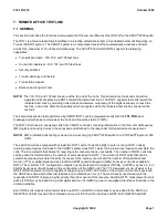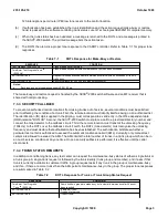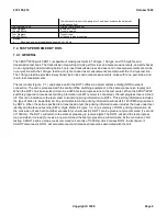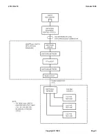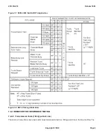
Responders provide 2-way transmission loss and noise measurements and a variety of other measurements of the
trunk under test. The test center controls the measurements of trunks between the near-end office and a far-end
office containing the 105-type test line. All measurement results on the trunk under test are sent back to the test
center in the form of frequency-shift data signals.
The 105 call follows a pattern similar to the 100-type and 102-type test line calls. When the trunk under test has
been seized, the first burst of test progress tone is sent and the directory number of the far-end 105-type test line is
outpulsed. The far-end sends back test progress tone while it is queuing for a responder. The test progress tone is
terminated when the far-end responder is ready. The termination of this test progress tone causes the second burst
of test progress tone to be sent to CAROT by ROTL. After the connection has been established and the far-end
responder has been connected, ROTL makes a bid for the near-end responder at the ROTL office. The third burst
of test progress tone is sent to CAROT while waiting on a responder as in the 102-type test line call. When the
responder is available, control is given to the CAROT Test Center. The test center controls the action of the
responder.
7.4.3.1.2 Loss Measurements
Loss measurements are initiated when the test center sends a 2/6-MF command signal, which requests loss
measurements, to the ROTL responder and to the far-end responder.
The ROTL responder sends the 1200-Hz guard tone to the test center. Simultaneously, the far-end responder sends
a 1004-Hz (1-mw) test tone over the trunk under test. This tone level is to be measured by the ROTL responder.
The ROTL responder measures the 1-kHz signal received from the far-end responder. It converts the measured
loss to a 2200-Hz data tone. Then, the ROTL responder transmits the 2200-Hz data tone to the test center
immediately following the 1200-Hz guard tone. The 2200-Hz data tone is followed by a second 1200-Hz guard tone.
The ROTL responder also transmits a 1000-Hz (1-mw) test tone to the far-end responder after the far-to-near
transmission test has been made. The 1000-Hz test tone transmitted to the far end from the ROTL responder allows
the near-to-far loss on the trunk under test to be measured.
The far-end responder measures the level of the 1000-Hz signal from the ROTL responder. The received signal is
converted to a 2200-Hz data signal which is transmitted back toward the test center along with guard tone on both
sides of the data signal. The value of the measurement is indicated by the length of time that the responder sends
2200 Hz. The relationship between the measurement and length of the 2200-Hz signal is logarithmic. The ROTL
responder detects the 1200-Hz guard tone. When the guard tone is detected, the trunk under test is bridged to the
access connection. The access connection routes the measurement results to the test center. After completing the
loss measurements, the responders return to a signal-receive state awaiting further command signals from the test
center.
7.4.3.1.3 Noise Measurements
Noise measurements are initiated when the test center sends the appropriate 2/6-MF command signals to the ROTL
responder and far-end responder.
The far-end responder terminates the trunk under test. The ROTL responder measures the near-end noise,
converts the measurements into a 2200-Hz data signal, and transmits this signal (as guard-data-guard) to the test
center. The test center then sends a second 2/6-MF signal to the responders.
The far-end responder recognizes the MF signal and measures the far-end noise. During the measurement, the
ROTL responder provides a termination for the trunk under test. The far-end responder transmits a 1200-Hz guard
tone, followed by the 2200-Hz data signal, and then 1200-Hz guard tone toward the test center. The ROTL
responder detects the 1200-Hz guard tone and bridges (cuts through) the trunk under test to the access connection,
so that the guard-data-guard (2200-Hz data signal) from the far-end responder can be sent to the test center. The
responders then return to a signal-receive state awaiting further MF command signals from the center.
235-105-210
October 1999
Copyright © 1999
Page 8
Содержание 5ESS-2000
Страница 96: ...235 105 210 October 1999 Copyright 1999 Page 2 ...
Страница 184: ...235 105 210 October 1999 Copyright 1999 Page 3 ...
Страница 300: ...13 STOP YOU HAVE COMPLETED THIS PROCEDURE 235 105 210 October 1999 Copyright 1999 Page 55 ...
Страница 339: ...7 STOP YOU HAVE COMPLETED THIS PROCEDURE 235 105 210 October 1999 Copyright 1999 Page 13 ...
Страница 342: ...235 105 210 October 1999 Copyright 1999 Page 2 ...
Страница 359: ...235 105 210 October 1999 Copyright 1999 Page 5 ...
Страница 516: ...Figure 10 24 1 KS 23483 L13 Disk Drive Cable Connection Rear View 235 105 210 October 1999 Copyright 1999 Page 2 ...
Страница 517: ...Figure 10 24 2 KS 23483 L21 Disk Drive Cable Connection Rear View 235 105 210 October 1999 Copyright 1999 Page 3 ...
Страница 518: ...Figure 10 24 3 KS 23841 L15 Disk Drive Cable Connection Rear View 235 105 210 October 1999 Copyright 1999 Page 4 ...
Страница 523: ...Figure 10 24 6 Top View of DUP Showing Internal Cabling 235 105 210 October 1999 Copyright 1999 Page 9 ...
Страница 609: ...2 STOP YOU HAVE COMPLETED THIS PROCEDURE 235 105 210 October 1999 Copyright 1999 Page 12 ...
Страница 628: ...a SM inhibited Response OK 2 STOP YOU HAVE COMPLETED THIS PROCEDURE 235 105 210 October 1999 Copyright 1999 Page 8 ...
Страница 653: ...Response OK 2 STOP YOU HAVE COMPLETED THIS PROCEDURE 235 105 210 October 1999 Copyright 1999 Page 16 ...
Страница 676: ...235 105 210 October 1999 Copyright 1999 Page 9 ...
Страница 792: ...3 STOP YOU HAVE COMPLETED THIS PROCEDURE 235 105 210 October 1999 Copyright 1999 Page 9 ...
Страница 799: ...Figure 11 36 3 1 Cleaning Points 235 105 210 October 1999 Copyright 1999 Page 7 ...
Страница 801: ...235 105 210 October 1999 Copyright 1999 Page 9 ...
Страница 839: ...2 STOP YOU HAVE COMPLETED THIS PROCEDURE 235 105 210 October 1999 Copyright 1999 Page 16 ...
Страница 999: ...2 STOP YOU HAVE COMPLETED THIS PROCEDURE 235 105 210 October 1999 Copyright 1999 Page 13 ...
Страница 1008: ...Figure 11 55 1 CTSNS DIP Switch Settings 235 105 210 October 1999 Copyright 1999 Page 2 ...
Страница 1011: ...235 105 210 October 1999 Copyright 1999 Page 5 ...
Страница 1053: ...235 105 210 October 1999 Copyright 1999 Page 15 ...
Страница 1165: ...Procedure 14 14 RESERVED FOR FUTURE USE PROCEDURE 1 Reserved For future use 235 105 210 October 1999 Copyright 1999 Page 1 ...
Страница 1186: ...Procedure 14 17 RESERVED FOR FUTURE USE PROCEDURE 1 Reserved For future use 235 105 210 October 1999 Copyright 1999 Page 1 ...
Страница 1187: ...Procedure 14 18 RESERVED FOR FUTURE USE PROCEDURE 1 Reserved For future use 235 105 210 October 1999 Copyright 1999 Page 1 ...
Страница 1284: ...Figure 15 15 1 PARADYNE Paradyne Corporation 3810 Modem Diagnostic Control Panel 235 105 210 October 1999 Copyright 1999 Page 6 ...
Страница 1287: ...Figure 15 16 1 153A Adapter Connection Figure 15 16 2 AMATPS Block Diagram 235 105 210 October 1999 Copyright 1999 Page 3 ...
Страница 1289: ...Figure 15 17 2 AMATPS Data Link 235 105 210 October 1999 Copyright 1999 Page 2 ...
Страница 1290: ...Figure 15 17 3 Single Housing B25A Cable Assembly 235 105 210 October 1999 Copyright 1999 Page 3 ...
Страница 1292: ...235 105 210 October 1999 Copyright 1999 Page 5 ...
Страница 1294: ...Figure 15 17 8 201C to TN82 Data Set Cable Drawing 235 105 210 October 1999 Copyright 1999 Page 7 ...
Страница 1303: ...9 STOP YOU HAVE COMPLETED THIS PROCEDURE 235 105 210 October 1999 Copyright 1999 Page 2 ...
Страница 1324: ...11 Type and enter q 12 STOP YOU HAVE COMPLETED THIS PROCEDURE 235 105 210 October 1999 Copyright 1999 Page 2 ...
Страница 1342: ...Figure 15 40 1 SCANS II Dial Up Data Set Installation Diagram 235 105 210 October 1999 Copyright 1999 Page 2 ...
Страница 1344: ...Figure 15 40 4 59A1 Mounting Front in Slot J3 Figure 15 40 5 2048A Data Set Front 235 105 210 October 1999 Copyright 1999 Page 4 ...
Страница 1345: ...Figure 15 40 6 Berg Connector Terminations and Layout 235 105 210 October 1999 Copyright 1999 Page 5 ...
Страница 1346: ...Figure 15 40 7 B25A Cable 4 STOP YOU HAVE COMPLETED THIS PROCEDURE 235 105 210 October 1999 Copyright 1999 Page 6 ...
Страница 1360: ...Figure 15 47 2 Typical SCANS III Link Diagram 235 105 210 October 1999 Copyright 1999 Page 2 ...
Страница 1368: ...Response FA or OK appears 17 STOP YOU HAVE COMPLETED THIS PROCEDURE 235 105 210 October 1999 Copyright 1999 Page 2 ...
Страница 1372: ...235 105 210 October 1999 Copyright 1999 Page 2 ...
Страница 1374: ...235 105 210 October 1999 Copyright 1999 Page 4 ...
Страница 1376: ...Figure 15 55 6 201C to TN83 Data Set Cable Drawing 235 105 210 October 1999 Copyright 1999 Page 6 ...
Страница 1418: ...Figure 15 56 1 PARADYNE 3810 Modem Diagnostic Control Panel 235 105 210 October 1999 Copyright 1999 Page 4 ...
Страница 1421: ...Table 1 1 O M Checklist 235 105 210 October 1999 Copyright 1999 Page 3 ...

