


11.10.4 Verify IFAC Data
1.
At the RC/V terminal, type and enter
23
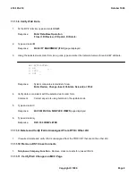
Response:
Enter Data Base Operation
I=Insert, R=Review, U=Update, D=Delete:
2.
Type and enter
R
Response:
FACILITY EQUIPMENT (IFAC)
page displayed. Cursor at SM attribute.
3.
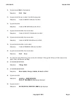
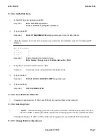
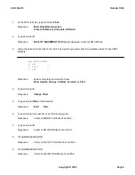
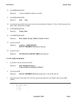
Using the selected work order form as a guide, type and enter the indicated values for the following KEY
attributes:
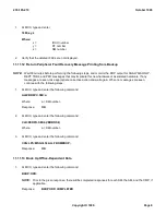
KEY ATTRIBUTES:
1. SM ___
2. IDCU _
3. LSI _
Response:
System completes remainder of view.
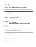
Enter Review, Change-Insert, Validate, Screen#, or Print:
4.
Verify data is consistent with the service order.
Comment:
Correct any errors using terminal in the update mode.
5.
Type and enter
<
Response:
20.0 SM PACK & SUBPACK VIEWS
page displayed.
6.
Type and enter
q
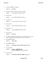
Response:
RCV-196 COMPLETED
11.10.5 Grow IFACs On Other LSI
1.
If required, repeat Sections
11.10.3
and
11.10.4
to grow the IFACs on the other LSI.
11.10.6 Safe Stop Point
1.
NOTE:
If the IFACs being grown are to be used to terminate a remote terminal (RT), then go to
Section
11.10.13
. Making the IFACs operational and testing is part of the RT growth procedures.
Continue with Section
11.10.7
for IFACs which are being grown for use with PUB43801 terminations.
11.10.7 Change IFACs to Operational
235-105-210
October 1999
Copyright © 1999
Page 5
Содержание 5ESS-2000
Страница 96: ...235 105 210 October 1999 Copyright 1999 Page 2 ...
Страница 184: ...235 105 210 October 1999 Copyright 1999 Page 3 ...
Страница 300: ...13 STOP YOU HAVE COMPLETED THIS PROCEDURE 235 105 210 October 1999 Copyright 1999 Page 55 ...
Страница 339: ...7 STOP YOU HAVE COMPLETED THIS PROCEDURE 235 105 210 October 1999 Copyright 1999 Page 13 ...
Страница 342: ...235 105 210 October 1999 Copyright 1999 Page 2 ...
Страница 359: ...235 105 210 October 1999 Copyright 1999 Page 5 ...
Страница 516: ...Figure 10 24 1 KS 23483 L13 Disk Drive Cable Connection Rear View 235 105 210 October 1999 Copyright 1999 Page 2 ...
Страница 517: ...Figure 10 24 2 KS 23483 L21 Disk Drive Cable Connection Rear View 235 105 210 October 1999 Copyright 1999 Page 3 ...
Страница 518: ...Figure 10 24 3 KS 23841 L15 Disk Drive Cable Connection Rear View 235 105 210 October 1999 Copyright 1999 Page 4 ...
Страница 523: ...Figure 10 24 6 Top View of DUP Showing Internal Cabling 235 105 210 October 1999 Copyright 1999 Page 9 ...
Страница 609: ...2 STOP YOU HAVE COMPLETED THIS PROCEDURE 235 105 210 October 1999 Copyright 1999 Page 12 ...
Страница 628: ...a SM inhibited Response OK 2 STOP YOU HAVE COMPLETED THIS PROCEDURE 235 105 210 October 1999 Copyright 1999 Page 8 ...
Страница 653: ...Response OK 2 STOP YOU HAVE COMPLETED THIS PROCEDURE 235 105 210 October 1999 Copyright 1999 Page 16 ...
Страница 676: ...235 105 210 October 1999 Copyright 1999 Page 9 ...
Страница 792: ...3 STOP YOU HAVE COMPLETED THIS PROCEDURE 235 105 210 October 1999 Copyright 1999 Page 9 ...
Страница 799: ...Figure 11 36 3 1 Cleaning Points 235 105 210 October 1999 Copyright 1999 Page 7 ...
Страница 801: ...235 105 210 October 1999 Copyright 1999 Page 9 ...
Страница 839: ...2 STOP YOU HAVE COMPLETED THIS PROCEDURE 235 105 210 October 1999 Copyright 1999 Page 16 ...
Страница 999: ...2 STOP YOU HAVE COMPLETED THIS PROCEDURE 235 105 210 October 1999 Copyright 1999 Page 13 ...
Страница 1008: ...Figure 11 55 1 CTSNS DIP Switch Settings 235 105 210 October 1999 Copyright 1999 Page 2 ...
Страница 1011: ...235 105 210 October 1999 Copyright 1999 Page 5 ...
Страница 1053: ...235 105 210 October 1999 Copyright 1999 Page 15 ...
Страница 1165: ...Procedure 14 14 RESERVED FOR FUTURE USE PROCEDURE 1 Reserved For future use 235 105 210 October 1999 Copyright 1999 Page 1 ...
Страница 1186: ...Procedure 14 17 RESERVED FOR FUTURE USE PROCEDURE 1 Reserved For future use 235 105 210 October 1999 Copyright 1999 Page 1 ...
Страница 1187: ...Procedure 14 18 RESERVED FOR FUTURE USE PROCEDURE 1 Reserved For future use 235 105 210 October 1999 Copyright 1999 Page 1 ...
Страница 1284: ...Figure 15 15 1 PARADYNE Paradyne Corporation 3810 Modem Diagnostic Control Panel 235 105 210 October 1999 Copyright 1999 Page 6 ...
Страница 1287: ...Figure 15 16 1 153A Adapter Connection Figure 15 16 2 AMATPS Block Diagram 235 105 210 October 1999 Copyright 1999 Page 3 ...
Страница 1289: ...Figure 15 17 2 AMATPS Data Link 235 105 210 October 1999 Copyright 1999 Page 2 ...
Страница 1290: ...Figure 15 17 3 Single Housing B25A Cable Assembly 235 105 210 October 1999 Copyright 1999 Page 3 ...
Страница 1292: ...235 105 210 October 1999 Copyright 1999 Page 5 ...
Страница 1294: ...Figure 15 17 8 201C to TN82 Data Set Cable Drawing 235 105 210 October 1999 Copyright 1999 Page 7 ...
Страница 1303: ...9 STOP YOU HAVE COMPLETED THIS PROCEDURE 235 105 210 October 1999 Copyright 1999 Page 2 ...
Страница 1324: ...11 Type and enter q 12 STOP YOU HAVE COMPLETED THIS PROCEDURE 235 105 210 October 1999 Copyright 1999 Page 2 ...
Страница 1342: ...Figure 15 40 1 SCANS II Dial Up Data Set Installation Diagram 235 105 210 October 1999 Copyright 1999 Page 2 ...
Страница 1344: ...Figure 15 40 4 59A1 Mounting Front in Slot J3 Figure 15 40 5 2048A Data Set Front 235 105 210 October 1999 Copyright 1999 Page 4 ...
Страница 1345: ...Figure 15 40 6 Berg Connector Terminations and Layout 235 105 210 October 1999 Copyright 1999 Page 5 ...
Страница 1346: ...Figure 15 40 7 B25A Cable 4 STOP YOU HAVE COMPLETED THIS PROCEDURE 235 105 210 October 1999 Copyright 1999 Page 6 ...
Страница 1360: ...Figure 15 47 2 Typical SCANS III Link Diagram 235 105 210 October 1999 Copyright 1999 Page 2 ...
Страница 1368: ...Response FA or OK appears 17 STOP YOU HAVE COMPLETED THIS PROCEDURE 235 105 210 October 1999 Copyright 1999 Page 2 ...
Страница 1372: ...235 105 210 October 1999 Copyright 1999 Page 2 ...
Страница 1374: ...235 105 210 October 1999 Copyright 1999 Page 4 ...
Страница 1376: ...Figure 15 55 6 201C to TN83 Data Set Cable Drawing 235 105 210 October 1999 Copyright 1999 Page 6 ...
Страница 1418: ...Figure 15 56 1 PARADYNE 3810 Modem Diagnostic Control Panel 235 105 210 October 1999 Copyright 1999 Page 4 ...
Страница 1421: ...Table 1 1 O M Checklist 235 105 210 October 1999 Copyright 1999 Page 3 ...


