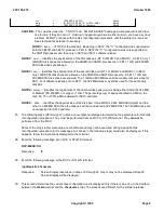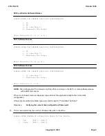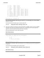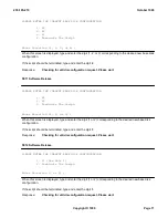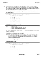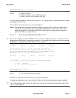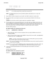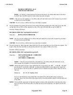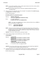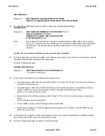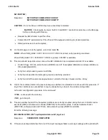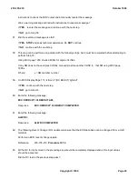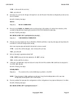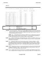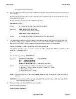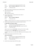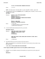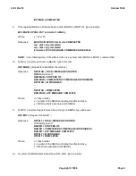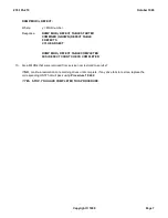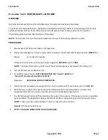
Response:
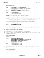
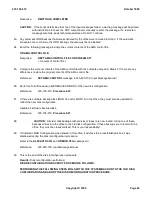
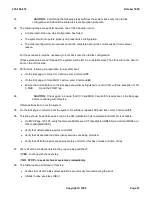
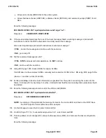
DISK CONFIGURATION AS DETERMINED FROM THE VTOCS AND SG DATA BASE
VTOCS MHD SIZE SG DATA BASE
-------- -------- --------------
Base Disk Configuration = xxxx xxxx
RT 2 (MHD 4 - MHD 5) = wwyy zzzz wwyy
RT 3 (MHD 6 - MHD 7) = wwyy zzzz wwyy
RT 4 (MHD 8 - MHD 9) = wwyy zzzz wwyy
RT 5 (MHD 10 - MHD 11) = wwyy zzzz wwyy
RT 6 (MHD 12 - MHD 13) = wwyy zzzz wwyy
RT 8 (MHD 16 - MHD 17) = wwyy zzzz wwyy
RT 9 (MHD 18 - MHD 19) = wwyy zzzz wwyy
RT 10 (MHD 20 - MHD 21) = wwyy zzzz wwyy
RT 11 (MHD 22 - MHD 23) = wwyy zzzz wwyy
RT 12 (MHD 24 - MHD 25) = wwyy zzzz wwyy
RT 13 (MHD 26 - MHD 27) = wwyy zzzz wwyy
RT 14 (MHD 28 - MHD 29) = wwyy zzzz wwyy
RT 15 (MHD 30 - MHD 31) = wwyy zzzz wwyy
Where:
xxxx
=
63
,
66
,
11
, or unknown
Note 1
uuu
=
1000 or 600
Note 2
vvv
=
1000, 600, 322, 340
Note 3
wwyy
=
[S, M, L)][ 0, 25, 50, 75, or 100% AMA]
Note 4
zzzz
=
1000, 600, 322, 340, or Unknown
Note 5
CAUTION:
The columns under the ``VTOCS'' and ``SG DATA BASE'' headings must agree with each other
line for line. If they do not or if ``Unknown'' appears anywhere in either column, you have a serious
problem. Do NOT continue with the disk reconfiguration procedure until the problem is resolved.
Seek technical assistance if necessary.
NOTE 1:
xxxx
VTOCS of the disk pair. Beginning in 5E12, the "11" configuration is supported on
both the 3B20D and 3B21D processor. Prior to 5E12 the "11" configuration was only supported on
the 3B21D processor and then only in the 5E10 and 5E11 software releases.
NOTE 2:
uuu
Identifies the physical size of the first disk pair (RT 0 or MHD 0 and MHD 1). In 5E12, only 1
GB SCSI disk drives are allowed on the 3B20D and 3B21D processors. In 5E11, 1 GB and 600 MB
SCSI disk drives are allowed.
NOTE 3:
vvv
Identifies the physical size of the second disk pair (RT 1 or MHD 2 and MHD 3). In 5E12,
only 1 GB SCSI disk drives are allowed on the 3B20D and 3B21D processors. In 5E11, 1 GB and
600 MB SCSI disk drives are allowed. The 1 GB and 600 MB are valid secondary disk pair sizes for
5E11. For software releases prior to 5E11, the 322 MB drives may still be used for the secondary
disk pair.
NOTE 4:
wwyy
Identifies the logical size of the optional disk pairs (ww) as being either Small (S) 322 MB,
or Medium (M) 600 MB, or Large (L) 1 GB. The percentage (yy) of space allocated to AMA on the
disk; 50, 75 or 100% AMA is allowed for 5E10 and later.
NOTE 5:
zzzz
Identifies the physical size of the disk pair. If one MHD is a 322 MB SCSI (Small) and the
other is a 600 MB SCSI then the disk pair will be considered a 322 MB SCSI. The 340 MB drives are
235-105-210
October 1999
Copyright © 1999
Page 22
Содержание 5ESS-2000
Страница 96: ...235 105 210 October 1999 Copyright 1999 Page 2 ...
Страница 184: ...235 105 210 October 1999 Copyright 1999 Page 3 ...
Страница 300: ...13 STOP YOU HAVE COMPLETED THIS PROCEDURE 235 105 210 October 1999 Copyright 1999 Page 55 ...
Страница 339: ...7 STOP YOU HAVE COMPLETED THIS PROCEDURE 235 105 210 October 1999 Copyright 1999 Page 13 ...
Страница 342: ...235 105 210 October 1999 Copyright 1999 Page 2 ...
Страница 359: ...235 105 210 October 1999 Copyright 1999 Page 5 ...
Страница 516: ...Figure 10 24 1 KS 23483 L13 Disk Drive Cable Connection Rear View 235 105 210 October 1999 Copyright 1999 Page 2 ...
Страница 517: ...Figure 10 24 2 KS 23483 L21 Disk Drive Cable Connection Rear View 235 105 210 October 1999 Copyright 1999 Page 3 ...
Страница 518: ...Figure 10 24 3 KS 23841 L15 Disk Drive Cable Connection Rear View 235 105 210 October 1999 Copyright 1999 Page 4 ...
Страница 523: ...Figure 10 24 6 Top View of DUP Showing Internal Cabling 235 105 210 October 1999 Copyright 1999 Page 9 ...
Страница 609: ...2 STOP YOU HAVE COMPLETED THIS PROCEDURE 235 105 210 October 1999 Copyright 1999 Page 12 ...
Страница 628: ...a SM inhibited Response OK 2 STOP YOU HAVE COMPLETED THIS PROCEDURE 235 105 210 October 1999 Copyright 1999 Page 8 ...
Страница 653: ...Response OK 2 STOP YOU HAVE COMPLETED THIS PROCEDURE 235 105 210 October 1999 Copyright 1999 Page 16 ...
Страница 676: ...235 105 210 October 1999 Copyright 1999 Page 9 ...
Страница 792: ...3 STOP YOU HAVE COMPLETED THIS PROCEDURE 235 105 210 October 1999 Copyright 1999 Page 9 ...
Страница 799: ...Figure 11 36 3 1 Cleaning Points 235 105 210 October 1999 Copyright 1999 Page 7 ...
Страница 801: ...235 105 210 October 1999 Copyright 1999 Page 9 ...
Страница 839: ...2 STOP YOU HAVE COMPLETED THIS PROCEDURE 235 105 210 October 1999 Copyright 1999 Page 16 ...
Страница 999: ...2 STOP YOU HAVE COMPLETED THIS PROCEDURE 235 105 210 October 1999 Copyright 1999 Page 13 ...
Страница 1008: ...Figure 11 55 1 CTSNS DIP Switch Settings 235 105 210 October 1999 Copyright 1999 Page 2 ...
Страница 1011: ...235 105 210 October 1999 Copyright 1999 Page 5 ...
Страница 1053: ...235 105 210 October 1999 Copyright 1999 Page 15 ...
Страница 1165: ...Procedure 14 14 RESERVED FOR FUTURE USE PROCEDURE 1 Reserved For future use 235 105 210 October 1999 Copyright 1999 Page 1 ...
Страница 1186: ...Procedure 14 17 RESERVED FOR FUTURE USE PROCEDURE 1 Reserved For future use 235 105 210 October 1999 Copyright 1999 Page 1 ...
Страница 1187: ...Procedure 14 18 RESERVED FOR FUTURE USE PROCEDURE 1 Reserved For future use 235 105 210 October 1999 Copyright 1999 Page 1 ...
Страница 1284: ...Figure 15 15 1 PARADYNE Paradyne Corporation 3810 Modem Diagnostic Control Panel 235 105 210 October 1999 Copyright 1999 Page 6 ...
Страница 1287: ...Figure 15 16 1 153A Adapter Connection Figure 15 16 2 AMATPS Block Diagram 235 105 210 October 1999 Copyright 1999 Page 3 ...
Страница 1289: ...Figure 15 17 2 AMATPS Data Link 235 105 210 October 1999 Copyright 1999 Page 2 ...
Страница 1290: ...Figure 15 17 3 Single Housing B25A Cable Assembly 235 105 210 October 1999 Copyright 1999 Page 3 ...
Страница 1292: ...235 105 210 October 1999 Copyright 1999 Page 5 ...
Страница 1294: ...Figure 15 17 8 201C to TN82 Data Set Cable Drawing 235 105 210 October 1999 Copyright 1999 Page 7 ...
Страница 1303: ...9 STOP YOU HAVE COMPLETED THIS PROCEDURE 235 105 210 October 1999 Copyright 1999 Page 2 ...
Страница 1324: ...11 Type and enter q 12 STOP YOU HAVE COMPLETED THIS PROCEDURE 235 105 210 October 1999 Copyright 1999 Page 2 ...
Страница 1342: ...Figure 15 40 1 SCANS II Dial Up Data Set Installation Diagram 235 105 210 October 1999 Copyright 1999 Page 2 ...
Страница 1344: ...Figure 15 40 4 59A1 Mounting Front in Slot J3 Figure 15 40 5 2048A Data Set Front 235 105 210 October 1999 Copyright 1999 Page 4 ...
Страница 1345: ...Figure 15 40 6 Berg Connector Terminations and Layout 235 105 210 October 1999 Copyright 1999 Page 5 ...
Страница 1346: ...Figure 15 40 7 B25A Cable 4 STOP YOU HAVE COMPLETED THIS PROCEDURE 235 105 210 October 1999 Copyright 1999 Page 6 ...
Страница 1360: ...Figure 15 47 2 Typical SCANS III Link Diagram 235 105 210 October 1999 Copyright 1999 Page 2 ...
Страница 1368: ...Response FA or OK appears 17 STOP YOU HAVE COMPLETED THIS PROCEDURE 235 105 210 October 1999 Copyright 1999 Page 2 ...
Страница 1372: ...235 105 210 October 1999 Copyright 1999 Page 2 ...
Страница 1374: ...235 105 210 October 1999 Copyright 1999 Page 4 ...
Страница 1376: ...Figure 15 55 6 201C to TN83 Data Set Cable Drawing 235 105 210 October 1999 Copyright 1999 Page 6 ...
Страница 1418: ...Figure 15 56 1 PARADYNE 3810 Modem Diagnostic Control Panel 235 105 210 October 1999 Copyright 1999 Page 4 ...
Страница 1421: ...Table 1 1 O M Checklist 235 105 210 October 1999 Copyright 1999 Page 3 ...

