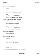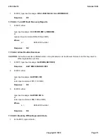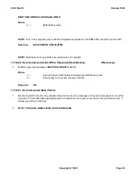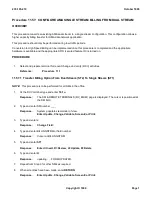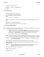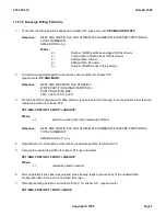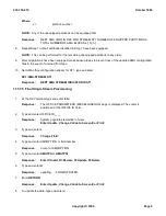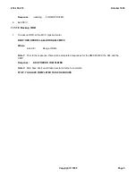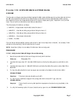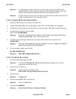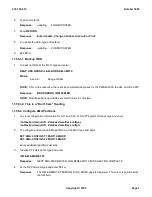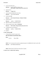
If the diagnostic fails during REX, and only during REX, the failure message along with the TLP will print out.
The message (format defined below) STF RETRY TO FOLLOW will print, then a retry will be done beginning
with the first phase. If the diagnostics (C)ATP on the retry, the diagnostics will be run one more time to verify the
failure.
If the diagnostics (C)ATP on both of these retries, the circuit/unit will then be restored to service. If the
diagnostic fails during either of the retries, the failure will print out along with the TLP, and the circuit/unit will be
considered faulty and will be left OOS. The failure message that will be printed when a retry is going to be done,
will have the following format:
DGN
xyz
=
a
COMPLETED STF RETRY TO FOLLOW
Where:
xyz
is the circuit/unit being diagnosed and
a
is the circuit/unit number.
NOTE:
Due to the severity of type of diagnostic failure, some failures may not cause a retry to be done;
therefore, if the diagnostic fails, it will stop, no retry done, and the circuit/unit will be left OOS.
Partial diagnostic (SWITCH):
SWITCH results in a soft switch of the communication module processor
(CMP), the pump peripheral controller (PPC), the foundation peripheral controller (FPC), and the office network
and timing complex (ONTC). No diagnostics are executed.
In the SM/SM-2000, three test types can be specified. They are as follows:
Full diagnostic (DGN):
A full diagnostic results in a conditional restore request including the trouble location
procedure (TLP) option. A conditional restore consists of: a remove of the target unit/circuit, a full diagnostic on
the unit/circuit, and a restore of the unit/circuit to service if the diagnostic result was all tests pass (ATP) or
conditional all tests pass (CATP).
If the diagnostic fails during REX, and only during REX, the failure message along with the TLP will print out.
The message (format defined below) STF RETRY TO FOLLOW will print, then a retry will be done beginning
with the first phase. If the diagnostics (C)ATP on the retry, the diagnostics will be run one more time to verify the
failure. If the diagnostics (C)ATP on both of these retries, the circuit/unit will then be restored to service. If the
diagnostic fails during either of the retries, the failure will print out along with the TLP, and the circuit/unit will be
considered faulty and will be left OOS or put in the degraded state. The failure message that will be printed
when a retry is going to be done, will have the following format:
DGN xyz=a COMPLETED STF RETRY TO FOLLOW
Where:
xyz
is the circuit/unit being diagnosed and
a
is the circuit/unit number.
NOTE:
Due to the severity of type of diagnostic failure, some failures may not cause a retry to be done;
therefore, if the diagnostic fails, it will stop, no retry done, and the circuit/unit will be left OOS or
degraded.
Fabric exerciser (FAB):
The FAB tests the operation of the gated diode crosspoints (GDX) in the line unit (LU)
concentrator grids and grid boards. It requests a path to each crosspoint to be tested by calling peripheral
control (PC) path hunt routines. A series of tests are then performed on the crosspoint and its associated path
using a high-level service circuit (HLSC).
Electronic loop segregation (ELS):
ELS tests customer lines to determine a suitable network balance
necessary to reduce the amount of potential echoing in the transmission path. Office data is updated, as
needed, storing the proper balance network value to be used in call setup.
The following comments apply to both CM and SM/SM-2000 diagnostics. A global parameter can be modified using
235-105-210
October 1999
Copyright © 1999
Page 2
Содержание 5ESS-2000
Страница 96: ...235 105 210 October 1999 Copyright 1999 Page 2 ...
Страница 184: ...235 105 210 October 1999 Copyright 1999 Page 3 ...
Страница 300: ...13 STOP YOU HAVE COMPLETED THIS PROCEDURE 235 105 210 October 1999 Copyright 1999 Page 55 ...
Страница 339: ...7 STOP YOU HAVE COMPLETED THIS PROCEDURE 235 105 210 October 1999 Copyright 1999 Page 13 ...
Страница 342: ...235 105 210 October 1999 Copyright 1999 Page 2 ...
Страница 359: ...235 105 210 October 1999 Copyright 1999 Page 5 ...
Страница 516: ...Figure 10 24 1 KS 23483 L13 Disk Drive Cable Connection Rear View 235 105 210 October 1999 Copyright 1999 Page 2 ...
Страница 517: ...Figure 10 24 2 KS 23483 L21 Disk Drive Cable Connection Rear View 235 105 210 October 1999 Copyright 1999 Page 3 ...
Страница 518: ...Figure 10 24 3 KS 23841 L15 Disk Drive Cable Connection Rear View 235 105 210 October 1999 Copyright 1999 Page 4 ...
Страница 523: ...Figure 10 24 6 Top View of DUP Showing Internal Cabling 235 105 210 October 1999 Copyright 1999 Page 9 ...
Страница 609: ...2 STOP YOU HAVE COMPLETED THIS PROCEDURE 235 105 210 October 1999 Copyright 1999 Page 12 ...
Страница 628: ...a SM inhibited Response OK 2 STOP YOU HAVE COMPLETED THIS PROCEDURE 235 105 210 October 1999 Copyright 1999 Page 8 ...
Страница 653: ...Response OK 2 STOP YOU HAVE COMPLETED THIS PROCEDURE 235 105 210 October 1999 Copyright 1999 Page 16 ...
Страница 676: ...235 105 210 October 1999 Copyright 1999 Page 9 ...
Страница 792: ...3 STOP YOU HAVE COMPLETED THIS PROCEDURE 235 105 210 October 1999 Copyright 1999 Page 9 ...
Страница 799: ...Figure 11 36 3 1 Cleaning Points 235 105 210 October 1999 Copyright 1999 Page 7 ...
Страница 801: ...235 105 210 October 1999 Copyright 1999 Page 9 ...
Страница 839: ...2 STOP YOU HAVE COMPLETED THIS PROCEDURE 235 105 210 October 1999 Copyright 1999 Page 16 ...
Страница 999: ...2 STOP YOU HAVE COMPLETED THIS PROCEDURE 235 105 210 October 1999 Copyright 1999 Page 13 ...
Страница 1008: ...Figure 11 55 1 CTSNS DIP Switch Settings 235 105 210 October 1999 Copyright 1999 Page 2 ...
Страница 1011: ...235 105 210 October 1999 Copyright 1999 Page 5 ...
Страница 1053: ...235 105 210 October 1999 Copyright 1999 Page 15 ...
Страница 1165: ...Procedure 14 14 RESERVED FOR FUTURE USE PROCEDURE 1 Reserved For future use 235 105 210 October 1999 Copyright 1999 Page 1 ...
Страница 1186: ...Procedure 14 17 RESERVED FOR FUTURE USE PROCEDURE 1 Reserved For future use 235 105 210 October 1999 Copyright 1999 Page 1 ...
Страница 1187: ...Procedure 14 18 RESERVED FOR FUTURE USE PROCEDURE 1 Reserved For future use 235 105 210 October 1999 Copyright 1999 Page 1 ...
Страница 1284: ...Figure 15 15 1 PARADYNE Paradyne Corporation 3810 Modem Diagnostic Control Panel 235 105 210 October 1999 Copyright 1999 Page 6 ...
Страница 1287: ...Figure 15 16 1 153A Adapter Connection Figure 15 16 2 AMATPS Block Diagram 235 105 210 October 1999 Copyright 1999 Page 3 ...
Страница 1289: ...Figure 15 17 2 AMATPS Data Link 235 105 210 October 1999 Copyright 1999 Page 2 ...
Страница 1290: ...Figure 15 17 3 Single Housing B25A Cable Assembly 235 105 210 October 1999 Copyright 1999 Page 3 ...
Страница 1292: ...235 105 210 October 1999 Copyright 1999 Page 5 ...
Страница 1294: ...Figure 15 17 8 201C to TN82 Data Set Cable Drawing 235 105 210 October 1999 Copyright 1999 Page 7 ...
Страница 1303: ...9 STOP YOU HAVE COMPLETED THIS PROCEDURE 235 105 210 October 1999 Copyright 1999 Page 2 ...
Страница 1324: ...11 Type and enter q 12 STOP YOU HAVE COMPLETED THIS PROCEDURE 235 105 210 October 1999 Copyright 1999 Page 2 ...
Страница 1342: ...Figure 15 40 1 SCANS II Dial Up Data Set Installation Diagram 235 105 210 October 1999 Copyright 1999 Page 2 ...
Страница 1344: ...Figure 15 40 4 59A1 Mounting Front in Slot J3 Figure 15 40 5 2048A Data Set Front 235 105 210 October 1999 Copyright 1999 Page 4 ...
Страница 1345: ...Figure 15 40 6 Berg Connector Terminations and Layout 235 105 210 October 1999 Copyright 1999 Page 5 ...
Страница 1346: ...Figure 15 40 7 B25A Cable 4 STOP YOU HAVE COMPLETED THIS PROCEDURE 235 105 210 October 1999 Copyright 1999 Page 6 ...
Страница 1360: ...Figure 15 47 2 Typical SCANS III Link Diagram 235 105 210 October 1999 Copyright 1999 Page 2 ...
Страница 1368: ...Response FA or OK appears 17 STOP YOU HAVE COMPLETED THIS PROCEDURE 235 105 210 October 1999 Copyright 1999 Page 2 ...
Страница 1372: ...235 105 210 October 1999 Copyright 1999 Page 2 ...
Страница 1374: ...235 105 210 October 1999 Copyright 1999 Page 4 ...
Страница 1376: ...Figure 15 55 6 201C to TN83 Data Set Cable Drawing 235 105 210 October 1999 Copyright 1999 Page 6 ...
Страница 1418: ...Figure 15 56 1 PARADYNE 3810 Modem Diagnostic Control Panel 235 105 210 October 1999 Copyright 1999 Page 4 ...
Страница 1421: ...Table 1 1 O M Checklist 235 105 210 October 1999 Copyright 1999 Page 3 ...

