update in the 5ESS-2000 switch.
If all software updates in the active log have been made official and memory space used by the old version of the
replaced functions has been reclaimed, the history of these software updates may be stored in the archive log to
conserve disk space. Subsequently, these histories may be printed on the MCC printer by typing ``9104,backlog''.
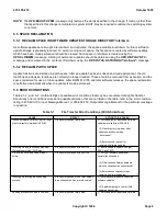
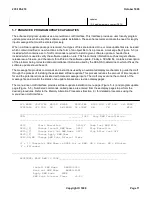
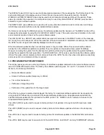
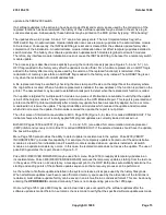
The updates shown in Figures 5-6 and 5-7 are in a temporary state. The most important status flag is the
INSTALLED flag. An administrative module initialization can cause temporary updates in the administrative module
to be removed. Consequently, the INSTALLED flag is reset and is cleared from the software update history after
completion of the initialization. An administrative module initialization does not affect temporary updates installed in
switch modules. The history of a software update which updates switch modules is global to all switch modules.
Therefore, any interface module initialization does not cause the INSTALLED flag to be reset for a temporary switch
module update.
The process type is described more explicitly by using the correct process types (see Figures 5-6 and 5-7 ). An
OFC flag is added to the history entry after the update is made official. For a function replacement, an AUDT flag is
added to the history after memory space used by the version of the replaced function(s) is reclaimed. If the
reclamation of memory space fails, an AUDABT flag is added to the history entry instead. The AUDABT flag is set
only when the reclamation of non-AM updates fails.
A file replacement may be verified by checking the time stamp and file size on the target file at the directory where
the original file is located. When a function replacement is installed, the new address of the function is printed on the
printer. The new address may be used to establish a breakpoint to detect when the replacement function is called.
If an update is targeted for multiple switch modules, two pieces of information are available to verify that the update
is in all of the target modules. The first piece of information is the UPD Module Report. This report is generated and
printed on the MCC printer automatically after a temporary update has been successfully applied, but one or more
modules did not receive the update. The report identifies all modules which received the update and all modules
which did not receive the update. If all modules received the update, the report is not printed.
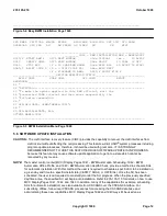
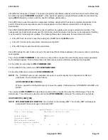
The other piece of information is available on MCC Page 1800 (Figure 5-8 ). Box 10 is called UPDBACKOUT. This
indicator shows whether or not recently applied SM program updates are currently loaded or backed out.
Both MCC Pages 1850 and 1851 (Figures 5-9 and 5-10 ) are added for communication module processor
(CMP) inhibit and recovery control. Box 10 is called UPDBACKOUT. If the selected module
should
have the update,
the box will be lighted.
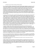
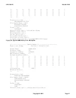
Menu Page 1950 also provides the ability to detect update inconsistencies in the system. Poke 9200 (VERIFY
INCONSISTENCY) provides this capability. For example, if a temporary update is booted out of the administrative
module as a result of an initialization and if a switch module is isolated when an update is installed in all switch
modules, an update inconsistency occurs. In this case, the isolated module does not receive the update. The use of
poke 9200 generates the report shown in Figure 5-11 .
Poke 9300 (RECOVER FORWARD) may be used from menu Page 1950 to reapply all temporary updates in an
inconsistent state. Poke 9400 (RECOVER BACKWARD) removes the temporary updates, starting from the last one
in the system. If there is no inconsistency, a message will print to the ROP. Both pokes automatically determine the
starting and ending points of the software update sequence so that a recovery process can be performed.
As the number of software updates installed in the system increases, disk space used by the history files grows.
When all software updates have been made official and memory space used by the old version of the functions is
reclaimed, most software update history can be saved in an archive file in a condensed format. This can be done by
entering the
UPD:REDUCE
command manually. There is no corresponding poke on the 1950 page.
On menu Page 1950, poke 9600 may be used in clear disk space occupied by the software updates after the
software update is made official. An automatic check is made to verify that the specified software update was made
235-105-210
October 1999
Copyright © 1999
Page 15
Содержание 5ESS-2000
Страница 96: ...235 105 210 October 1999 Copyright 1999 Page 2 ...
Страница 184: ...235 105 210 October 1999 Copyright 1999 Page 3 ...
Страница 300: ...13 STOP YOU HAVE COMPLETED THIS PROCEDURE 235 105 210 October 1999 Copyright 1999 Page 55 ...
Страница 339: ...7 STOP YOU HAVE COMPLETED THIS PROCEDURE 235 105 210 October 1999 Copyright 1999 Page 13 ...
Страница 342: ...235 105 210 October 1999 Copyright 1999 Page 2 ...
Страница 359: ...235 105 210 October 1999 Copyright 1999 Page 5 ...
Страница 516: ...Figure 10 24 1 KS 23483 L13 Disk Drive Cable Connection Rear View 235 105 210 October 1999 Copyright 1999 Page 2 ...
Страница 517: ...Figure 10 24 2 KS 23483 L21 Disk Drive Cable Connection Rear View 235 105 210 October 1999 Copyright 1999 Page 3 ...
Страница 518: ...Figure 10 24 3 KS 23841 L15 Disk Drive Cable Connection Rear View 235 105 210 October 1999 Copyright 1999 Page 4 ...
Страница 523: ...Figure 10 24 6 Top View of DUP Showing Internal Cabling 235 105 210 October 1999 Copyright 1999 Page 9 ...
Страница 609: ...2 STOP YOU HAVE COMPLETED THIS PROCEDURE 235 105 210 October 1999 Copyright 1999 Page 12 ...
Страница 628: ...a SM inhibited Response OK 2 STOP YOU HAVE COMPLETED THIS PROCEDURE 235 105 210 October 1999 Copyright 1999 Page 8 ...
Страница 653: ...Response OK 2 STOP YOU HAVE COMPLETED THIS PROCEDURE 235 105 210 October 1999 Copyright 1999 Page 16 ...
Страница 676: ...235 105 210 October 1999 Copyright 1999 Page 9 ...
Страница 792: ...3 STOP YOU HAVE COMPLETED THIS PROCEDURE 235 105 210 October 1999 Copyright 1999 Page 9 ...
Страница 799: ...Figure 11 36 3 1 Cleaning Points 235 105 210 October 1999 Copyright 1999 Page 7 ...
Страница 801: ...235 105 210 October 1999 Copyright 1999 Page 9 ...
Страница 839: ...2 STOP YOU HAVE COMPLETED THIS PROCEDURE 235 105 210 October 1999 Copyright 1999 Page 16 ...
Страница 999: ...2 STOP YOU HAVE COMPLETED THIS PROCEDURE 235 105 210 October 1999 Copyright 1999 Page 13 ...
Страница 1008: ...Figure 11 55 1 CTSNS DIP Switch Settings 235 105 210 October 1999 Copyright 1999 Page 2 ...
Страница 1011: ...235 105 210 October 1999 Copyright 1999 Page 5 ...
Страница 1053: ...235 105 210 October 1999 Copyright 1999 Page 15 ...
Страница 1165: ...Procedure 14 14 RESERVED FOR FUTURE USE PROCEDURE 1 Reserved For future use 235 105 210 October 1999 Copyright 1999 Page 1 ...
Страница 1186: ...Procedure 14 17 RESERVED FOR FUTURE USE PROCEDURE 1 Reserved For future use 235 105 210 October 1999 Copyright 1999 Page 1 ...
Страница 1187: ...Procedure 14 18 RESERVED FOR FUTURE USE PROCEDURE 1 Reserved For future use 235 105 210 October 1999 Copyright 1999 Page 1 ...
Страница 1284: ...Figure 15 15 1 PARADYNE Paradyne Corporation 3810 Modem Diagnostic Control Panel 235 105 210 October 1999 Copyright 1999 Page 6 ...
Страница 1287: ...Figure 15 16 1 153A Adapter Connection Figure 15 16 2 AMATPS Block Diagram 235 105 210 October 1999 Copyright 1999 Page 3 ...
Страница 1289: ...Figure 15 17 2 AMATPS Data Link 235 105 210 October 1999 Copyright 1999 Page 2 ...
Страница 1290: ...Figure 15 17 3 Single Housing B25A Cable Assembly 235 105 210 October 1999 Copyright 1999 Page 3 ...
Страница 1292: ...235 105 210 October 1999 Copyright 1999 Page 5 ...
Страница 1294: ...Figure 15 17 8 201C to TN82 Data Set Cable Drawing 235 105 210 October 1999 Copyright 1999 Page 7 ...
Страница 1303: ...9 STOP YOU HAVE COMPLETED THIS PROCEDURE 235 105 210 October 1999 Copyright 1999 Page 2 ...
Страница 1324: ...11 Type and enter q 12 STOP YOU HAVE COMPLETED THIS PROCEDURE 235 105 210 October 1999 Copyright 1999 Page 2 ...
Страница 1342: ...Figure 15 40 1 SCANS II Dial Up Data Set Installation Diagram 235 105 210 October 1999 Copyright 1999 Page 2 ...
Страница 1344: ...Figure 15 40 4 59A1 Mounting Front in Slot J3 Figure 15 40 5 2048A Data Set Front 235 105 210 October 1999 Copyright 1999 Page 4 ...
Страница 1345: ...Figure 15 40 6 Berg Connector Terminations and Layout 235 105 210 October 1999 Copyright 1999 Page 5 ...
Страница 1346: ...Figure 15 40 7 B25A Cable 4 STOP YOU HAVE COMPLETED THIS PROCEDURE 235 105 210 October 1999 Copyright 1999 Page 6 ...
Страница 1360: ...Figure 15 47 2 Typical SCANS III Link Diagram 235 105 210 October 1999 Copyright 1999 Page 2 ...
Страница 1368: ...Response FA or OK appears 17 STOP YOU HAVE COMPLETED THIS PROCEDURE 235 105 210 October 1999 Copyright 1999 Page 2 ...
Страница 1372: ...235 105 210 October 1999 Copyright 1999 Page 2 ...
Страница 1374: ...235 105 210 October 1999 Copyright 1999 Page 4 ...
Страница 1376: ...Figure 15 55 6 201C to TN83 Data Set Cable Drawing 235 105 210 October 1999 Copyright 1999 Page 6 ...
Страница 1418: ...Figure 15 56 1 PARADYNE 3810 Modem Diagnostic Control Panel 235 105 210 October 1999 Copyright 1999 Page 4 ...
Страница 1421: ...Table 1 1 O M Checklist 235 105 210 October 1999 Copyright 1999 Page 3 ...

