


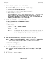
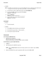


Procedure 6.35: LOAD A CARTRIDGE TAPE IN A SCSI DAT DRIVE (3B21D)
OVERVIEW
The Small Computer System Interface (SCSI) Digital Audio Tape (DAT) Drive has the following indentification and
associated circuit pack:
SCSI DAT DRIVE
CIRCUIT PACK
(Figure 6.35-1 ).
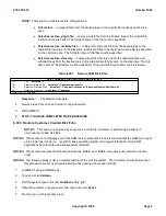
NCR006-3503341
UN376, UN376B
NCR006-3300608
UN376C
CAUTION:
Although the manufacturer designed the drive mechanism to prevent the cartridge from being
over-inserted, excessive insertion force will damage the drive mechanism components. The cartridge
should be inserted gently into the drive. Very little force is required to cause the drive to grab the
cartridge, after which, the drive will pull the cartridge into the drive. Excessive force WILL damage the
tape loading mechanism.
NOTE:
For specific information on the
5ESS
®
-2000 Switch Very Compact Digital Exchange (VCDX), refer to
235-120-110 (
Very Compact Digital Exchange Reference Guide
) and 235-120-120 (
Very Compact Digital
Exchange User's Guide
).
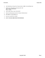
PROCEDURE
1.
Is the tape activity a "read only" operation?
If
YES
, continue with next step.
If
NO
, go to Step 3.
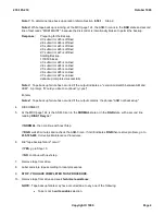
2.
Write protect the cartridge by sliding the tab on the rear of the cartridge so that the hole is open (Figure
6.35-2 ).
3.
Gently insert the cartridge tape into the drive until the drive takes hold of the cartridge. This starts the loading
sequence. The drive rewinds the tape to
BOT
and goes on line.
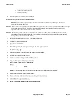
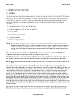
4.
Is a "Caution" indicated on the front panel of the DAT drive circuit pack?
NOTE:
A "Caution" signal (high error rate) is a wellness check that could be a poor quality cassette or tape
heads may require cleaning. The "Caution" is identified by the following LED display:
Condition
Cassette
Drive
Indicator
Indicator
Caution
UN376 and UN376B
Green
Alternating Flashing
Green and Amber
UN376C
Any State
Pulse Amber
If
YES
, continue with next step.
If
NO
, go to Step 6.
5.
If a new cartridge is being used, replace the cartridge and repeat the procedure. If the caution indication
remains, the tape heads may require cleaning (refer to Procedure 4.21 ). Seek technical assistance.
6.
Tape is loaded in the DAT drive.
235-105-210
October 1999
Copyright © 1999
Page 1
Содержание 5ESS-2000
Страница 96: ...235 105 210 October 1999 Copyright 1999 Page 2 ...
Страница 184: ...235 105 210 October 1999 Copyright 1999 Page 3 ...
Страница 300: ...13 STOP YOU HAVE COMPLETED THIS PROCEDURE 235 105 210 October 1999 Copyright 1999 Page 55 ...
Страница 339: ...7 STOP YOU HAVE COMPLETED THIS PROCEDURE 235 105 210 October 1999 Copyright 1999 Page 13 ...
Страница 342: ...235 105 210 October 1999 Copyright 1999 Page 2 ...
Страница 359: ...235 105 210 October 1999 Copyright 1999 Page 5 ...
Страница 516: ...Figure 10 24 1 KS 23483 L13 Disk Drive Cable Connection Rear View 235 105 210 October 1999 Copyright 1999 Page 2 ...
Страница 517: ...Figure 10 24 2 KS 23483 L21 Disk Drive Cable Connection Rear View 235 105 210 October 1999 Copyright 1999 Page 3 ...
Страница 518: ...Figure 10 24 3 KS 23841 L15 Disk Drive Cable Connection Rear View 235 105 210 October 1999 Copyright 1999 Page 4 ...
Страница 523: ...Figure 10 24 6 Top View of DUP Showing Internal Cabling 235 105 210 October 1999 Copyright 1999 Page 9 ...
Страница 609: ...2 STOP YOU HAVE COMPLETED THIS PROCEDURE 235 105 210 October 1999 Copyright 1999 Page 12 ...
Страница 628: ...a SM inhibited Response OK 2 STOP YOU HAVE COMPLETED THIS PROCEDURE 235 105 210 October 1999 Copyright 1999 Page 8 ...
Страница 653: ...Response OK 2 STOP YOU HAVE COMPLETED THIS PROCEDURE 235 105 210 October 1999 Copyright 1999 Page 16 ...
Страница 676: ...235 105 210 October 1999 Copyright 1999 Page 9 ...
Страница 792: ...3 STOP YOU HAVE COMPLETED THIS PROCEDURE 235 105 210 October 1999 Copyright 1999 Page 9 ...
Страница 799: ...Figure 11 36 3 1 Cleaning Points 235 105 210 October 1999 Copyright 1999 Page 7 ...
Страница 801: ...235 105 210 October 1999 Copyright 1999 Page 9 ...
Страница 839: ...2 STOP YOU HAVE COMPLETED THIS PROCEDURE 235 105 210 October 1999 Copyright 1999 Page 16 ...
Страница 999: ...2 STOP YOU HAVE COMPLETED THIS PROCEDURE 235 105 210 October 1999 Copyright 1999 Page 13 ...
Страница 1008: ...Figure 11 55 1 CTSNS DIP Switch Settings 235 105 210 October 1999 Copyright 1999 Page 2 ...
Страница 1011: ...235 105 210 October 1999 Copyright 1999 Page 5 ...
Страница 1053: ...235 105 210 October 1999 Copyright 1999 Page 15 ...
Страница 1165: ...Procedure 14 14 RESERVED FOR FUTURE USE PROCEDURE 1 Reserved For future use 235 105 210 October 1999 Copyright 1999 Page 1 ...
Страница 1186: ...Procedure 14 17 RESERVED FOR FUTURE USE PROCEDURE 1 Reserved For future use 235 105 210 October 1999 Copyright 1999 Page 1 ...
Страница 1187: ...Procedure 14 18 RESERVED FOR FUTURE USE PROCEDURE 1 Reserved For future use 235 105 210 October 1999 Copyright 1999 Page 1 ...
Страница 1284: ...Figure 15 15 1 PARADYNE Paradyne Corporation 3810 Modem Diagnostic Control Panel 235 105 210 October 1999 Copyright 1999 Page 6 ...
Страница 1287: ...Figure 15 16 1 153A Adapter Connection Figure 15 16 2 AMATPS Block Diagram 235 105 210 October 1999 Copyright 1999 Page 3 ...
Страница 1289: ...Figure 15 17 2 AMATPS Data Link 235 105 210 October 1999 Copyright 1999 Page 2 ...
Страница 1290: ...Figure 15 17 3 Single Housing B25A Cable Assembly 235 105 210 October 1999 Copyright 1999 Page 3 ...
Страница 1292: ...235 105 210 October 1999 Copyright 1999 Page 5 ...
Страница 1294: ...Figure 15 17 8 201C to TN82 Data Set Cable Drawing 235 105 210 October 1999 Copyright 1999 Page 7 ...
Страница 1303: ...9 STOP YOU HAVE COMPLETED THIS PROCEDURE 235 105 210 October 1999 Copyright 1999 Page 2 ...
Страница 1324: ...11 Type and enter q 12 STOP YOU HAVE COMPLETED THIS PROCEDURE 235 105 210 October 1999 Copyright 1999 Page 2 ...
Страница 1342: ...Figure 15 40 1 SCANS II Dial Up Data Set Installation Diagram 235 105 210 October 1999 Copyright 1999 Page 2 ...
Страница 1344: ...Figure 15 40 4 59A1 Mounting Front in Slot J3 Figure 15 40 5 2048A Data Set Front 235 105 210 October 1999 Copyright 1999 Page 4 ...
Страница 1345: ...Figure 15 40 6 Berg Connector Terminations and Layout 235 105 210 October 1999 Copyright 1999 Page 5 ...
Страница 1346: ...Figure 15 40 7 B25A Cable 4 STOP YOU HAVE COMPLETED THIS PROCEDURE 235 105 210 October 1999 Copyright 1999 Page 6 ...
Страница 1360: ...Figure 15 47 2 Typical SCANS III Link Diagram 235 105 210 October 1999 Copyright 1999 Page 2 ...
Страница 1368: ...Response FA or OK appears 17 STOP YOU HAVE COMPLETED THIS PROCEDURE 235 105 210 October 1999 Copyright 1999 Page 2 ...
Страница 1372: ...235 105 210 October 1999 Copyright 1999 Page 2 ...
Страница 1374: ...235 105 210 October 1999 Copyright 1999 Page 4 ...
Страница 1376: ...Figure 15 55 6 201C to TN83 Data Set Cable Drawing 235 105 210 October 1999 Copyright 1999 Page 6 ...
Страница 1418: ...Figure 15 56 1 PARADYNE 3810 Modem Diagnostic Control Panel 235 105 210 October 1999 Copyright 1999 Page 4 ...
Страница 1421: ...Table 1 1 O M Checklist 235 105 210 October 1999 Copyright 1999 Page 3 ...


