9. MOVING HEAD DISK PROCEDURE DESCRIPTION
9.1 OVERVIEW
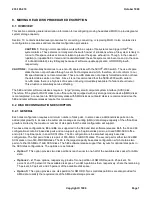
This section contains general description information for reconfiguring moving head disks (MHD) to provide greater
system storage capacity.
Section 10 contains detailed level procedures for converting, connecting, or replacing MHD. It also contains disk
reconfiguration procedures and remote disk configuration procedures.
CAUTION 1:
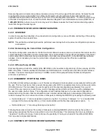
During normal operations, work within a couple of file systems can trigger
UNIX
®
file
system alarms. These alarms normally warn the switch owner of situations where a file system is likely to
run out of file space unless actions are taken to prevent the space exhaustion. Though, in the cases of
/updtmp (or /update 5E9 or later) and /nododd/imdataX, these file systems can become and (in the case
of /no5odd/imdataX), stay full legally because of software update application or NRODD growth,
respectively.
CAUTION 2:
It is potentially hazardous to use non-KS spare disks with the
5ESS
®
-2000 switch. The use of spare
disks that are not purchased through Lucent Technologies and which, therefore, do not conform to our
KS specifications is not recommended. These non-KS disks are not properly formatted and do not have
the defect tables written on them. Since it is not recommended that the 5ESS-2000 switch write to
non-KS disks, there is a high risk of a spare not being immediately available if a failure should occur.
This situation is potentially service affecting.
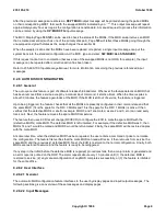
The 5E9 and later software releases require a ``large'' primary small computer system interface (SCSI) disk.
Therefore, if the growth of SCSI disks to an office currently equipped with only storage module device (SMD) disks
is contemplated, a conversion to SCSI primary disks with SMD disks as outboard disks is recommended since the
5E9 and later software releases require this conversion.
9.2 DISK RECONFIGURATION DESCRIPTION
9.2.1 GENERAL
Each disk configuration requires a minimum number of disk pairs. In some cases, additional disks pairs can be
added (disk growth) to increase the automatic message accounting (AMA) data storage capacity of the office. Disk
growth is limited by the maximum number of disk pairs that the disk configuration will support.
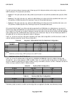
Two base disk configurations,
63
and
66
, are supported in the 5E9 and later software releases. Both the 63 and 66
configurations contain 2 base disk pairs and can support up to 5 optional disk pairs in a mixed SMD-SCSI office,
and up to 13 optional pairs in an all SCSI office. The 63 configuration is the smallest capacity base disk
configuration. The first pair of disks is a pair of 600-MB or 1-GB SCSI disks. The second pair is either two 322-MB
SCSI disks or two 340-MB SMD disks. The 66 is the largest capacity base disk configuration which contains two
pairs of either 600-MB or 1-GB SCSI disks. The 5E9 software release support five layouts for optional disk pairs in
the SCSI disk configurations. The options are as follows:
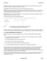
Option 1:
This option provides two disk partitions (each equal to one-half of the available disk space) for AMA
data.
Options 2 - 4:
These options, respectively, provide for one partition of SM ODD equal to 25 percent, 50
percent, and 75 percent of the available disk space. Two AMA partitions then, respectively, share the remaining
75 percent, 50 percent, and 25 percent of the available disk space.
Option 5:
This option provides one disk partition for SM ODD. Two small disk partitions are also provided for
AMA data to satisfy the requirements of the AMA data storage process.
235-105-210
October 1999
Copyright © 1999
Page 1
Содержание 5ESS-2000
Страница 96: ...235 105 210 October 1999 Copyright 1999 Page 2 ...
Страница 184: ...235 105 210 October 1999 Copyright 1999 Page 3 ...
Страница 300: ...13 STOP YOU HAVE COMPLETED THIS PROCEDURE 235 105 210 October 1999 Copyright 1999 Page 55 ...
Страница 339: ...7 STOP YOU HAVE COMPLETED THIS PROCEDURE 235 105 210 October 1999 Copyright 1999 Page 13 ...
Страница 342: ...235 105 210 October 1999 Copyright 1999 Page 2 ...
Страница 359: ...235 105 210 October 1999 Copyright 1999 Page 5 ...
Страница 516: ...Figure 10 24 1 KS 23483 L13 Disk Drive Cable Connection Rear View 235 105 210 October 1999 Copyright 1999 Page 2 ...
Страница 517: ...Figure 10 24 2 KS 23483 L21 Disk Drive Cable Connection Rear View 235 105 210 October 1999 Copyright 1999 Page 3 ...
Страница 518: ...Figure 10 24 3 KS 23841 L15 Disk Drive Cable Connection Rear View 235 105 210 October 1999 Copyright 1999 Page 4 ...
Страница 523: ...Figure 10 24 6 Top View of DUP Showing Internal Cabling 235 105 210 October 1999 Copyright 1999 Page 9 ...
Страница 609: ...2 STOP YOU HAVE COMPLETED THIS PROCEDURE 235 105 210 October 1999 Copyright 1999 Page 12 ...
Страница 628: ...a SM inhibited Response OK 2 STOP YOU HAVE COMPLETED THIS PROCEDURE 235 105 210 October 1999 Copyright 1999 Page 8 ...
Страница 653: ...Response OK 2 STOP YOU HAVE COMPLETED THIS PROCEDURE 235 105 210 October 1999 Copyright 1999 Page 16 ...
Страница 676: ...235 105 210 October 1999 Copyright 1999 Page 9 ...
Страница 792: ...3 STOP YOU HAVE COMPLETED THIS PROCEDURE 235 105 210 October 1999 Copyright 1999 Page 9 ...
Страница 799: ...Figure 11 36 3 1 Cleaning Points 235 105 210 October 1999 Copyright 1999 Page 7 ...
Страница 801: ...235 105 210 October 1999 Copyright 1999 Page 9 ...
Страница 839: ...2 STOP YOU HAVE COMPLETED THIS PROCEDURE 235 105 210 October 1999 Copyright 1999 Page 16 ...
Страница 999: ...2 STOP YOU HAVE COMPLETED THIS PROCEDURE 235 105 210 October 1999 Copyright 1999 Page 13 ...
Страница 1008: ...Figure 11 55 1 CTSNS DIP Switch Settings 235 105 210 October 1999 Copyright 1999 Page 2 ...
Страница 1011: ...235 105 210 October 1999 Copyright 1999 Page 5 ...
Страница 1053: ...235 105 210 October 1999 Copyright 1999 Page 15 ...
Страница 1165: ...Procedure 14 14 RESERVED FOR FUTURE USE PROCEDURE 1 Reserved For future use 235 105 210 October 1999 Copyright 1999 Page 1 ...
Страница 1186: ...Procedure 14 17 RESERVED FOR FUTURE USE PROCEDURE 1 Reserved For future use 235 105 210 October 1999 Copyright 1999 Page 1 ...
Страница 1187: ...Procedure 14 18 RESERVED FOR FUTURE USE PROCEDURE 1 Reserved For future use 235 105 210 October 1999 Copyright 1999 Page 1 ...
Страница 1284: ...Figure 15 15 1 PARADYNE Paradyne Corporation 3810 Modem Diagnostic Control Panel 235 105 210 October 1999 Copyright 1999 Page 6 ...
Страница 1287: ...Figure 15 16 1 153A Adapter Connection Figure 15 16 2 AMATPS Block Diagram 235 105 210 October 1999 Copyright 1999 Page 3 ...
Страница 1289: ...Figure 15 17 2 AMATPS Data Link 235 105 210 October 1999 Copyright 1999 Page 2 ...
Страница 1290: ...Figure 15 17 3 Single Housing B25A Cable Assembly 235 105 210 October 1999 Copyright 1999 Page 3 ...
Страница 1292: ...235 105 210 October 1999 Copyright 1999 Page 5 ...
Страница 1294: ...Figure 15 17 8 201C to TN82 Data Set Cable Drawing 235 105 210 October 1999 Copyright 1999 Page 7 ...
Страница 1303: ...9 STOP YOU HAVE COMPLETED THIS PROCEDURE 235 105 210 October 1999 Copyright 1999 Page 2 ...
Страница 1324: ...11 Type and enter q 12 STOP YOU HAVE COMPLETED THIS PROCEDURE 235 105 210 October 1999 Copyright 1999 Page 2 ...
Страница 1342: ...Figure 15 40 1 SCANS II Dial Up Data Set Installation Diagram 235 105 210 October 1999 Copyright 1999 Page 2 ...
Страница 1344: ...Figure 15 40 4 59A1 Mounting Front in Slot J3 Figure 15 40 5 2048A Data Set Front 235 105 210 October 1999 Copyright 1999 Page 4 ...
Страница 1345: ...Figure 15 40 6 Berg Connector Terminations and Layout 235 105 210 October 1999 Copyright 1999 Page 5 ...
Страница 1346: ...Figure 15 40 7 B25A Cable 4 STOP YOU HAVE COMPLETED THIS PROCEDURE 235 105 210 October 1999 Copyright 1999 Page 6 ...
Страница 1360: ...Figure 15 47 2 Typical SCANS III Link Diagram 235 105 210 October 1999 Copyright 1999 Page 2 ...
Страница 1368: ...Response FA or OK appears 17 STOP YOU HAVE COMPLETED THIS PROCEDURE 235 105 210 October 1999 Copyright 1999 Page 2 ...
Страница 1372: ...235 105 210 October 1999 Copyright 1999 Page 2 ...
Страница 1374: ...235 105 210 October 1999 Copyright 1999 Page 4 ...
Страница 1376: ...Figure 15 55 6 201C to TN83 Data Set Cable Drawing 235 105 210 October 1999 Copyright 1999 Page 6 ...
Страница 1418: ...Figure 15 56 1 PARADYNE 3810 Modem Diagnostic Control Panel 235 105 210 October 1999 Copyright 1999 Page 4 ...
Страница 1421: ...Table 1 1 O M Checklist 235 105 210 October 1999 Copyright 1999 Page 3 ...


