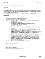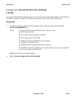
ODBE to control the diagnostic retry. The name of the global parameter is GLRETRY. The default value for
GLRETRY is 2, which will produce the same results for the retry as described in the previous sections. If GLRETRY
is changed to 1, the first failure message and the STF RETRY TO FOLLOW message will be silenced. In this mode,
the output of the diagnostic retry will be unseen by the craft. If GLRETRY is modified to 0, the diagnostic retry will be
completely turned off.
12.3 REX SCHEDULING
Each module has its own REX schedule. A schedule is defined as the start time and duration for each test type
along with a verbose option flag. The REX schedule is resident in the office dependent data (ODD) data base, and
can be changed and/or displayed via recent change/verify (RCV) mechanisms. The REX program obtains the
schedule, from the ODD relation ``rlRXSCHD'', for the current day at midnight. Therefore, if the REX schedule is
modified, the new schedule is not effective until the midnight following the change.
REX also provides the ability to turn off the REX scheduling without modifying the data base. This can be done by
putting a module test type in an inhibit state via the
INH:REX
command. The inhibit state remains active until it is
removed via the
ALW:REX
command. The inhibit status is printed automatically at midnight so that the craft can
keep track of what modules have been inhibited or what modules have individual units inhibited for test.
In the AM, REX is scheduled and initiated by the CRON process in the
UNIX
®
RTR. The schedule is set in
/user/lib/crontab
file. Refer to 235-700-200,
UNIX
®
System Reference Manual
for the details of the system CRON
file and the man pages for cron and crontab.
Two CM models are available as part of the 5ESS-2000 switch architecture: communication module, model 1 (CM1)
for configurations up to 48 SMs/SM-2000s, and communication module, model 2 (CM2) for configurations up to 192
SMs/SM-2000s. For the CM, REX schedules full diagnostics for the message switch (MSGS) and the ONTC.
Growable units, that is, module message processors (MMPs) are scheduled as they became fully operational in the
ODD data base.
In both CM1 and CM2, the MSGS consists of the message switch control unit (MSCU), the CMP, the PPC, the FPC,
and the MMPs. For 5E9(2) and later software releases, CM2 may have optional QLPS Gateway Processor (QGP) in
the MSGS. For CM1, the ONTC consists of the link interface (LI), the network clock (NC), the message interface
(MI), the time multiplexed switch (TMS), and the dual link interfaces (DLIs).
For 5E9(2) and later software releases, CM2 may have optional QLPS in the ONTC. If equipped with SM-2000, NLIs
are used instead of DLIs. In the CM2 ONTC, the dual message interface (DMI) replaces both the MI and LI to
account for both the dual and single fabric configurations of the TMS. The role of the NC, TMS, and DLIs remains
the same in CM2 as in CM1.
In the SMs/SM-2000s, the module controller/time slot interchanger (MCTSI) and its associated peripheral units are
scheduled for full diagnostics. The number and types of peripheral units scheduled are based on how the
SM/SM-2000 is equipped.
12.4 REX MANUAL COMMANDS
12.4.1 EXECUTE
The execute command will initiate routine exercise scheduling for the entire office, a single module, and/or a single
test type. If a test type is currently executing or is inhibited, the request will be ignored. A message signaling that
REX has started will be printed after all operational units have been tallied and placed in the not started column of
the REX summary report. See Procedure 13.1 for complete command syntax and Procedure 13.2 to analyze the
resulting output message. (There is no manual execution for REX in the AM.)
12.4.2 VERBOSE OPTION
235-105-210
October 1999
Copyright © 1999
Page 3
Содержание 5ESS-2000
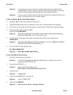
Страница 96: ...235 105 210 October 1999 Copyright 1999 Page 2 ...
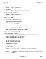
Страница 184: ...235 105 210 October 1999 Copyright 1999 Page 3 ...
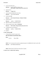
Страница 300: ...13 STOP YOU HAVE COMPLETED THIS PROCEDURE 235 105 210 October 1999 Copyright 1999 Page 55 ...
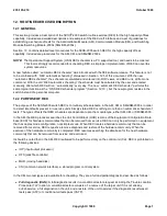
Страница 339: ...7 STOP YOU HAVE COMPLETED THIS PROCEDURE 235 105 210 October 1999 Copyright 1999 Page 13 ...
Страница 342: ...235 105 210 October 1999 Copyright 1999 Page 2 ...
Страница 359: ...235 105 210 October 1999 Copyright 1999 Page 5 ...
Страница 516: ...Figure 10 24 1 KS 23483 L13 Disk Drive Cable Connection Rear View 235 105 210 October 1999 Copyright 1999 Page 2 ...
Страница 517: ...Figure 10 24 2 KS 23483 L21 Disk Drive Cable Connection Rear View 235 105 210 October 1999 Copyright 1999 Page 3 ...
Страница 518: ...Figure 10 24 3 KS 23841 L15 Disk Drive Cable Connection Rear View 235 105 210 October 1999 Copyright 1999 Page 4 ...
Страница 523: ...Figure 10 24 6 Top View of DUP Showing Internal Cabling 235 105 210 October 1999 Copyright 1999 Page 9 ...
Страница 609: ...2 STOP YOU HAVE COMPLETED THIS PROCEDURE 235 105 210 October 1999 Copyright 1999 Page 12 ...
Страница 628: ...a SM inhibited Response OK 2 STOP YOU HAVE COMPLETED THIS PROCEDURE 235 105 210 October 1999 Copyright 1999 Page 8 ...
Страница 653: ...Response OK 2 STOP YOU HAVE COMPLETED THIS PROCEDURE 235 105 210 October 1999 Copyright 1999 Page 16 ...
Страница 676: ...235 105 210 October 1999 Copyright 1999 Page 9 ...
Страница 792: ...3 STOP YOU HAVE COMPLETED THIS PROCEDURE 235 105 210 October 1999 Copyright 1999 Page 9 ...
Страница 799: ...Figure 11 36 3 1 Cleaning Points 235 105 210 October 1999 Copyright 1999 Page 7 ...
Страница 801: ...235 105 210 October 1999 Copyright 1999 Page 9 ...
Страница 839: ...2 STOP YOU HAVE COMPLETED THIS PROCEDURE 235 105 210 October 1999 Copyright 1999 Page 16 ...
Страница 999: ...2 STOP YOU HAVE COMPLETED THIS PROCEDURE 235 105 210 October 1999 Copyright 1999 Page 13 ...
Страница 1008: ...Figure 11 55 1 CTSNS DIP Switch Settings 235 105 210 October 1999 Copyright 1999 Page 2 ...
Страница 1011: ...235 105 210 October 1999 Copyright 1999 Page 5 ...
Страница 1053: ...235 105 210 October 1999 Copyright 1999 Page 15 ...
Страница 1165: ...Procedure 14 14 RESERVED FOR FUTURE USE PROCEDURE 1 Reserved For future use 235 105 210 October 1999 Copyright 1999 Page 1 ...
Страница 1186: ...Procedure 14 17 RESERVED FOR FUTURE USE PROCEDURE 1 Reserved For future use 235 105 210 October 1999 Copyright 1999 Page 1 ...
Страница 1187: ...Procedure 14 18 RESERVED FOR FUTURE USE PROCEDURE 1 Reserved For future use 235 105 210 October 1999 Copyright 1999 Page 1 ...
Страница 1284: ...Figure 15 15 1 PARADYNE Paradyne Corporation 3810 Modem Diagnostic Control Panel 235 105 210 October 1999 Copyright 1999 Page 6 ...
Страница 1287: ...Figure 15 16 1 153A Adapter Connection Figure 15 16 2 AMATPS Block Diagram 235 105 210 October 1999 Copyright 1999 Page 3 ...
Страница 1289: ...Figure 15 17 2 AMATPS Data Link 235 105 210 October 1999 Copyright 1999 Page 2 ...
Страница 1290: ...Figure 15 17 3 Single Housing B25A Cable Assembly 235 105 210 October 1999 Copyright 1999 Page 3 ...
Страница 1292: ...235 105 210 October 1999 Copyright 1999 Page 5 ...
Страница 1294: ...Figure 15 17 8 201C to TN82 Data Set Cable Drawing 235 105 210 October 1999 Copyright 1999 Page 7 ...
Страница 1303: ...9 STOP YOU HAVE COMPLETED THIS PROCEDURE 235 105 210 October 1999 Copyright 1999 Page 2 ...
Страница 1324: ...11 Type and enter q 12 STOP YOU HAVE COMPLETED THIS PROCEDURE 235 105 210 October 1999 Copyright 1999 Page 2 ...
Страница 1342: ...Figure 15 40 1 SCANS II Dial Up Data Set Installation Diagram 235 105 210 October 1999 Copyright 1999 Page 2 ...
Страница 1344: ...Figure 15 40 4 59A1 Mounting Front in Slot J3 Figure 15 40 5 2048A Data Set Front 235 105 210 October 1999 Copyright 1999 Page 4 ...
Страница 1345: ...Figure 15 40 6 Berg Connector Terminations and Layout 235 105 210 October 1999 Copyright 1999 Page 5 ...
Страница 1346: ...Figure 15 40 7 B25A Cable 4 STOP YOU HAVE COMPLETED THIS PROCEDURE 235 105 210 October 1999 Copyright 1999 Page 6 ...
Страница 1360: ...Figure 15 47 2 Typical SCANS III Link Diagram 235 105 210 October 1999 Copyright 1999 Page 2 ...
Страница 1368: ...Response FA or OK appears 17 STOP YOU HAVE COMPLETED THIS PROCEDURE 235 105 210 October 1999 Copyright 1999 Page 2 ...
Страница 1372: ...235 105 210 October 1999 Copyright 1999 Page 2 ...
Страница 1374: ...235 105 210 October 1999 Copyright 1999 Page 4 ...
Страница 1376: ...Figure 15 55 6 201C to TN83 Data Set Cable Drawing 235 105 210 October 1999 Copyright 1999 Page 6 ...
Страница 1418: ...Figure 15 56 1 PARADYNE 3810 Modem Diagnostic Control Panel 235 105 210 October 1999 Copyright 1999 Page 4 ...
Страница 1421: ...Table 1 1 O M Checklist 235 105 210 October 1999 Copyright 1999 Page 3 ...

