alternative (manual methods of loading or backing out SUs).
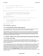
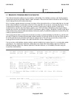
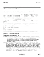
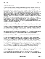
The craft can install a software update through the use of the software update installation menu (Figure 5-5 ). This
menu is on MCC Page 1960. The craft interface simplifies the task of installing a software update by directing the
craft through the installation process. The upper part of the display provides a list of menu items, each of which is
identified by a poke number. The lower part of the menu page provides a display window for sections of the
message file. The current section of the message file, called the working section, is displayed so it may be
examined by the craft before execution. If the working section does not fit in the designated window, the craft can
scroll forward and backward using the NEXT and PREVIOUS window pokes. The message file may be printed on
the MCC printer by entering the PRINT poke provided on the menu page. A RESPONSE line is provided on the
software update installation page to provide response messages to the craft during software update installation.
Sequencing checks are made between software updates to ensure proper sequencing for all software updates in a
5ESS-2000 switch.
To select a particular software update, the START software update poke is entered along with the desired software
update number. The menu page then displays the current status of the requested software update and sets the
``BWM='' indicator to the requested software update name. The VERIFY poke automatically deletes messages from
the message file which are not in the language format required for the specific office. Additionally, this poke checks
the message file integrity. The VERIFY poke must be executed before the software update can be applied to the
system. When this poke is completed successfully, an indicator is provided on the display to notify the craft that the
software update was successfully verified. The VERIFY poke may be executed as many times as desired. However,
if there was no change to the message file since the last VERIFY poke was executed and the VERIFY flag is set to
COMPLETED, subsequent VERIFY commands are rejected. When the software update has been successfully
verified, the contents of the APPLY section of the message file are automatically displayed. The action indicators
(DISPLAY, PRINT, EXEC ALL, and EXEC NEXT) are then used in conjunction with the section indicators (APPLY,
SOAK, OFC, BKOUT, and FILE) to perform the desired software update installation functions. A single poke number
is used to represent the action desired and the section of the message file to be acted upon. The first two digits
represent the action, and the second two digits represent the section.
To apply the selected software update, the 9310 poke (EXEC ALL, APPLY) is used. This poke causes all
commands in the APPLY section of the message file to be executed automatically and in sequential order. These
commands may be executed one at a time using the 9410 (EXEC NEXT, APPLY) poke. The 9410 poke must be
used repetitively to execute all the commands in the APPLY section. The 9310 poke may be used at any time after a
9410 poke in order to cause the execution of all remaining command lines in the APPLY section of the message file.
Subsequent to an EXEC poke, the RESET LINE poke may be used to reset the current command to be executed.
This poke is entered followed by a comma and a line number to which the execution pointer should be reset. The
specified line is then highlighted and may be executed again. If the requested line number is in the next or previous
display window, the RESET LINE poke causes the display window to be adjusted.
If an error occurs during the execution of a command line, a summary of the error is displayed on the RESPONSE
line of the menu page. The command line causing the error is displayed, and a detailed error message is printed on
the MCC printer. If the 9310 poke is being used when the error occurs, execution of the next command line (if any
are still remaining) is automatically stopped.
The STOP EXEC poke (9560) may be used subsequent to the EXEC ALL poke to stop execution of the next
command line in the section.
Updates intended for switching modules are automatically propagated to all operational switching modules. Any
switching modules which are isolated at the time of the update do not get updated. When all command lines in the
section are successfully executed, a ``CMPL'' indicator associated with the APPLY status is displayed, and the
content of the SOAK section is automatically displayed. This guides the user to the next step of the software update
installation process. This section of the message file contains the procedures required to test the software update
and the required soak interval.
235-105-210
October 1999
Copyright © 1999
Page 13
Содержание 5ESS-2000
Страница 96: ...235 105 210 October 1999 Copyright 1999 Page 2 ...
Страница 184: ...235 105 210 October 1999 Copyright 1999 Page 3 ...
Страница 300: ...13 STOP YOU HAVE COMPLETED THIS PROCEDURE 235 105 210 October 1999 Copyright 1999 Page 55 ...
Страница 339: ...7 STOP YOU HAVE COMPLETED THIS PROCEDURE 235 105 210 October 1999 Copyright 1999 Page 13 ...
Страница 342: ...235 105 210 October 1999 Copyright 1999 Page 2 ...
Страница 359: ...235 105 210 October 1999 Copyright 1999 Page 5 ...
Страница 516: ...Figure 10 24 1 KS 23483 L13 Disk Drive Cable Connection Rear View 235 105 210 October 1999 Copyright 1999 Page 2 ...
Страница 517: ...Figure 10 24 2 KS 23483 L21 Disk Drive Cable Connection Rear View 235 105 210 October 1999 Copyright 1999 Page 3 ...
Страница 518: ...Figure 10 24 3 KS 23841 L15 Disk Drive Cable Connection Rear View 235 105 210 October 1999 Copyright 1999 Page 4 ...
Страница 523: ...Figure 10 24 6 Top View of DUP Showing Internal Cabling 235 105 210 October 1999 Copyright 1999 Page 9 ...
Страница 609: ...2 STOP YOU HAVE COMPLETED THIS PROCEDURE 235 105 210 October 1999 Copyright 1999 Page 12 ...
Страница 628: ...a SM inhibited Response OK 2 STOP YOU HAVE COMPLETED THIS PROCEDURE 235 105 210 October 1999 Copyright 1999 Page 8 ...
Страница 653: ...Response OK 2 STOP YOU HAVE COMPLETED THIS PROCEDURE 235 105 210 October 1999 Copyright 1999 Page 16 ...
Страница 676: ...235 105 210 October 1999 Copyright 1999 Page 9 ...
Страница 792: ...3 STOP YOU HAVE COMPLETED THIS PROCEDURE 235 105 210 October 1999 Copyright 1999 Page 9 ...
Страница 799: ...Figure 11 36 3 1 Cleaning Points 235 105 210 October 1999 Copyright 1999 Page 7 ...
Страница 801: ...235 105 210 October 1999 Copyright 1999 Page 9 ...
Страница 839: ...2 STOP YOU HAVE COMPLETED THIS PROCEDURE 235 105 210 October 1999 Copyright 1999 Page 16 ...
Страница 999: ...2 STOP YOU HAVE COMPLETED THIS PROCEDURE 235 105 210 October 1999 Copyright 1999 Page 13 ...
Страница 1008: ...Figure 11 55 1 CTSNS DIP Switch Settings 235 105 210 October 1999 Copyright 1999 Page 2 ...
Страница 1011: ...235 105 210 October 1999 Copyright 1999 Page 5 ...
Страница 1053: ...235 105 210 October 1999 Copyright 1999 Page 15 ...
Страница 1165: ...Procedure 14 14 RESERVED FOR FUTURE USE PROCEDURE 1 Reserved For future use 235 105 210 October 1999 Copyright 1999 Page 1 ...
Страница 1186: ...Procedure 14 17 RESERVED FOR FUTURE USE PROCEDURE 1 Reserved For future use 235 105 210 October 1999 Copyright 1999 Page 1 ...
Страница 1187: ...Procedure 14 18 RESERVED FOR FUTURE USE PROCEDURE 1 Reserved For future use 235 105 210 October 1999 Copyright 1999 Page 1 ...
Страница 1284: ...Figure 15 15 1 PARADYNE Paradyne Corporation 3810 Modem Diagnostic Control Panel 235 105 210 October 1999 Copyright 1999 Page 6 ...
Страница 1287: ...Figure 15 16 1 153A Adapter Connection Figure 15 16 2 AMATPS Block Diagram 235 105 210 October 1999 Copyright 1999 Page 3 ...
Страница 1289: ...Figure 15 17 2 AMATPS Data Link 235 105 210 October 1999 Copyright 1999 Page 2 ...
Страница 1290: ...Figure 15 17 3 Single Housing B25A Cable Assembly 235 105 210 October 1999 Copyright 1999 Page 3 ...
Страница 1292: ...235 105 210 October 1999 Copyright 1999 Page 5 ...
Страница 1294: ...Figure 15 17 8 201C to TN82 Data Set Cable Drawing 235 105 210 October 1999 Copyright 1999 Page 7 ...
Страница 1303: ...9 STOP YOU HAVE COMPLETED THIS PROCEDURE 235 105 210 October 1999 Copyright 1999 Page 2 ...
Страница 1324: ...11 Type and enter q 12 STOP YOU HAVE COMPLETED THIS PROCEDURE 235 105 210 October 1999 Copyright 1999 Page 2 ...
Страница 1342: ...Figure 15 40 1 SCANS II Dial Up Data Set Installation Diagram 235 105 210 October 1999 Copyright 1999 Page 2 ...
Страница 1344: ...Figure 15 40 4 59A1 Mounting Front in Slot J3 Figure 15 40 5 2048A Data Set Front 235 105 210 October 1999 Copyright 1999 Page 4 ...
Страница 1345: ...Figure 15 40 6 Berg Connector Terminations and Layout 235 105 210 October 1999 Copyright 1999 Page 5 ...
Страница 1346: ...Figure 15 40 7 B25A Cable 4 STOP YOU HAVE COMPLETED THIS PROCEDURE 235 105 210 October 1999 Copyright 1999 Page 6 ...
Страница 1360: ...Figure 15 47 2 Typical SCANS III Link Diagram 235 105 210 October 1999 Copyright 1999 Page 2 ...
Страница 1368: ...Response FA or OK appears 17 STOP YOU HAVE COMPLETED THIS PROCEDURE 235 105 210 October 1999 Copyright 1999 Page 2 ...
Страница 1372: ...235 105 210 October 1999 Copyright 1999 Page 2 ...
Страница 1374: ...235 105 210 October 1999 Copyright 1999 Page 4 ...
Страница 1376: ...Figure 15 55 6 201C to TN83 Data Set Cable Drawing 235 105 210 October 1999 Copyright 1999 Page 6 ...
Страница 1418: ...Figure 15 56 1 PARADYNE 3810 Modem Diagnostic Control Panel 235 105 210 October 1999 Copyright 1999 Page 4 ...
Страница 1421: ...Table 1 1 O M Checklist 235 105 210 October 1999 Copyright 1999 Page 3 ...

