10
-
170
160
11
-
187
176
12
-
200 (max)
a
192 (max)
Notes:
a.
The maximum number of ACD/OSPS positions per SM is 200.
11.6.2.2 SPROSPS CD Configuration
1.
The host SM does not allocate time slots (24 per facility) to the spare facility of an ACD/OSPS RISLU. After
the conversion, however, the spare facility will require time slots, as it will be made active. For example, if the
ACD/OSPS RISLU currently has 5 facilities (including one spare), in the TSIU of the host SM, 96 time slots
are assigned to the RISLU. After the conversion, 120 time slots are required to support the 5 active facilities
in the ERISLU. The 24 time slots allocated will be counted against the TSIU time slot total. If the TSIU time
slot total is exhausted for any other reason, reengineering of the PSU TSIU time slot and/or the RISLU is
required or call blocking will result.
11.6.2.3 DFI-Hs Stuffing Patterns
1.
The DFI-Hs stuffing patterns are assigned by the system during the conversion update of CD configuration
and DFI mode (RC/V 22.9). The assignment will be based on existing distribution of patterns of DFIs
connected to the converting RISLU's DI. The spare DFI-H of the SPROSPS RISLU, however, does not
require reserved pattern prior to the conversion, and when made active, could result in RC/V 22.9 update
failure due to lack of available time slots for any valid pattern. In this case, the spare DFI-H must be
unassigned, or the TSIU time slot distribution must be reengineered.
11.6.2.4 TSIU Peripheral Side Considerations
1.
ACD/OSPS positions D-channel (one per position) traffic is routed to the Packet Switch Unit (PSU) across the
32-time-slot Peripheral Interface Data Bus (PIDB). Each D-channel is a 16-kb/s channel. Four D-channels
can be multiplexed by the RISLU onto a single time slot (TS); however, RISLUs which have been remoted via
non-clear channel (ZCS) facilities do not have the full use of the 64-kb/s DS0 channel. For non-clear channel
facility, the RISLU multiplexes 3 D-channels per time slot.
If the current (preconversion) transmission mode for the DFI facilities is FE, thus requiring ZCS as the new
DFI mode, additional reserved DI PSU TSIU TSs, or reassignment of existing ACD/OSPS positions, may be
necessary prior to the ACD/OSPS RISLU to ERISLU conversion.
The RISLU's LCs and their relations to the PSU PIDB can be found under RC/V view 22.19 (STATUS OF
PSU PIDBs FOR RISLU ASSIGNMENT).
11.6.2.5 Assignment of Additional DI PSU TSIU Time Slots
1.
Moving a port(s) from one full time slot to an empty time slot would also require that the number of reserved
time slots (nail up) to the connecting DI is sufficient to handle the additional nail up.
The assignment of additional reserved DI PSU TSIU time slots is the customer's responsibility and can be
performed using RC/V 22.2 for field DI0 PSU TSIU TIMESLOTS or DI1 PSU TSIU TIMESLOTS, respectively.
DI number [0-1] must be the same for all ACD/OSPS RISLU DFIs and is populated under the DI field of RC/V
view 22.9.
11.6.2.6 PSU PIDB Considerations
1.
This section is applicable only when the current DFI MODE is FE [indicating that current facility has 56 Kbps
(non-clear) hardware mode]. The predictability of OSPS traffic combined with special OSPS position set
hardware allowed the use of four quarter time slot with minimum retransmission due to bad frames. However,
235-105-210
October 1999
Copyright © 1999
Page 3
Содержание 5ESS-2000
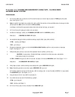
Страница 96: ...235 105 210 October 1999 Copyright 1999 Page 2 ...
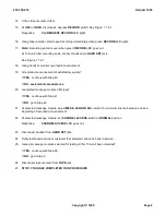
Страница 184: ...235 105 210 October 1999 Copyright 1999 Page 3 ...
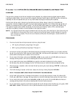
Страница 300: ...13 STOP YOU HAVE COMPLETED THIS PROCEDURE 235 105 210 October 1999 Copyright 1999 Page 55 ...
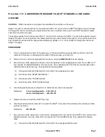
Страница 339: ...7 STOP YOU HAVE COMPLETED THIS PROCEDURE 235 105 210 October 1999 Copyright 1999 Page 13 ...
Страница 342: ...235 105 210 October 1999 Copyright 1999 Page 2 ...
Страница 359: ...235 105 210 October 1999 Copyright 1999 Page 5 ...
Страница 516: ...Figure 10 24 1 KS 23483 L13 Disk Drive Cable Connection Rear View 235 105 210 October 1999 Copyright 1999 Page 2 ...
Страница 517: ...Figure 10 24 2 KS 23483 L21 Disk Drive Cable Connection Rear View 235 105 210 October 1999 Copyright 1999 Page 3 ...
Страница 518: ...Figure 10 24 3 KS 23841 L15 Disk Drive Cable Connection Rear View 235 105 210 October 1999 Copyright 1999 Page 4 ...
Страница 523: ...Figure 10 24 6 Top View of DUP Showing Internal Cabling 235 105 210 October 1999 Copyright 1999 Page 9 ...
Страница 609: ...2 STOP YOU HAVE COMPLETED THIS PROCEDURE 235 105 210 October 1999 Copyright 1999 Page 12 ...
Страница 628: ...a SM inhibited Response OK 2 STOP YOU HAVE COMPLETED THIS PROCEDURE 235 105 210 October 1999 Copyright 1999 Page 8 ...
Страница 653: ...Response OK 2 STOP YOU HAVE COMPLETED THIS PROCEDURE 235 105 210 October 1999 Copyright 1999 Page 16 ...
Страница 676: ...235 105 210 October 1999 Copyright 1999 Page 9 ...
Страница 792: ...3 STOP YOU HAVE COMPLETED THIS PROCEDURE 235 105 210 October 1999 Copyright 1999 Page 9 ...
Страница 799: ...Figure 11 36 3 1 Cleaning Points 235 105 210 October 1999 Copyright 1999 Page 7 ...
Страница 801: ...235 105 210 October 1999 Copyright 1999 Page 9 ...
Страница 839: ...2 STOP YOU HAVE COMPLETED THIS PROCEDURE 235 105 210 October 1999 Copyright 1999 Page 16 ...
Страница 999: ...2 STOP YOU HAVE COMPLETED THIS PROCEDURE 235 105 210 October 1999 Copyright 1999 Page 13 ...
Страница 1008: ...Figure 11 55 1 CTSNS DIP Switch Settings 235 105 210 October 1999 Copyright 1999 Page 2 ...
Страница 1011: ...235 105 210 October 1999 Copyright 1999 Page 5 ...
Страница 1053: ...235 105 210 October 1999 Copyright 1999 Page 15 ...
Страница 1165: ...Procedure 14 14 RESERVED FOR FUTURE USE PROCEDURE 1 Reserved For future use 235 105 210 October 1999 Copyright 1999 Page 1 ...
Страница 1186: ...Procedure 14 17 RESERVED FOR FUTURE USE PROCEDURE 1 Reserved For future use 235 105 210 October 1999 Copyright 1999 Page 1 ...
Страница 1187: ...Procedure 14 18 RESERVED FOR FUTURE USE PROCEDURE 1 Reserved For future use 235 105 210 October 1999 Copyright 1999 Page 1 ...
Страница 1284: ...Figure 15 15 1 PARADYNE Paradyne Corporation 3810 Modem Diagnostic Control Panel 235 105 210 October 1999 Copyright 1999 Page 6 ...
Страница 1287: ...Figure 15 16 1 153A Adapter Connection Figure 15 16 2 AMATPS Block Diagram 235 105 210 October 1999 Copyright 1999 Page 3 ...
Страница 1289: ...Figure 15 17 2 AMATPS Data Link 235 105 210 October 1999 Copyright 1999 Page 2 ...
Страница 1290: ...Figure 15 17 3 Single Housing B25A Cable Assembly 235 105 210 October 1999 Copyright 1999 Page 3 ...
Страница 1292: ...235 105 210 October 1999 Copyright 1999 Page 5 ...
Страница 1294: ...Figure 15 17 8 201C to TN82 Data Set Cable Drawing 235 105 210 October 1999 Copyright 1999 Page 7 ...
Страница 1303: ...9 STOP YOU HAVE COMPLETED THIS PROCEDURE 235 105 210 October 1999 Copyright 1999 Page 2 ...
Страница 1324: ...11 Type and enter q 12 STOP YOU HAVE COMPLETED THIS PROCEDURE 235 105 210 October 1999 Copyright 1999 Page 2 ...
Страница 1342: ...Figure 15 40 1 SCANS II Dial Up Data Set Installation Diagram 235 105 210 October 1999 Copyright 1999 Page 2 ...
Страница 1344: ...Figure 15 40 4 59A1 Mounting Front in Slot J3 Figure 15 40 5 2048A Data Set Front 235 105 210 October 1999 Copyright 1999 Page 4 ...
Страница 1345: ...Figure 15 40 6 Berg Connector Terminations and Layout 235 105 210 October 1999 Copyright 1999 Page 5 ...
Страница 1346: ...Figure 15 40 7 B25A Cable 4 STOP YOU HAVE COMPLETED THIS PROCEDURE 235 105 210 October 1999 Copyright 1999 Page 6 ...
Страница 1360: ...Figure 15 47 2 Typical SCANS III Link Diagram 235 105 210 October 1999 Copyright 1999 Page 2 ...
Страница 1368: ...Response FA or OK appears 17 STOP YOU HAVE COMPLETED THIS PROCEDURE 235 105 210 October 1999 Copyright 1999 Page 2 ...
Страница 1372: ...235 105 210 October 1999 Copyright 1999 Page 2 ...
Страница 1374: ...235 105 210 October 1999 Copyright 1999 Page 4 ...
Страница 1376: ...Figure 15 55 6 201C to TN83 Data Set Cable Drawing 235 105 210 October 1999 Copyright 1999 Page 6 ...
Страница 1418: ...Figure 15 56 1 PARADYNE 3810 Modem Diagnostic Control Panel 235 105 210 October 1999 Copyright 1999 Page 4 ...
Страница 1421: ...Table 1 1 O M Checklist 235 105 210 October 1999 Copyright 1999 Page 3 ...

