


Growth
is a hardware procedure that adds an additional disk, or disk pair, to an existing office.
Growth
includes
addition of SCSI frames and disks for preparation of a retrofit.
Conversion
is a procedure that replaces one type of disk hardware with a newer type.
Retrofit
is a procedure that replaces an existing software release with a later software release or a newer version of
the existing software release. Refer to the 235-105-24X series of release specific retrofit manuals for 5E9(2) and
earlier. Refer to the 235-106-10X series for 5E10.
Reconfiguration
is a procedure that replaces the current disk configuration with a disk configuration that has more
system storage capacity, for example, 63 to 66.
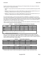
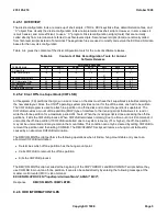
The disk reconfigurations that are possible are as follows:
DISK RECONFIGURATION SUPPORTED BY THE 5E9 AND LATER SOFTWARE RELEASES
CURRENT NEW BASE DISK CONFIGURATION
BASE DISK
CONFIGURATION 63 66
63 o x
66 o
Where:
o = Reconfiguration of optional disks (Base remains the same).
x = Reconfiguration of base disks (and optional disks).
New start offices that run on the 3B21D processor come with 1GB base pair disk drives that are formatted with 1GB
VTOCs. For the 5E10 release, only optional disk pairs may be reconfigured when running on the 3B21D processor.
9.2.2 DISK RECONFIGURATION OVERVIEW
From a very high-level view, disk reconfiguration has some of the following characteristics of software release
retrofit:
The disks are divided into an on-line system (composed of the even-numbered disks) and an off-line system
(composed of the odd-numbered disks).
A new disk configuration is built on the off-line disk system.
The system is booted onto the new disk configuration.
After some system sanity tests are performed, the disks are duplexed.
If any of the sanity tests fail, the system is booted back onto the original disk configuration.
The major difference between software release retrofit and disk reconfiguration is the amount of new data that is
brought into the office. The only new data required for a disk reconfiguration are the volume table of contents
(VTOC) files for the new disk configuration. The new equipment configuration data base (ECD) and system
generation (SG) data bases are evolved from the existing data bases on the switch. The ODD and other data for the
new disk configuration are copied from the old disk configuration.
The disk reconfiguration procedure is designed to be completed in a single 8-hour shift. During this shift, all recent
changes (RC) must be blocked. All persons that regularly install RCs must be notified in advance of the disk
reconfiguration procedure.
235-105-210
October 1999
Copyright © 1999
Page 3
Содержание 5ESS-2000
Страница 96: ...235 105 210 October 1999 Copyright 1999 Page 2 ...
Страница 184: ...235 105 210 October 1999 Copyright 1999 Page 3 ...
Страница 300: ...13 STOP YOU HAVE COMPLETED THIS PROCEDURE 235 105 210 October 1999 Copyright 1999 Page 55 ...
Страница 339: ...7 STOP YOU HAVE COMPLETED THIS PROCEDURE 235 105 210 October 1999 Copyright 1999 Page 13 ...
Страница 342: ...235 105 210 October 1999 Copyright 1999 Page 2 ...
Страница 359: ...235 105 210 October 1999 Copyright 1999 Page 5 ...
Страница 516: ...Figure 10 24 1 KS 23483 L13 Disk Drive Cable Connection Rear View 235 105 210 October 1999 Copyright 1999 Page 2 ...
Страница 517: ...Figure 10 24 2 KS 23483 L21 Disk Drive Cable Connection Rear View 235 105 210 October 1999 Copyright 1999 Page 3 ...
Страница 518: ...Figure 10 24 3 KS 23841 L15 Disk Drive Cable Connection Rear View 235 105 210 October 1999 Copyright 1999 Page 4 ...
Страница 523: ...Figure 10 24 6 Top View of DUP Showing Internal Cabling 235 105 210 October 1999 Copyright 1999 Page 9 ...
Страница 609: ...2 STOP YOU HAVE COMPLETED THIS PROCEDURE 235 105 210 October 1999 Copyright 1999 Page 12 ...
Страница 628: ...a SM inhibited Response OK 2 STOP YOU HAVE COMPLETED THIS PROCEDURE 235 105 210 October 1999 Copyright 1999 Page 8 ...
Страница 653: ...Response OK 2 STOP YOU HAVE COMPLETED THIS PROCEDURE 235 105 210 October 1999 Copyright 1999 Page 16 ...
Страница 676: ...235 105 210 October 1999 Copyright 1999 Page 9 ...
Страница 792: ...3 STOP YOU HAVE COMPLETED THIS PROCEDURE 235 105 210 October 1999 Copyright 1999 Page 9 ...
Страница 799: ...Figure 11 36 3 1 Cleaning Points 235 105 210 October 1999 Copyright 1999 Page 7 ...
Страница 801: ...235 105 210 October 1999 Copyright 1999 Page 9 ...
Страница 839: ...2 STOP YOU HAVE COMPLETED THIS PROCEDURE 235 105 210 October 1999 Copyright 1999 Page 16 ...
Страница 999: ...2 STOP YOU HAVE COMPLETED THIS PROCEDURE 235 105 210 October 1999 Copyright 1999 Page 13 ...
Страница 1008: ...Figure 11 55 1 CTSNS DIP Switch Settings 235 105 210 October 1999 Copyright 1999 Page 2 ...
Страница 1011: ...235 105 210 October 1999 Copyright 1999 Page 5 ...
Страница 1053: ...235 105 210 October 1999 Copyright 1999 Page 15 ...
Страница 1165: ...Procedure 14 14 RESERVED FOR FUTURE USE PROCEDURE 1 Reserved For future use 235 105 210 October 1999 Copyright 1999 Page 1 ...
Страница 1186: ...Procedure 14 17 RESERVED FOR FUTURE USE PROCEDURE 1 Reserved For future use 235 105 210 October 1999 Copyright 1999 Page 1 ...
Страница 1187: ...Procedure 14 18 RESERVED FOR FUTURE USE PROCEDURE 1 Reserved For future use 235 105 210 October 1999 Copyright 1999 Page 1 ...
Страница 1284: ...Figure 15 15 1 PARADYNE Paradyne Corporation 3810 Modem Diagnostic Control Panel 235 105 210 October 1999 Copyright 1999 Page 6 ...
Страница 1287: ...Figure 15 16 1 153A Adapter Connection Figure 15 16 2 AMATPS Block Diagram 235 105 210 October 1999 Copyright 1999 Page 3 ...
Страница 1289: ...Figure 15 17 2 AMATPS Data Link 235 105 210 October 1999 Copyright 1999 Page 2 ...
Страница 1290: ...Figure 15 17 3 Single Housing B25A Cable Assembly 235 105 210 October 1999 Copyright 1999 Page 3 ...
Страница 1292: ...235 105 210 October 1999 Copyright 1999 Page 5 ...
Страница 1294: ...Figure 15 17 8 201C to TN82 Data Set Cable Drawing 235 105 210 October 1999 Copyright 1999 Page 7 ...
Страница 1303: ...9 STOP YOU HAVE COMPLETED THIS PROCEDURE 235 105 210 October 1999 Copyright 1999 Page 2 ...
Страница 1324: ...11 Type and enter q 12 STOP YOU HAVE COMPLETED THIS PROCEDURE 235 105 210 October 1999 Copyright 1999 Page 2 ...
Страница 1342: ...Figure 15 40 1 SCANS II Dial Up Data Set Installation Diagram 235 105 210 October 1999 Copyright 1999 Page 2 ...
Страница 1344: ...Figure 15 40 4 59A1 Mounting Front in Slot J3 Figure 15 40 5 2048A Data Set Front 235 105 210 October 1999 Copyright 1999 Page 4 ...
Страница 1345: ...Figure 15 40 6 Berg Connector Terminations and Layout 235 105 210 October 1999 Copyright 1999 Page 5 ...
Страница 1346: ...Figure 15 40 7 B25A Cable 4 STOP YOU HAVE COMPLETED THIS PROCEDURE 235 105 210 October 1999 Copyright 1999 Page 6 ...
Страница 1360: ...Figure 15 47 2 Typical SCANS III Link Diagram 235 105 210 October 1999 Copyright 1999 Page 2 ...
Страница 1368: ...Response FA or OK appears 17 STOP YOU HAVE COMPLETED THIS PROCEDURE 235 105 210 October 1999 Copyright 1999 Page 2 ...
Страница 1372: ...235 105 210 October 1999 Copyright 1999 Page 2 ...
Страница 1374: ...235 105 210 October 1999 Copyright 1999 Page 4 ...
Страница 1376: ...Figure 15 55 6 201C to TN83 Data Set Cable Drawing 235 105 210 October 1999 Copyright 1999 Page 6 ...
Страница 1418: ...Figure 15 56 1 PARADYNE 3810 Modem Diagnostic Control Panel 235 105 210 October 1999 Copyright 1999 Page 4 ...
Страница 1421: ...Table 1 1 O M Checklist 235 105 210 October 1999 Copyright 1999 Page 3 ...


