8-77
January 24, 2017
Structure Function Principle
CLG835H
Lighting system
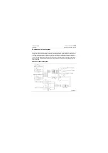
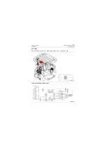
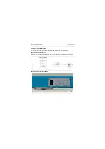
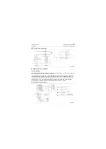
Electronic control unit
As the core of the shift control system, the elec-
tronic control unit EST125 processes and oper-
ates the signals of operator-selected gear, speed
sensor, KD and engine shutoff. Whereby,
EST125 drives the solenoid valve group combi-
nation through outputting control signals, to
implement the gear selection and shift of trans-
mission. Besides, EST125 also outputs neutral
signals, to drive the gear/neutral interlock relay to
act when the DW-3 gear selector is in neutral
position. Output the reversing alarm signal and
drive the reversing alarm relay to work.
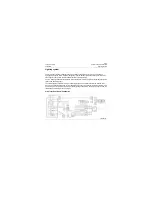
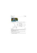
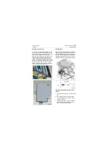
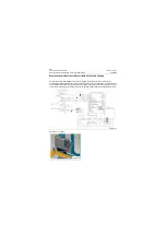
Shift selector
The internal part of a gear selector consists of
many mini switches. When the operator selects
gears and directions, the internal micro switch
works, and the changed gear and direction sig-
nals ultimately enter into the electronic control
unit EST125 through the connecting of harness.
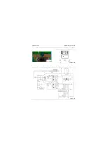
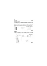
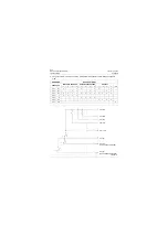
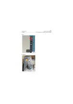
Fault detection procedures of DW-3 shift
selector
1. Turn the digital multimeter to 200
Ω
of
Ω
posi-
tion.
2. Move DW-3 gear selector to N1 position;
3. Test if only [B1, B3], [B1, AS], [B3, AS] are
pairwise energized;
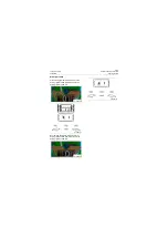
4. Shift the gear selector to other appropriate
gears, and check the parallelism in accor-
dance with the gear logic diagram;
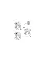
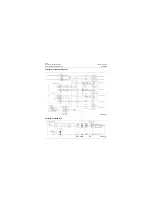
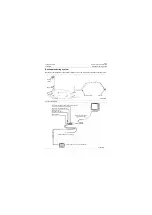
P18E00133
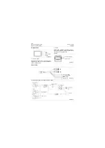
P18E00134
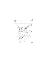
P18E00135
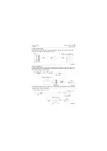
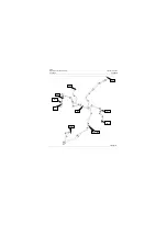
P18E00136
Gear positions
Содержание CLG835H
Страница 2: ......
Страница 4: ...Contents January 24 2017 CLG835H...
Страница 6: ...1 2 General Information January 24 2017 CLG835H...
Страница 38: ...1 34 Machine Inspection Table January 24 2017 CLG835H...
Страница 154: ...2 116 Fault Diagnosis and Troubleshooting January 24 2017 Common fault code and troubleshooting CLG835H...
Страница 156: ...3 2 Power Train System January 24 2017 CLG835H...
Страница 214: ...3 2 Power Train System January 24 2017 CLG835H...
Страница 272: ...3 60 Testing and adjustment January 24 2017 Power Train Test CLG835H...
Страница 276: ...4 4 Hydraulic System January 24 2017 CLG835H...
Страница 296: ...4 24 Structure Function Principle January 24 2017 Work hydraulic system CLG835H Exploded view of control valve P18H00016...
Страница 297: ...4 25 January 24 2017 Structure Function Principle CLG835H Work hydraulic system Exploded view of control valve P18H00017...
Страница 308: ...4 36 Structure Function Principle January 24 2017 Work hydraulic system CLG835H Outline diagram of pilot valve P18H00027...
Страница 506: ...4 234 Fault Diagnosis and Troubleshooting January 24 2017 Common troubleshooting for brake system CLG835H...
Страница 552: ...6 2 Driver s Cab System January 24 2017 CLG835H...
Страница 606: ...6 56 Removal and Installation January 24 2017 Removal and installation of the engine hood torque mechanism CLG835H...
Страница 608: ...7 2 Structure January 24 2017 CLG835H...
Страница 662: ...8 4 Electrical System January 24 2017 CLG835H...
Страница 677: ...8 19 January 24 2017 Structure Function Principle CLG835H Power System P18E00014...
Страница 737: ...8 79 January 24 2017 Structure Function Principle CLG835H Audio system Audio system Audio system principle P18E00138...
Страница 756: ...9 2 Appendix January 24 2017 CLG835H...
Страница 757: ...9 3 January 24 2017 Schematic Diagram of Hydraulic System CLG835H Schematic Diagram of Hydraulic System...
Страница 758: ...9 4 January 24 2017 Schematic Diagram of Brake System CLG835H Schematic Diagram of Brake System...

