3-12
Structure Function Principle
January 24, 2017
Torque Converter - Gearbox System
CLG835H
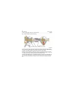
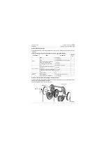
We can see from structure diagram for torque converter, a three-element, single-turbo torque converter
mainly consists of pump wheel, guide wheel and a turbine. As the pump wheel of torque converter is
directly coupled with and driven by the engine, the hydrodynamic drive oil between pump wheel and tur-
bine forms complex flow under rotation of pump wheel. The mechanical energy is converted into kinetic
energy of oil fluid. The fluid flow with kinetic energy strikes against the turbine at a high speed. The tur-
bine absorbs its kinetic energy and restores it to mechanical energy for gearbox. The guide wheel is sta-
tionary. When the fluid flow(which is from the turbine and has some kinetic energy) passes through the
curved blade of the guide wheel, the torque formed by the impact force and counterforce produced on
the blade acts on the engine base, and equivalent to the sum of increased torque of turbine from coun-
terforce and reduced torque of pump wheel from impact force. It is possible that the output torque of tur-
bine is greater than input torque of pump wheel, based on which, the torque converter is variable.
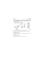
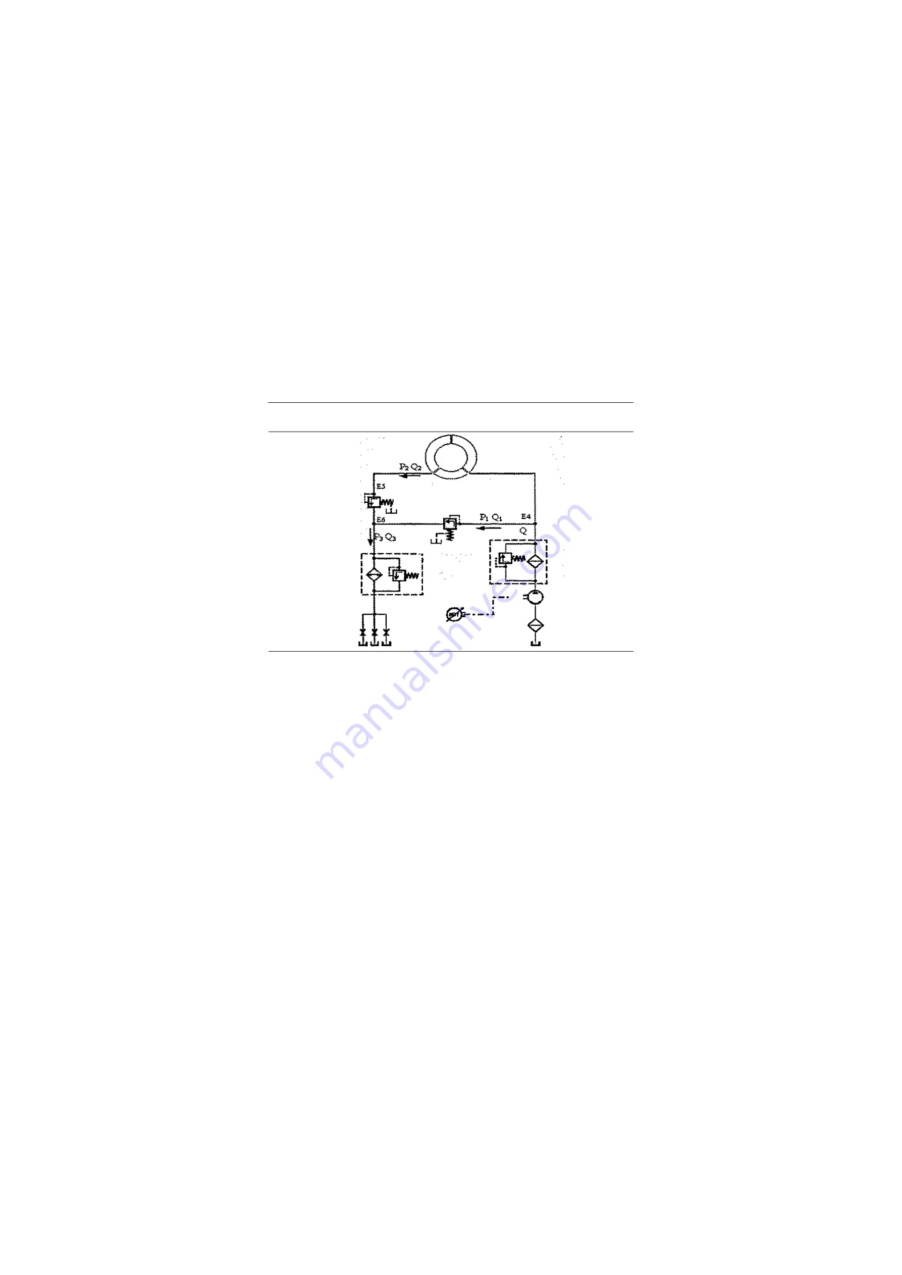
The working oil of torque converter is imported into the torque converter through the coarse and fine fil-
ters from the oil tank by the variable pump. There is a constant pressure valve (safety valve) set at the
inlet of torque converter, whose main role is to avoid excessive pressure in the torque converter to dam-
age the parts. There is another constant pressure valve (back pressure valve) at the outlet of torque con-
verter, whose main role is to ensure the torque converter is full of working oil in order to avoid cavitation
appeared during operation and impact on the performance of torque converter.
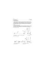
Figure 3-10Schematic diagram for torque converter hydraulic
Hydraulic torque converter
Outlet constant
pressure valve of
torque converter
Radiator
Rough
filtration
Tank
Engine
Transmission
—shaft lubrication
Inlet constant
pressure valve
of torque converter
refined
filtration
Front pump
P18T00010
Содержание CLG835H
Страница 2: ......
Страница 4: ...Contents January 24 2017 CLG835H...
Страница 6: ...1 2 General Information January 24 2017 CLG835H...
Страница 38: ...1 34 Machine Inspection Table January 24 2017 CLG835H...
Страница 154: ...2 116 Fault Diagnosis and Troubleshooting January 24 2017 Common fault code and troubleshooting CLG835H...
Страница 156: ...3 2 Power Train System January 24 2017 CLG835H...
Страница 214: ...3 2 Power Train System January 24 2017 CLG835H...
Страница 272: ...3 60 Testing and adjustment January 24 2017 Power Train Test CLG835H...
Страница 276: ...4 4 Hydraulic System January 24 2017 CLG835H...
Страница 296: ...4 24 Structure Function Principle January 24 2017 Work hydraulic system CLG835H Exploded view of control valve P18H00016...
Страница 297: ...4 25 January 24 2017 Structure Function Principle CLG835H Work hydraulic system Exploded view of control valve P18H00017...
Страница 308: ...4 36 Structure Function Principle January 24 2017 Work hydraulic system CLG835H Outline diagram of pilot valve P18H00027...
Страница 506: ...4 234 Fault Diagnosis and Troubleshooting January 24 2017 Common troubleshooting for brake system CLG835H...
Страница 552: ...6 2 Driver s Cab System January 24 2017 CLG835H...
Страница 606: ...6 56 Removal and Installation January 24 2017 Removal and installation of the engine hood torque mechanism CLG835H...
Страница 608: ...7 2 Structure January 24 2017 CLG835H...
Страница 662: ...8 4 Electrical System January 24 2017 CLG835H...
Страница 677: ...8 19 January 24 2017 Structure Function Principle CLG835H Power System P18E00014...
Страница 737: ...8 79 January 24 2017 Structure Function Principle CLG835H Audio system Audio system Audio system principle P18E00138...
Страница 756: ...9 2 Appendix January 24 2017 CLG835H...
Страница 757: ...9 3 January 24 2017 Schematic Diagram of Hydraulic System CLG835H Schematic Diagram of Hydraulic System...
Страница 758: ...9 4 January 24 2017 Schematic Diagram of Brake System CLG835H Schematic Diagram of Brake System...


