3-14
Structure Function Principle
January 24, 2017
Torque Converter - Gearbox System
CLG835H
The electro-hydraulic shift control valve consists
of solenoid valves M1, M2, M3, M4, M5, valve
stem and body. When the electro-hydraulic shift
control valve is operating, the fluid flow in the
valve stem oil passage is controlled by the power
of solenoid valves, which finally control the
engagement and disengagement of clutch in the
gear box, thus to make the gear box achieve
different shifts. For the power transferring line
and gear engagement with the gear box in
different gears, please see the figure of the
power transferring line for each gear as the
following figure 3-13 to 3-19.
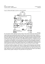
Figure 3-13 Drive line of forward gear 1
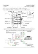
Figure 3-14 Drive line of forward gear 2
Output
shaft
Output
shaft
Input shaft
Torque
converter
turbine
P18T00013
࠰
OUT
OUT
P18T00014
࠰
࠰
Output
shaft
Output
shaft
Input shaft
Torque
converter
turbine
OUT
OUT
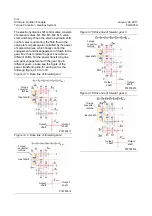
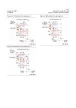
Figure 3-15 Drive line of forward gear 3
Figure 3-16 Drive line of forward gear 4
P18T00015
Output
shaft
Output
shaft
Input shaft
Torque
converter
turbine
࠰
OUT
OUT
P18T00016
Output
shaft
Output
shaft
Input shaft
Torque
converter
turbine
࠰
OUT
OUT
Содержание CLG835H
Страница 2: ......
Страница 4: ...Contents January 24 2017 CLG835H...
Страница 6: ...1 2 General Information January 24 2017 CLG835H...
Страница 38: ...1 34 Machine Inspection Table January 24 2017 CLG835H...
Страница 154: ...2 116 Fault Diagnosis and Troubleshooting January 24 2017 Common fault code and troubleshooting CLG835H...
Страница 156: ...3 2 Power Train System January 24 2017 CLG835H...
Страница 214: ...3 2 Power Train System January 24 2017 CLG835H...
Страница 272: ...3 60 Testing and adjustment January 24 2017 Power Train Test CLG835H...
Страница 276: ...4 4 Hydraulic System January 24 2017 CLG835H...
Страница 296: ...4 24 Structure Function Principle January 24 2017 Work hydraulic system CLG835H Exploded view of control valve P18H00016...
Страница 297: ...4 25 January 24 2017 Structure Function Principle CLG835H Work hydraulic system Exploded view of control valve P18H00017...
Страница 308: ...4 36 Structure Function Principle January 24 2017 Work hydraulic system CLG835H Outline diagram of pilot valve P18H00027...
Страница 506: ...4 234 Fault Diagnosis and Troubleshooting January 24 2017 Common troubleshooting for brake system CLG835H...
Страница 552: ...6 2 Driver s Cab System January 24 2017 CLG835H...
Страница 606: ...6 56 Removal and Installation January 24 2017 Removal and installation of the engine hood torque mechanism CLG835H...
Страница 608: ...7 2 Structure January 24 2017 CLG835H...
Страница 662: ...8 4 Electrical System January 24 2017 CLG835H...
Страница 677: ...8 19 January 24 2017 Structure Function Principle CLG835H Power System P18E00014...
Страница 737: ...8 79 January 24 2017 Structure Function Principle CLG835H Audio system Audio system Audio system principle P18E00138...
Страница 756: ...9 2 Appendix January 24 2017 CLG835H...
Страница 757: ...9 3 January 24 2017 Schematic Diagram of Hydraulic System CLG835H Schematic Diagram of Hydraulic System...
Страница 758: ...9 4 January 24 2017 Schematic Diagram of Brake System CLG835H Schematic Diagram of Brake System...


