4-53
January 24, 2017
Structure Function Principle
CLG835H
Brake system
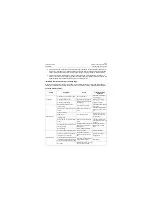
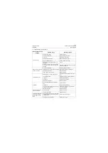
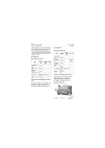
4. Troubleshooting for brake pump
Fault phenomenon of
oil pump
Possible cause
Handling method
Oil pump is noisy
Air enters the system
Tighten all joints
Oil supply is insufficient
Refill the oil to a proper level
Oil is cold
Operating in a low speed
Oil suction tube is blocked
Remove the blocking object
Air filter in tank is blocked
Clean or replace the air filter
Bad right alignment between pump and
input shaft
Check
Resonance is serious (resonance of pump
with peripheral components of oil tank and
pipeline)
Check if mounting bolts of pipeline and com-
ponents are tightened
Pump is slow at response
or has no response
Oil supply is insufficient
Refill the oil to a proper level
Setting pressure of relief valve is insufficient Readjust the pressure of relief valve
Pump is worn or broken
Repair or replace
Valve is worn or stuck or leaks
Repair or replace
Oil temperature rises
Setting pressure of relief valve is too low
Adjust the pressure or replace the relief
valve
Low viscosity of fluid
Replace with recommended hydraulic oil
Oil is dirty
Replace the hydraulic oil
Low oil level
Refill hydraulic oil properly
Pump is worn or broken
Repair or replace
Oil foaming
Air enters the system through oil suction
tube
Tighten all joints
Low oil level
Refill hydraulic oil properly
Lip type seal ring (oil seal)of main revolving
shaft is worn or damaged
Replace the lip type seal ring (oil seal)of
main revolving shaft
The flow or pressure of
pump is insufficient
Side plate is broken
Replace side plate
Relief valve fails
Replace relief valve
Air enters the system
Tighten all joints
Oil still leaks after replac-
ing the lip type seal (oil
seal)of main revolving
shaft
Worn lip type seal ring (oil seal) of revolving
shaft causes damage to the sealing area of
drive gear shaft
Replace the drive gear shaft
Seal ring is worn or damaged
Replace the seal ring
Содержание CLG835H
Страница 2: ......
Страница 4: ...Contents January 24 2017 CLG835H...
Страница 6: ...1 2 General Information January 24 2017 CLG835H...
Страница 38: ...1 34 Machine Inspection Table January 24 2017 CLG835H...
Страница 154: ...2 116 Fault Diagnosis and Troubleshooting January 24 2017 Common fault code and troubleshooting CLG835H...
Страница 156: ...3 2 Power Train System January 24 2017 CLG835H...
Страница 214: ...3 2 Power Train System January 24 2017 CLG835H...
Страница 272: ...3 60 Testing and adjustment January 24 2017 Power Train Test CLG835H...
Страница 276: ...4 4 Hydraulic System January 24 2017 CLG835H...
Страница 296: ...4 24 Structure Function Principle January 24 2017 Work hydraulic system CLG835H Exploded view of control valve P18H00016...
Страница 297: ...4 25 January 24 2017 Structure Function Principle CLG835H Work hydraulic system Exploded view of control valve P18H00017...
Страница 308: ...4 36 Structure Function Principle January 24 2017 Work hydraulic system CLG835H Outline diagram of pilot valve P18H00027...
Страница 506: ...4 234 Fault Diagnosis and Troubleshooting January 24 2017 Common troubleshooting for brake system CLG835H...
Страница 552: ...6 2 Driver s Cab System January 24 2017 CLG835H...
Страница 606: ...6 56 Removal and Installation January 24 2017 Removal and installation of the engine hood torque mechanism CLG835H...
Страница 608: ...7 2 Structure January 24 2017 CLG835H...
Страница 662: ...8 4 Electrical System January 24 2017 CLG835H...
Страница 677: ...8 19 January 24 2017 Structure Function Principle CLG835H Power System P18E00014...
Страница 737: ...8 79 January 24 2017 Structure Function Principle CLG835H Audio system Audio system Audio system principle P18E00138...
Страница 756: ...9 2 Appendix January 24 2017 CLG835H...
Страница 757: ...9 3 January 24 2017 Schematic Diagram of Hydraulic System CLG835H Schematic Diagram of Hydraulic System...
Страница 758: ...9 4 January 24 2017 Schematic Diagram of Brake System CLG835H Schematic Diagram of Brake System...

